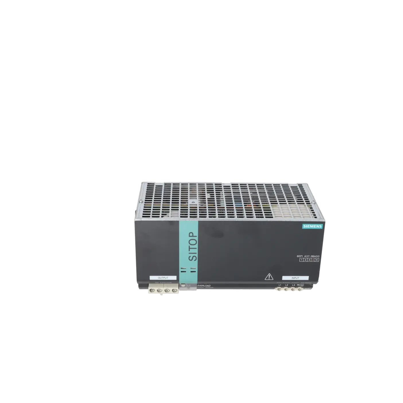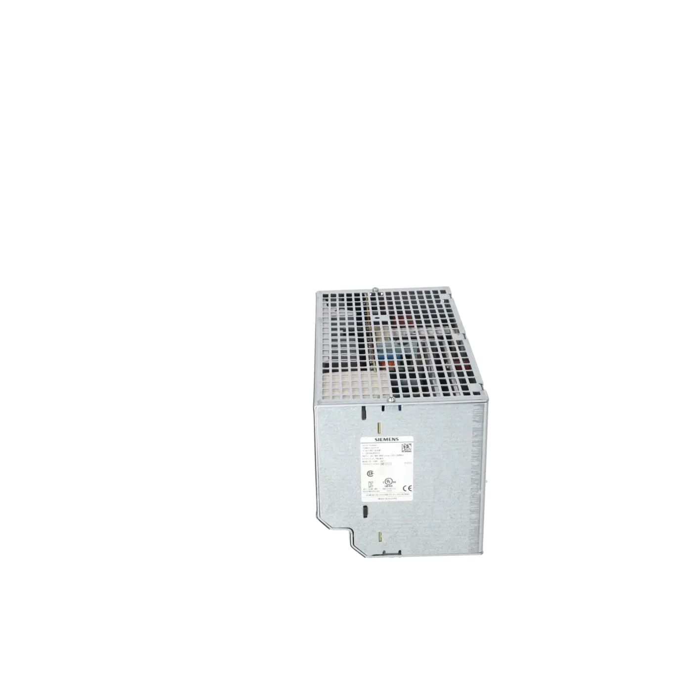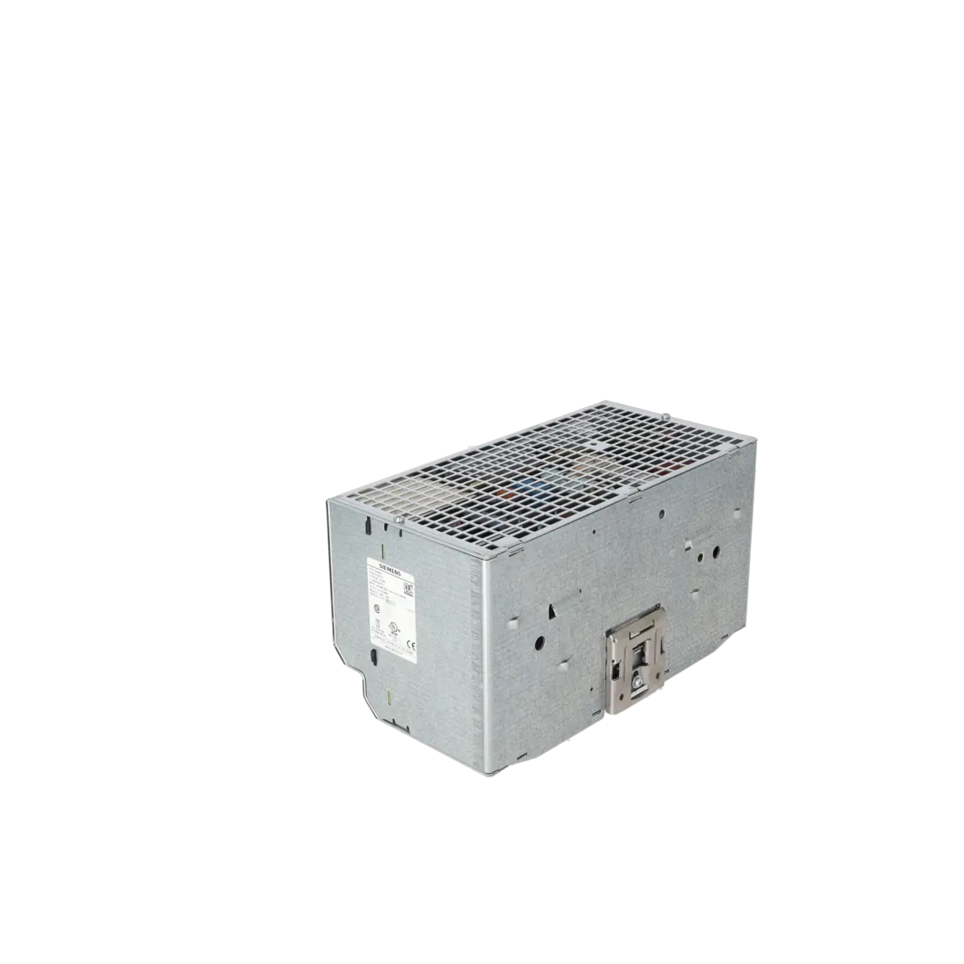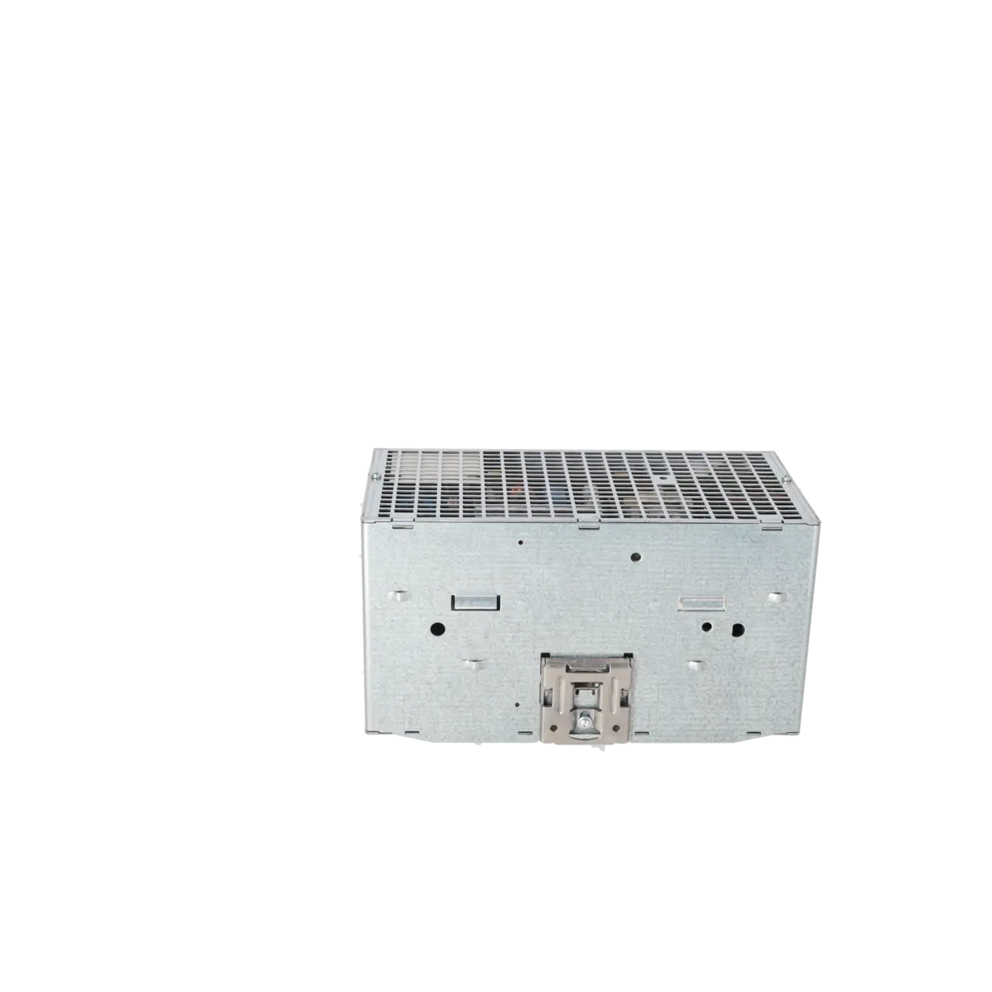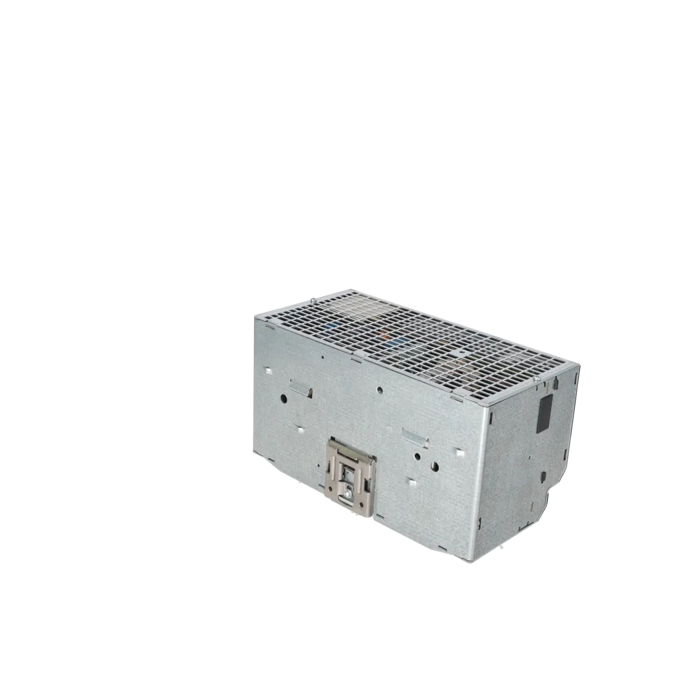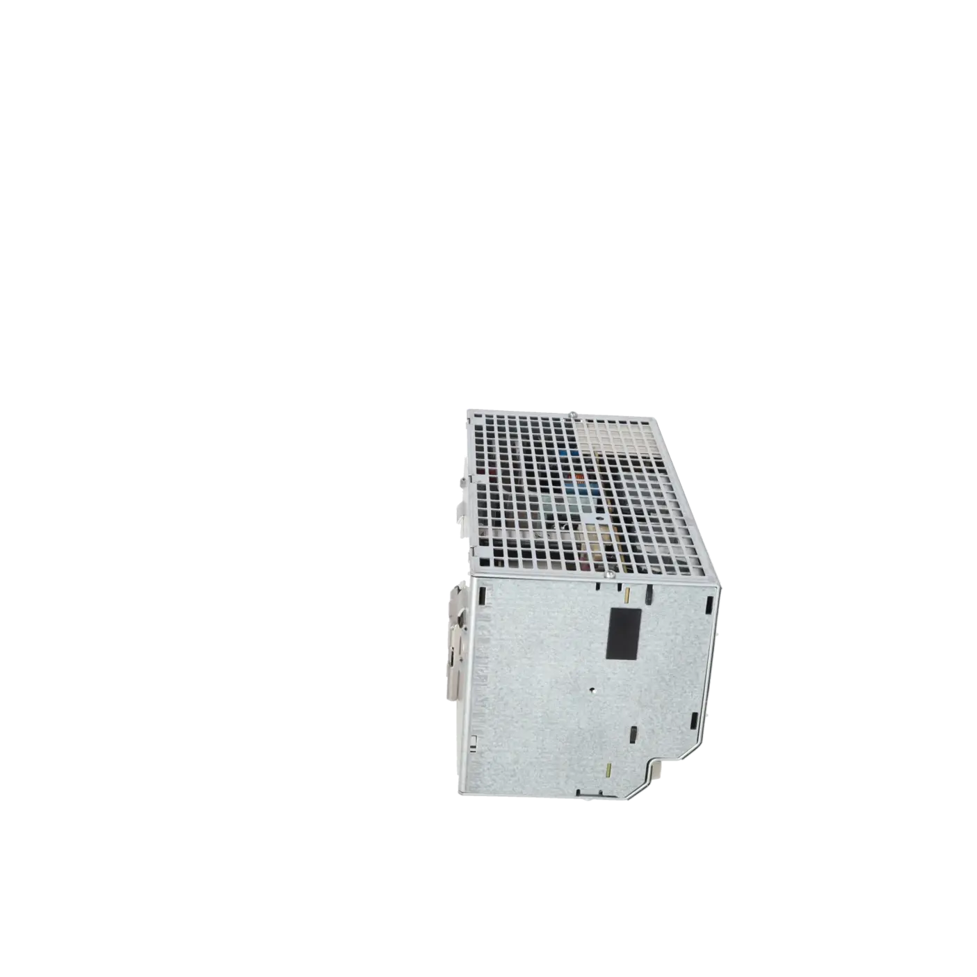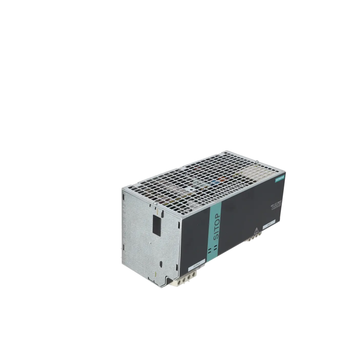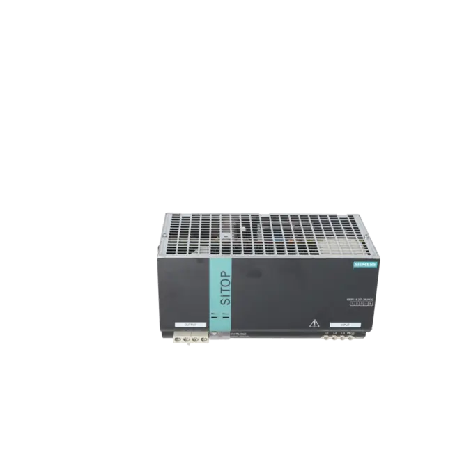
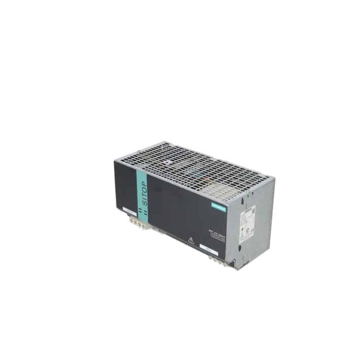
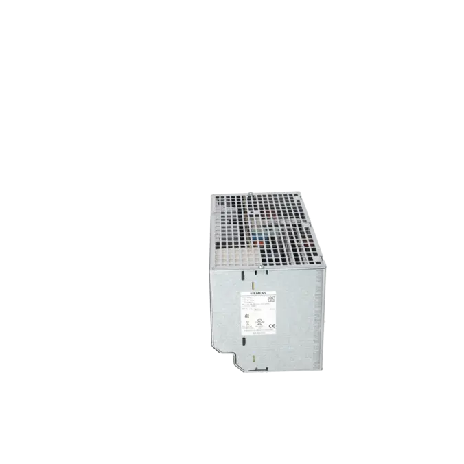
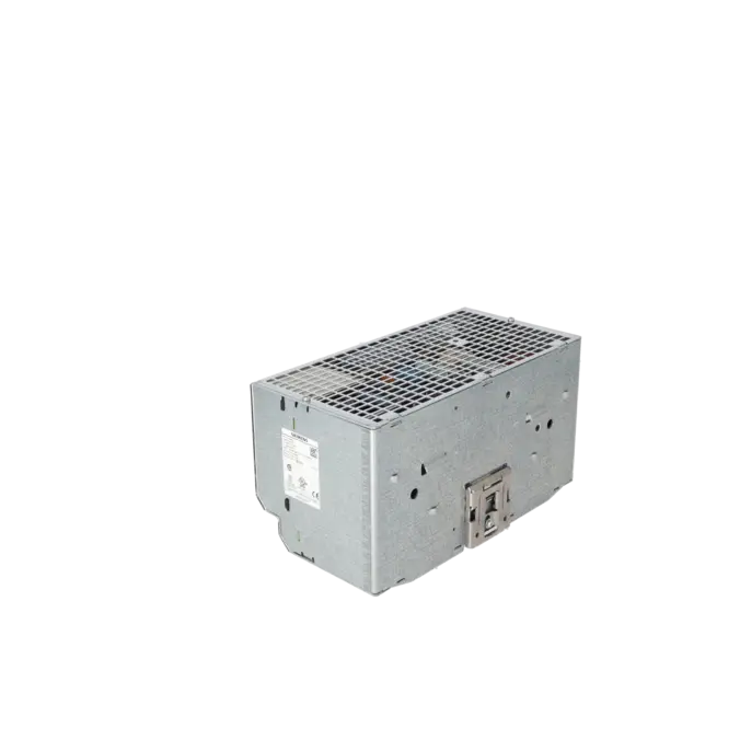
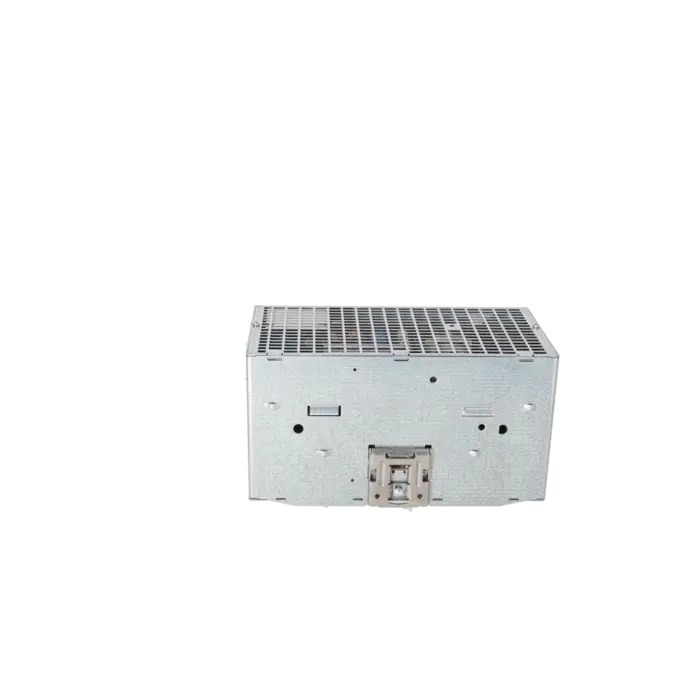
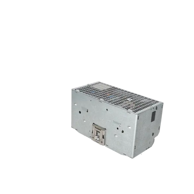
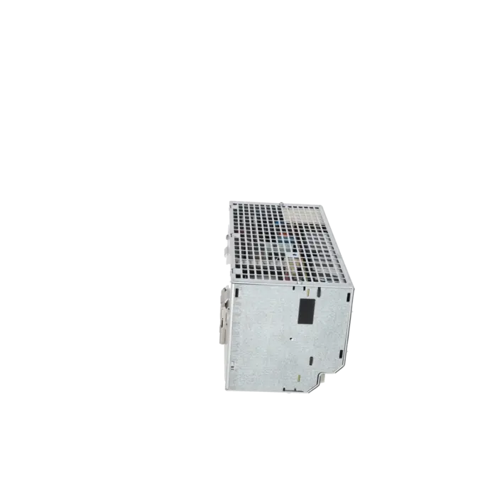
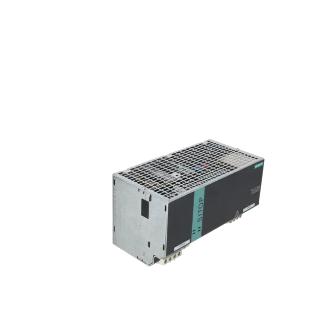
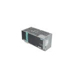
SIEMENS 6EP1437-3BA00
- EICHLER-art.no.: K0117317
- EAN: 4025515150619
- UPC: 754554810522
Product description
SITOP MODULAR 40 STABILIZED POWER SUPPLY INPUT: 400-500 V 3 AC OUTPUT: 24 V DC/40 A
Services for SIEMENS 6EP1437-3BA00
SIEMENS |
6EP1437-3BA00 –
additional product information
| Delivery information | |||
|---|---|---|---|
| Export identifier | AL: N ECCN: N | ||
| Net weight | 3.2 | ||
| Quantity | 1 Stück | ||
| Packaging quantity | 1 | ||
| Additional product information | |||
|---|---|---|---|
| Product status | |||
| EAN | 4025515150619 | ||
| UPC | 754554810522 | ||
| Static lot number | 85044083 | ||
| List indicator | KT10-PE | ||
| Product group | 4213 | ||
| Country of origin | RO | ||
| Compliance with the substance restrictions according to RoHS directive | Since: 20060801 | ||
| Product classifications | Version | Classification | |
|---|---|---|---|
| eClass | 4 | 27-04-07-02 | |
| eClass | 5.1 | 27-04-90-02 | |
| eClass | 6.0 | 27-04-90-02 | |
| ETIM | 3 | / | |
| ETIM | 4 | EC002540 | |
| ETIM | 5 | EC002540 | |
What is the 6EP1437-3BA00 and where is it used?
The 6EP1437-3BA00 is a three-phase SITOP modular power supply from Siemens for industrial 24 V DC networks with an output current of 40 A. The unit converts 3-phase AC 400–500 V into a regulated DC output voltage of 24 V, thereby providing up to 960 W for controllers, I/O modules, valve islands, sensors, IPCs, communication components and other 24 V loads. Thanks to its wide-range input, DIN-rail mounting and robust design, the module is particularly suitable for machines, control cabinets and production plants where a stable auxiliary voltage with high power reserve is required. For maintenance engineers, it is a key component because a failure often leads directly to plant downtime or knock-on faults in several sub-systems.
Overview of the key technical specifications and what they mean
The key specifications of the 6EP1437-3BA00 are directly relevant to system operation: The unit operates on 3-phase AC 400–500 V, starts at an input voltage (Ue) > 340 V, supplies 24 V DC / 40 A and allows voltage adjustment from 24 to 28.8 V via a potentiometer. This is useful for compensating for voltage drops over longer cables. The efficiency is around 90%, the residual ripple is a maximum of 100 mV, and the mains failure backup is at least 6 ms. In the event of a short circuit during operation, up to 120 A is available for 25 ms. Important for planning and troubleshooting: Derating of the output current applies from +60 to +70 °C, and derating is also required if the set output voltage exceeds 24 V.
Product status, life cycle status and obsolescence
Siemens has classified the 6EP1437-3BA00 as being in the Phase Out Announce life cycle stage. For operators of existing systems, this is a clear signal to secure their procurement and spare parts strategy at an early stage, as availability and predictability typically become more difficult over time. Siemens names 6EP3437-8SB00-0AY0 as the official successor, also a 3-phase 24 V/40 A power supply. This provides a verified migration path. When replacing existing units, however, it is important to compare not only the basic electrical function, but also installation space, wiring, accessories, lead times and project-specific approvals. Particularly in existing machinery, it is therefore often not just the successor model that is relevant, but also the guaranteed supply via repair, replacement or certified second-hand parts.
Available EICHLER services and when they are relevant in practice
For 6EP1437-3BA00, EICHLER offers several services, each of which is appropriate depending on the nature of the fault: repair, replacement, a used assembly, and a request for a new part. Repair is particularly relevant if the system is designed specifically for this assembly and the existing equipment is to be retained. It includes technical cleaning, preventive maintenance, comprehensive functional testing and a minimum 24-month warranty. In the event of acute breakdown, a replacement or an available used assembly is often the quickest way to minimise downtime. This is important for procurement and decision-makers because it allows for better safeguarding of the system’s functionality, spare parts supply and the risk of unplanned production breakdown, even as obsolescence progresses.
| Attribute | Value |
|---|---|
| input | |
| type of the power supply network | 3-phase AC |
| supply voltage at AC | |
| ● minimum rated value | 400 V |
| ● maximum rated value | 500 V |
| ● initial value | 320 V |
| ● full-scale value | 550 V |
| supply voltage at AC | Starting from Vin > 340 V |
| wide range input | Yes |
| overvoltage overload capability | 2.3 × Vin rated, 1.3 ms |
| buffering time for rated value of the output current in the event of power failure minimum | 6 ms |
| operating condition of the mains buffering | at Vin = 400 V |
| line frequency | 50/60 Hz |
| line frequency | 47 ... 63 Hz |
| input current | |
| ● at rated input voltage 400 V | 2.2 A |
| current limitation of inrush current at 25 °C maximum | 70 A |
| I2t value maximum | 2.8 A²·s |
| fuse protection type | none |
| fuse protection type in the feeder | Required: 3-pole connected miniature circuit breaker 10 ... 16 A characteristic C or circuit breaker 3RV2011-1DA10 (setting 3 A) or 3RV2711-1DD10 (UL 489) |
| output | |
| voltage curve at output | Controlled, isolated DC voltage |
| output voltage at DC rated value | 24 V |
| output voltage | |
| ● at output 1 at DC rated value | 24 V |
| output voltage adjustable | Yes; via potentiometer |
| adjustable output voltage | 24 ... 28.8 V; max. 960 W |
| relative overall tolerance of the voltage | 3 % |
| relative control precision of the output voltage | |
| ● on slow fluctuation of input voltage | 0.1 % |
| ● on slow fluctuation of ohm loading | 0.2 % |
| residual ripple | |
| ● maximum | 100 mV |
| voltage peak | |
| ● maximum | 200 mV |
| display version for normal operation | Green LED for 24 V OK |
| type of signal at output | via signaling module (6EP1961-3BA10) |
| behavior of the output voltage when switching on | No overshoot of Vout (soft start) |
| response delay maximum | 2.5 s |
| voltage increase time of the output voltage | |
| ● maximum | 500 ms |
| output current | |
| ● rated value | 40 A |
| ● rated range | 0 ... 40 A; +60 ... +70 °C: Derating 2%/K |
| supplied active power typical | 960 W |
| short-term overload current | |
| ● at short-circuit during operation typical | 120 A |
| duration of overloading capability for excess current | |
| ● at short-circuit during operation | 25 ms |
| constant overload current | |
| ● on short-circuiting during the start-up typical | 46 A |
| bridging of equipment | Yes; switchable characteristic |
| number of parallel-switched equipment resources for increasing the power | 2 |
| efficiency | |
| efficiency in percent | 90 % |
| power loss [W] | |
| ● at rated output voltage for rated value of the output current typical | 106 W |
| closed-loop control | |
| relative control precision of the output voltage with rapid fluctuation of the input voltage by +/- 15% typical | 1 % |
| relative control precision of the output voltage load step of resistive load 50/100/50 % typical | 2 % |
| setting time | |
| ● load step 50 to 100% typical | 4 ms |
| ● load step 100 to 50% typical | 4 ms |
| setting time | |
| ● maximum | 10 ms |
| protection and monitoring | |
| design of the overvoltage protection | < 35 V |
| property of the output short-circuit proof | Yes |
| design of short-circuit protection | Alternatively, constant current characteristic approx. 46 A or latching shutdown |
| ● typical | 46 A |
| enduring short circuit current RMS value | |
| ● typical | 46 A |
| display version for overload and short circuit | LED yellow for "overload", LED red for "latching shutdown" |
| safety | |
| galvanic isolation between input and output | Yes |
| galvanic isolation | Output voltage: SELV, ES1 (IEC 62368-1), DVC As (IEC 61204-7) |
| operating resource protection class | Class I |
| leakage current | |
| ● maximum | 3.5 mA |
| protection class IP | IP20 |
| EMC | |
| standard | |
| ● for emitted interference | EN 55022 Class B |
| ● for mains harmonics limitation | EN 61000-3-2 |
| ● for interference immunity | EN 61000-6-2 |
| standards, specifications, approvals | |
| certificate of suitability | |
| ● CE marking | Yes |
| ● UL approval | Yes; UL-Listed (UL 508), File E197259 |
| ● UKCA marking | Yes |
| ● EAC approval | Yes |
| ● Regulatory Compliance Mark (RCM) | Yes |
| ● NEC Class 2 | No |
| ● SEMI F47 | Yes |
| type of certification | |
| ● CB-certificate | No |
| MTBF at 40 °C | 485 437 h |
| standards, specifications, approvals hazardous environments | |
| certificate of suitability | |
| ● IECEx | No |
| ● ATEX | No |
| ● ULhazloc approval | No |
| ● FM registration | No |
| standards, specifications, approvals marine classification | |
| shipbuilding approval | No |
| Marine classification association | |
| ● American Bureau of Shipping Europe Ltd. (ABS) | No |
| ● French marine classification society (BV) | No |
| ● Det Norske Veritas (DNV) | No |
| ● Lloyds Register of Shipping (LRS) | No |
| standards, specifications, approvals Environmental Product Declaration | |
| Environmental Product Declaration | Yes |
| global warming potential [CO2 eq] | |
| ● total | 2 762.3 kg |
| ● during manufacturing | 76.5 kg |
| ● during operation | 2 684.2 kg |
| ● after end of life | 0.64 kg |
| ambient conditions | |
| ambient temperature | |
| ● during operation | 0 ... 70 °C; with natural convection |
| ● during transport | -40 ... +85 °C |
| ● during storage | -40 ... +85 °C |
| environmental category according to IEC 60721 | Climate class 3K3, 5 ... 95% no condensation |
| connection method | |
| type of electrical connection | screw terminal |
| ● at input | L1, L2, L3, PE: 1 screw terminal each for 0.2 ... 4 mm² single-core/finely stranded |
| ● at output | +, -: 2 screw terminals each for 0.33 ... 10 mm² |
| ● for auxiliary contacts | - |
| mechanical data | |
| width × height × depth of the enclosure | 240 × 125 × 125 mm |
| installation width × mounting height | 240 mm × 225 mm |
| required spacing | |
| ● top | 50 mm |
| ● bottom | 50 mm |
| ● left | 0 mm |
| ● right | 0 mm |
| fastening method | Snaps onto DIN rail EN 60715 35x15 |
| ● DIN-rail mounting | Yes |
| ● S7 rail mounting | No |
| ● wall mounting | No |
| housing can be lined up | Yes |
| net weight | 3.2 kg |
| Fault description | Possible solution |
|---|---|
| Why does the yellow LED light up and the 24 V voltage drop on the 6EP1437-3BA00? | The yellow LED indicates an overload in constant-current operating mode. The power supply then limits the output current and reduces the output voltage. Check the 24 V load for short circuits, excessive inrush currents, faulty loads and undersized cables. Disconnect the loads one by one and first measure the output voltage at no load. If the yellow LED remains lit even with the load disconnected, an internal fault is likely and repair or replacement is usually the more cost-effective option. |
| Why is the red LED lit on the 6EP1437-3BA00 and why does the device not restart automatically? | The red LED indicates a memory-based shutdown. This operating mode is controlled by switch B. If an overload persists for longer than 100 ms, the device shuts down and remains in this state until the mains supply is switched off for at least 5 seconds. You should therefore first rectify the cause of the fault on the 24 V side, then check the position of switch B and finally reset the power supply correctly. If a signalling module is also in use, a red light may also indicate a remote shutdown. |
| Why is there no 24 V output voltage and the LED is not lit, even though power is being supplied? | According to Siemens, if no LED is lit, this indicates a lack of supply voltage. Check that all three phases (L1, L2, L3) and the earth (PE) are correctly connected, that the mains voltage is within the permissible range, and that the start-up voltage of over 340 V is being reached. Also check the upstream fuse, terminal connections and for a possible phase failure. Particularly with 3-phase power supplies, a wiring or fuse fault can quickly cause the device to appear "dead" from the outside, even though the fault lies not at the output but on the AC side. |
| Why does the 24 V voltage drop under load, even though there is no obvious short circuit? | Common causes include overloading close to or above 40 A, excessive ambient temperature, or an incorrect switch setting. From +60 °C, the output current must be reduced. If the output voltage is increased above 24 V, derating is also required. In addition, switch A alters the characteristic curve in parallel operation: the output voltage then drops as the current increases. If a device is accidentally set to parallel operation although it is being operated individually, this may appear to be a voltage fault. You should therefore check the load profile, temperature, setpoint voltage and switch position together. |
| Why does the supply fuse of the 6EP1437-3BA00 trip on switch-on? | The device has an inrush current of up to 70 A. Siemens therefore requires a suitable protective circuit in the mains supply line, for example a 3-pole coupled circuit breaker 10–16 A with characteristic C or the circuit breakers mentioned. If the supply trips as soon as the unit starts up, the protective device, tripping characteristic and wiring should be checked against the manufacturer’s specifications. Ageing or incorrectly rated supply circuits can also lead to recurring start-up problems in this context. |
Is 6EP1437-3BA00 still available or has it already been discontinued?
Siemens lists 6EP1437-3BA00 as being in the Phase Out Announce status. For operators, this does not automatically mean that all procurement options cease immediately, but the product lifecycle has clearly shifted towards the end-of-life phase. It therefore makes sense for procurement and maintenance departments to secure spare parts requirements, inventory strategy and potential service options at an early stage. Particularly with centralised 24 V power supplies, an unplanned failure is often critical, as several system components may be affected simultaneously.
What is the successor model specified by Siemens for the 6EP1437-3BA00?
Siemens specifies the 6EP3437-8SB00-0AY0 as the official successor. This successor belongs to the SITOP PSU8200 series and covers the same basic electrical class, with a 3-phase 400–500 V AC input and a 24 V DC / 40 A output. This is the obvious choice for a modernisation. However, before proceeding with a 1:1 replacement, installation dimensions, wiring, accessories, holding time and project-specific approvals should be checked to ensure that a formally suitable successor also results in a technically sound retrofit.
Can I connect two 6EP1437-3BA00 units in parallel?
Yes, the unit is designed for parallel connection. Siemens refers to a switchable characteristic curve and specifies two units connected in parallel to achieve the power increase. The correct switch setting is crucial here: Switch A activates the characteristic curve for parallel operation. In this setting, the output voltage decreases as the current increases, ensuring that the load is distributed more evenly. This operating mode should not be accidentally active during single operation, as it alters the voltage behaviour under load.
What protection is required for the 6EP1437-3BA00 power supply?
Siemens requires a suitable protective circuit in the mains supply line. They specify a 3-pole interlocked circuit breaker rated at 10–16 A, characteristic C, or, alternatively, certain circuit breakers. This requirement is important because the power supply unit can have a high inrush current. Anyone experiencing issues with tripping fuses during commissioning or after replacing a module should therefore not only check the power supply unit itself, but also compare the upstream protection technology and its characteristic curve with the manufacturer’s specifications.
Can the output voltage of the 6EP1437-3BA00 be adjusted?
Yes, the output voltage can be adjusted via a potentiometer from 24 to 28.8 V. This is useful if line losses to the load need to be compensated for. However, the consequence is important: if the voltage is raised above 24 V, Siemens requires derating. This is to prevent thermal overload. In practice, therefore, the voltage should only be increased as far as is strictly necessary to supply the furthest-away load.
For which environment and mounting is the 6EP1437-3BA00 designed?
The power supply unit is designed for DIN rail mounting in accordance with EN 60715, has an IP20 protection rating and is designed for operation at temperatures between 0 and 70 °C. For installation, Siemens specifies mounting clearances of 50 mm at the top and bottom. Mechanically, measuring 240 × 125 × 125 mm, the unit is a rather powerful control cabinet power supply that requires sufficient space and thermal headroom during planning. These specifications are particularly important when a module in a densely populated control cabinet is to be replaced or converted to a successor model.