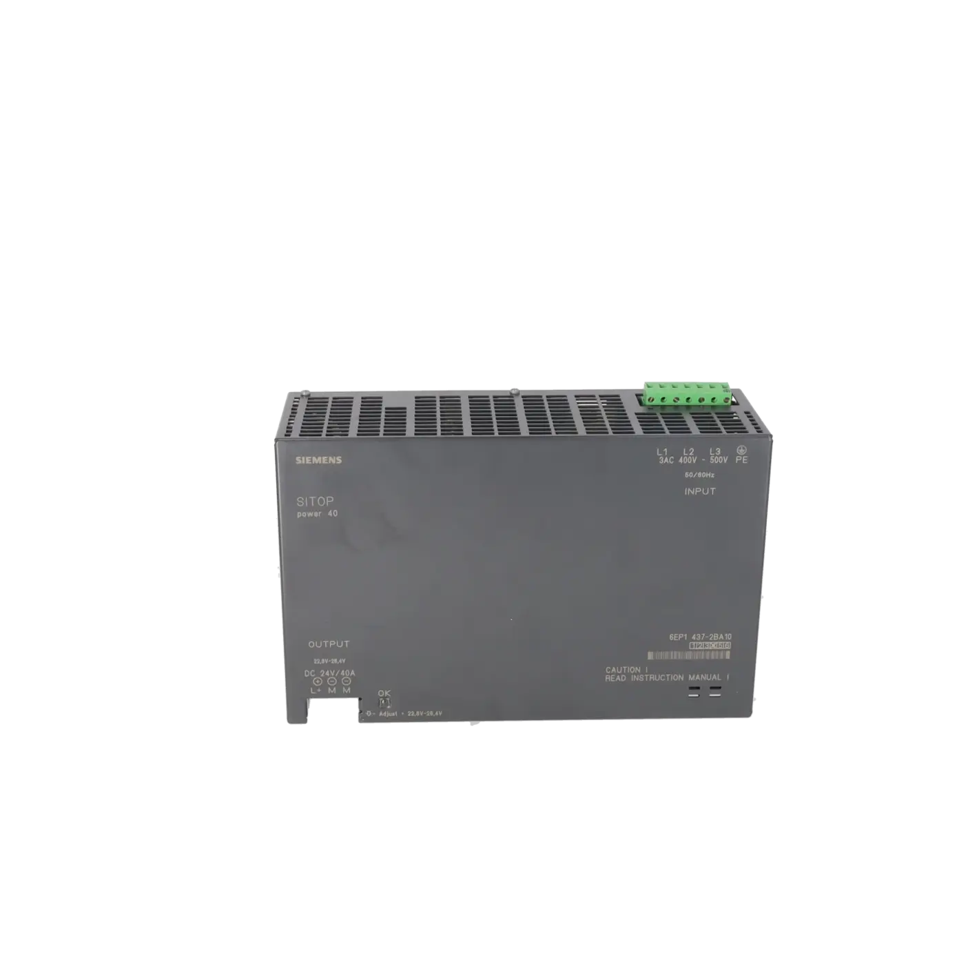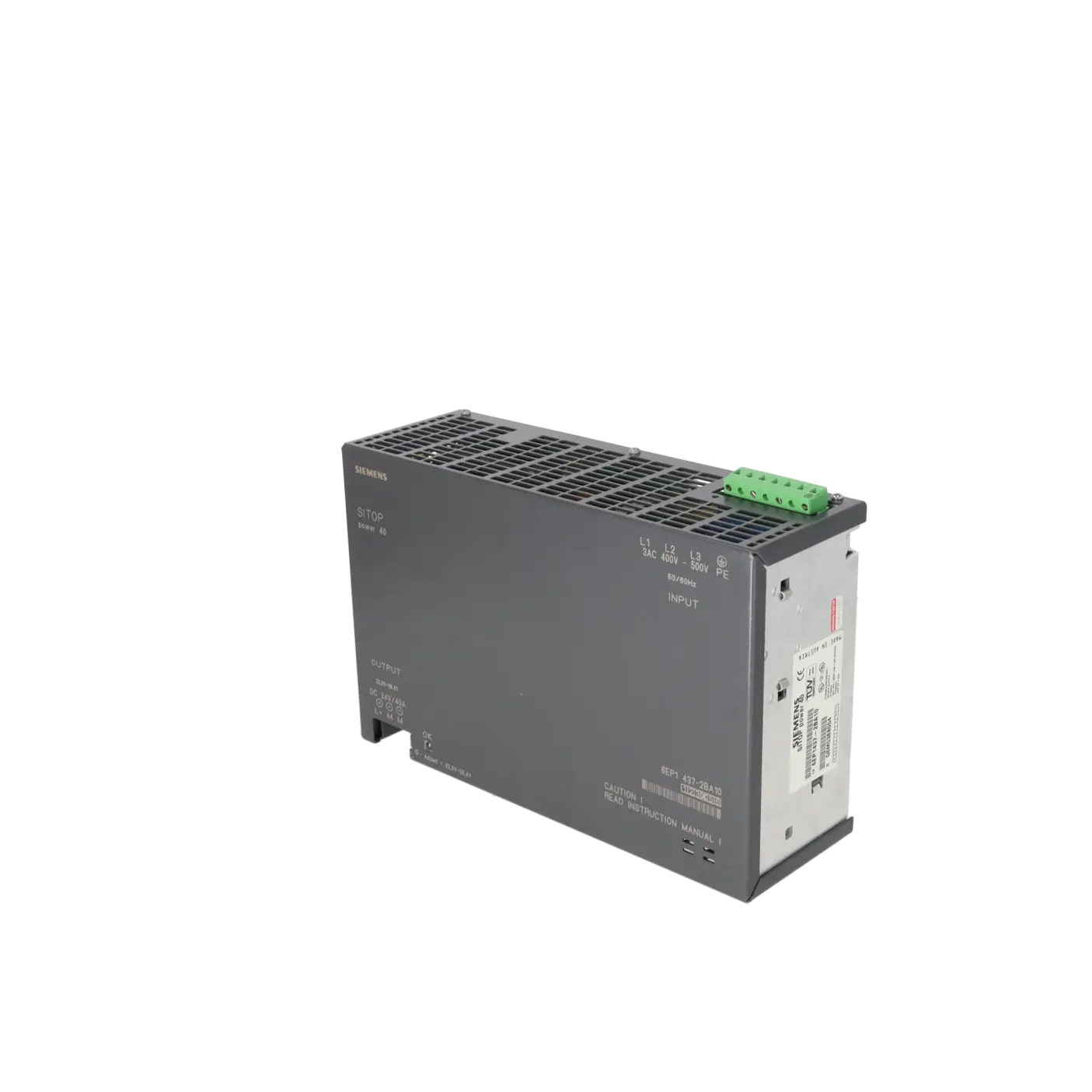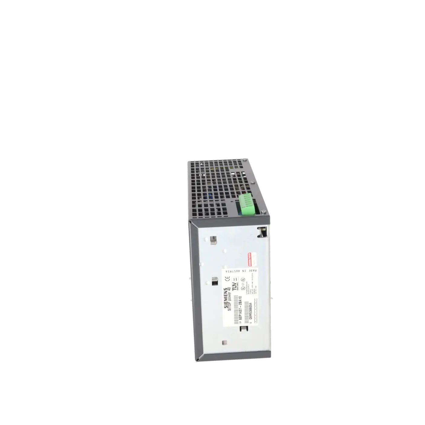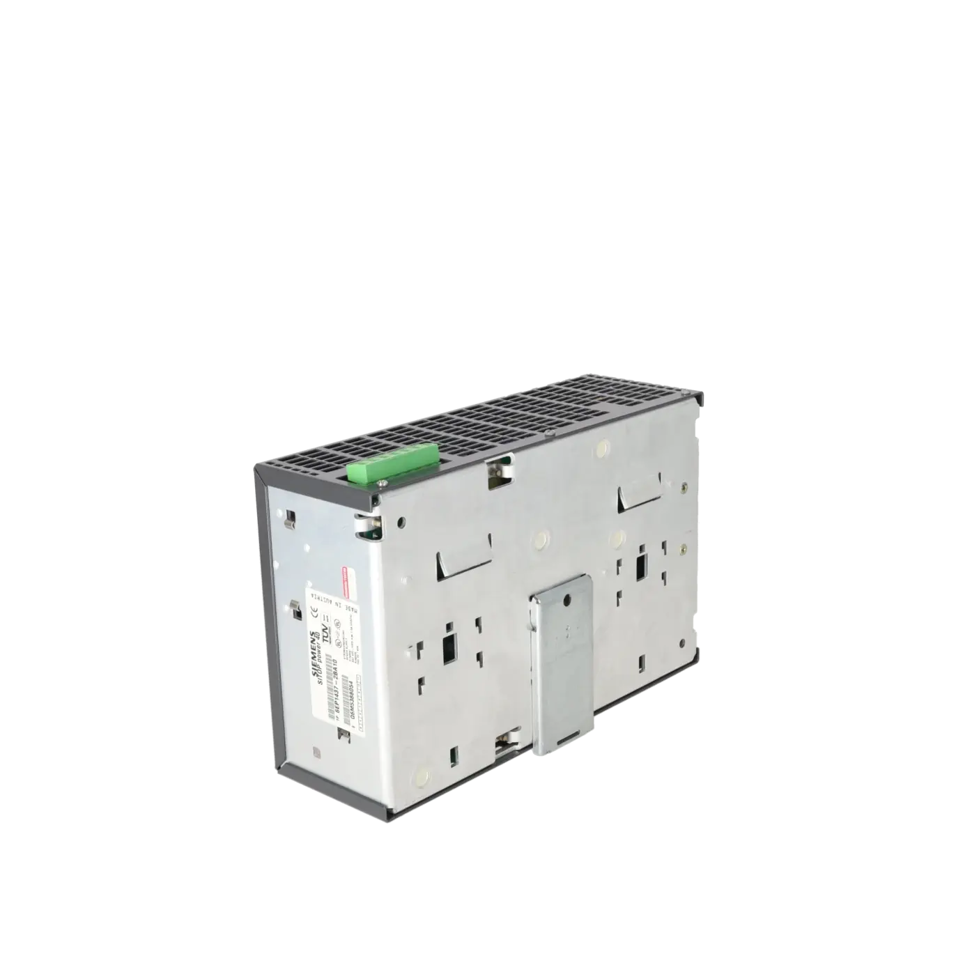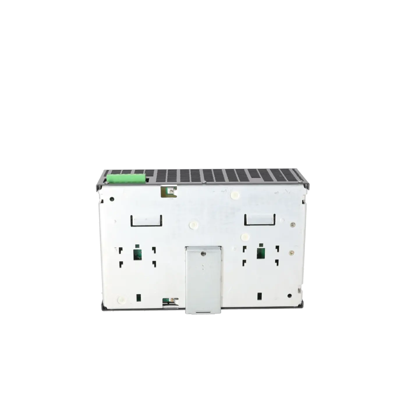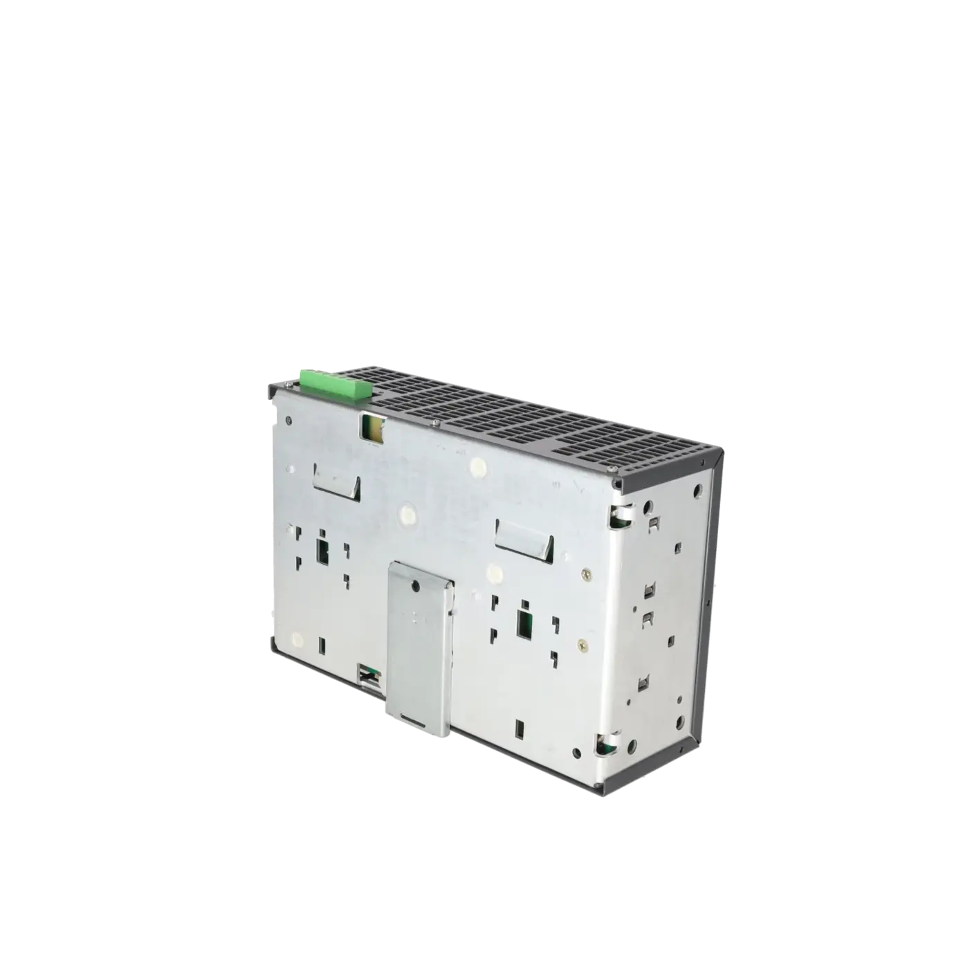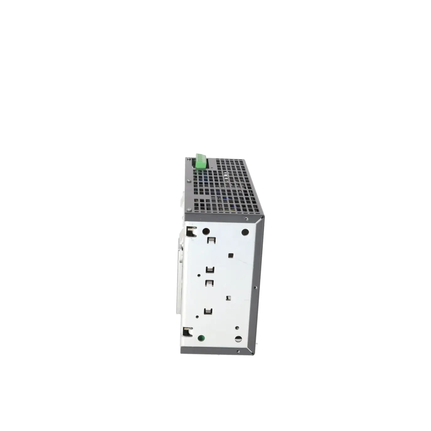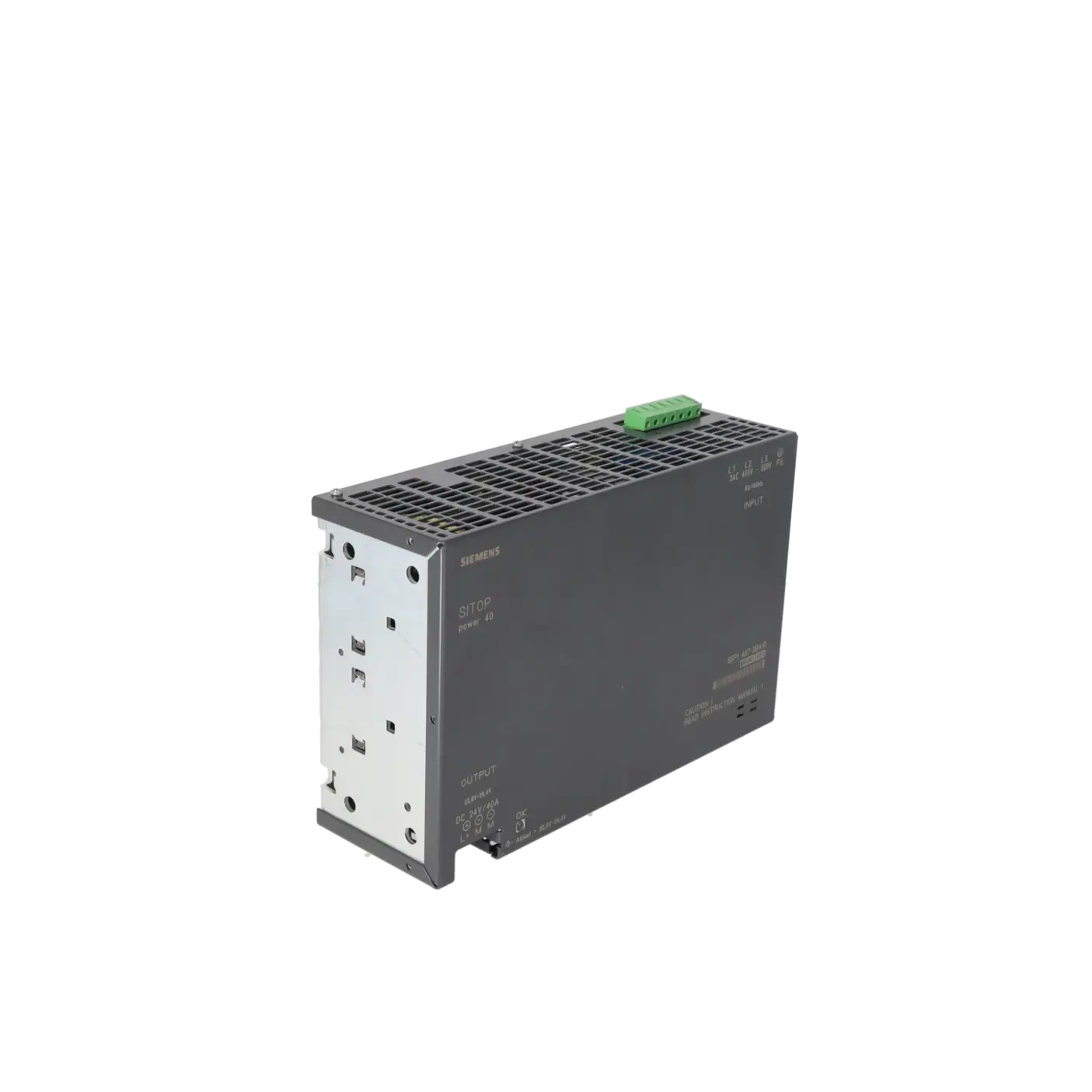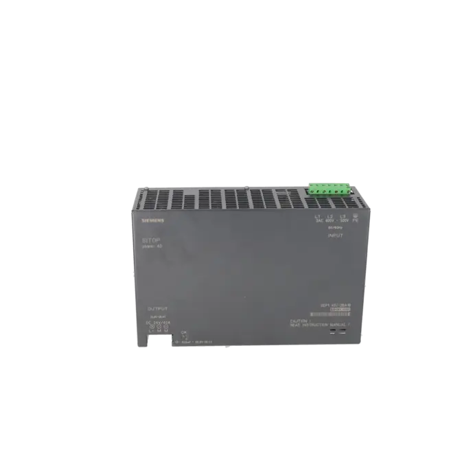
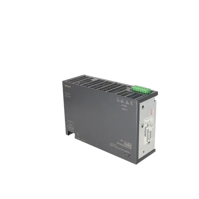
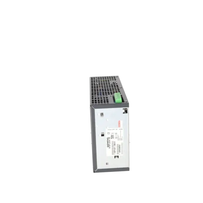
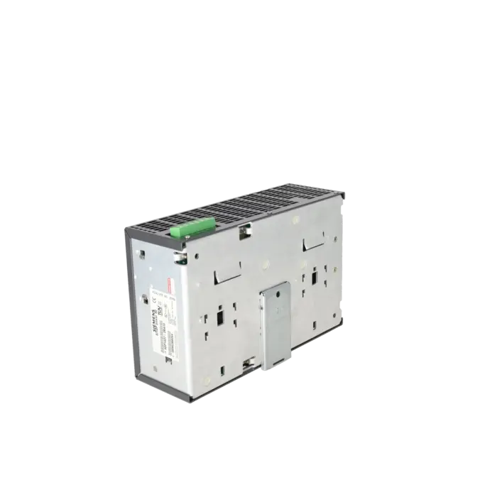
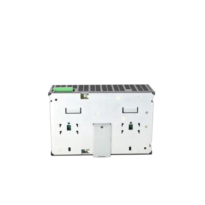
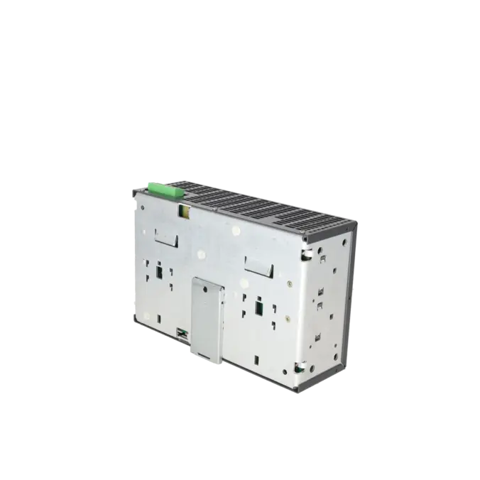
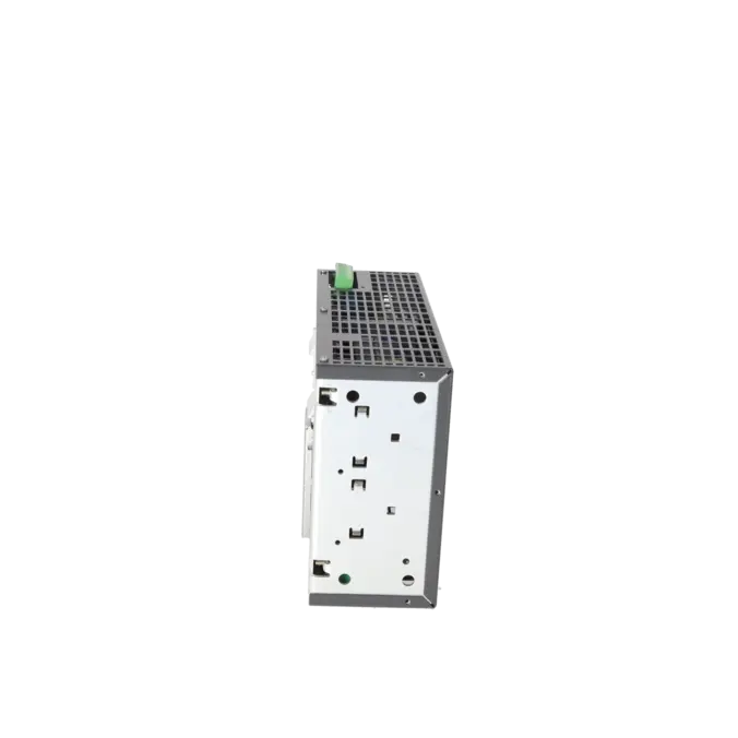
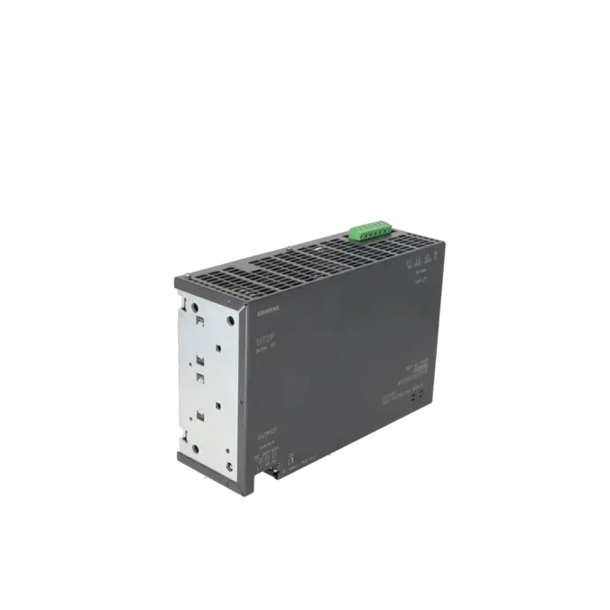
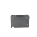
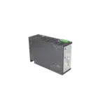
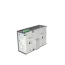
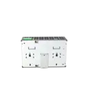
SIEMENS 6EP1437-2BA10
- EICHLER-art.no.: K0117316
- EAN: 4025515150268
Product description
SITOP POWER 40 GEREGELTE LASTSTROMVERSORGUNG EINGANG: 3 X AC 400 - 500 V AUSGANG: DC 24 V/40A
Services for SIEMENS 6EP1437-2BA10
SIEMENS |
6EP1437-2BA10 –
additional product information
| Delivery information | |||
|---|---|---|---|
| Export identifier | AL: ECCN: | ||
| Net weight | 3.8 | ||
| Quantity | 1 Stück | ||
| Packaging quantity | 1 | ||
| Additional product information | |||
|---|---|---|---|
| Product status | EOP: 2001-05-31 | ||
| EAN | 4025515150268 | ||
| UPC | / | ||
| Static lot number | 85044090 | ||
| List indicator | / | ||
| Product group | 4741 | ||
| Country of origin | RO | ||
| Compliance with the substance restrictions according to RoHS directive | Since: / | ||
| Product classifications | Version | Classification | |
|---|---|---|---|
| eClass | 4 | / | |
| eClass | 5.1 | / | |
| eClass | 6.0 | / | |
| ETIM | 3 | / | |
| ETIM | 4 | / | |
| ETIM | 5 | / | |
What is the 6EP1437-2BA10 and where is it used?
The SIEMENS 6EP1437-2BA10 is a regulated SITOP POWER 40 power supply designed for industrial 24 V DC power-distribution systems. The unit operates from a three-phase AC input of 400 to 500 V and provides a 24 V DC output at 40 A. This makes the assembly suitable for high-power control and supply circuits in machinery and industrial systems, wherever PLCs, I/O systems, valve islands, sensors, actuators or auxiliary circuits must be supplied reliably from a central 24 V DC bus. For maintenance engineers, the article number is particularly important because it refers to an older 40 A design that is still widely used in legacy installations and is therefore frequently required as a spare part, replacement unit or repair candidate.
Overview of the key technical data and what it means
For a quick technical assessment, the most relevant specifications are as follows: three-phase AC input, nominal voltage of 400 to 500 V, input range of 360 to 550 V, 24 V DC output, nominal output current of 40 A and a typical output power of 960 W. The output voltage can be adjusted between 22.8 and 26.4 V, which helps compensate for voltage drops in longer 24 V DC cable runs. Other important diagnostic and operating features include the green 24 V O.K. status indicator, current limiting between 42 and 52 A, electronic short-circuit protection with automatic restart, IP20 protection, an operating temperature range of 0 to 55 °C and physical dimensions of 280 × 180 × 92 mm with a weight of approximately 3.6 kg.
Product status, life-cycle status and obsolescence
For the 6EP1437-2BA10, the product information lists an EOSR (End of Support and Repair) date of 30 September 2014. For purchasing and engineering teams, this is a clear indication that the product is in an advanced stage of its life cycle and therefore carries an increased obsolescence risk. This is precisely why reliable repair services, replacement options and secure procurement channels are so important in existing installations. Siemens later introduced a new 40 A PSU300S power supply to replace the older 6EP1437-2BA00 and 6EP1437-2BA10 models. In Siemens support documentation, this successor is identified as 6EP1437-2BA20. Before replacing the original unit, however, the mechanical dimensions, wiring arrangement and installation conditions of the existing system should always be checked to ensure compatibility with the successor model.
Available EICHLER services and when they are relevant in practice
For this model, EICHLER offers several options: repair, replacement, used parts and new parts on request. Repair is particularly attractive when the system should continue operating without any mechanical or electrical modifications and when migration to a newer generation of power supplies is to be avoided. EICHLER’s repair service includes technical cleaning, preventive maintenance, comprehensive functional testing and a minimum 24-month warranty. Replacement is generally the preferred option when the cost of a breakdown is high and power must be restored as quickly as possible. Used parts are often attractive when procurement speed and budget are the primary concerns. For decision-makers, this combination of services is particularly valuable because it helps maintain the operational reliability of older installations even when the product has reached an advanced stage of its life cycle.
| Attribute | Value |
|---|---|
| Input | |
| Input | 3-phase AC |
| Rated voltage value Vin rated | 400 ... 500 V |
| Voltage range AC | 360 ... 550 V |
| ● Note | 340 ... 360 V for max. 2 s or at max. 0.9 x Iout rated |
| Wide-range input | Yes |
| Overvoltage resistance | 2.3 × Vin rated, 1.3 ms |
| Mains buffering at Iout rated, min. | 3 ms; at Vin = 360 V |
| Rated line frequency 1 | 50 Hz |
| Rated line frequency 2 | 60 Hz |
| Rated line range | 47 ... 63 Hz |
| Input current | |
| ● at rated input voltage 400 V | 1.9 A |
| Switch-on current limiting (+25 °C), max. | 25 A |
| I²t, max. | 1 A²·s |
| Built-in incoming fuse | none |
| Protection in the mains power input (IEC 898) | Required: 3-pole connected miniature circuit breaker characteristic C up to 25 A (recommended: 6 A) or circuit-breaker 3RV1021-1DA10 (setting 3 A) or 3RV1721-1DD10 (UL 489) |
| Output | |
| Output | Controlled, isolated DC voltage |
| Rated voltage Vout DC | 24 V |
| Total tolerance, static ± | 3 % |
| Residual ripple peak-peak, max. | 150 mV |
| Residual ripple peak-peak, typ. | 50 mV |
| Spikes peak-peak, max. (bandwidth: 20 MHz) | 240 mV |
| Spikes peak-peak, typ. (bandwidth: 20 MHz) | 200 mV |
| Adjustment range | 22.8 ... 26.4 V |
| Product function Output voltage adjustable | Yes |
| Output voltage setting | via potentiometer; only permissible at ambient temperatur 0 °C to +45 °C |
| Status display | Green LED for 24 V OK |
| On/off behavior | Slight overshoot of Vout (< 2 V for max. 500 ms) |
| Startup delay, max. | 3 s |
| Voltage rise, typ. | 40 ms |
| Rated current value Iout rated | 40 A |
| Current range | 0 ... 40 A |
| Supplied active power typical | 960 W |
| Short-term overload current | |
| ● on short-circuiting during the start-up typical | 70 A |
| ● at short-circuit during operation typical | 70 A |
| Duration of overloading capability for excess current | |
| ● on short-circuiting during the start-up | 600 ms |
| ● at short-circuit during operation | 600 ms |
| Parallel switching for enhanced performance | Yes; only permissable at ambient temperature 0 °C to 45 °C |
| Numbers of parallel switchable units for enhanced performance | 2 |
| Efficiency | |
| Efficiency at Vout rated, Iout rated, approx. | 90 % |
| Power loss at Vout rated, Iout rated, approx. | 107 W |
| Closed-loop control | |
| Dynamic mains compensation (Vin rated ±15 %), max. | 1 % |
| Dynamic load smoothing (Iout: 50/100/50 %), Uout ± typ. | 4 % |
| Setting time maximum | 3 ms |
| Protection and monitoring | |
| Output overvoltage protection | Yes, according to EN 60950 |
| Current limitation | 42 ... 52 A |
| Property of the output Short-circuit proof | Yes |
| Short-circuit protection | Electronic shutdown, automatic restart |
| Enduring short circuit current RMS value | |
| ● maximum | 62 A |
| Overload/short-circuit indicator | - |
| Safety | |
| Primary/secondary isolation | Yes |
| Galvanic isolation | Safety extra low output voltage Vout according to EN 60950-1 |
| Protection class | Class I |
| Leakage current | |
| ● maximum | 3.5 mA |
| ● typical | 0.78 mA |
| CE mark | Yes |
| UL/cUL (CSA) approval | cULus-Listed (UL 508, CSA C22.2 No. 142), File E143289 |
| Explosion protection | - |
| FM approval | - |
| CB approval | Yes |
| Marine approval | - |
| Degree of protection (EN 60529) | IP20 |
| EMC | |
| Emitted interference | EN 55022 Class B |
| Supply harmonics limitation | EN 61000-3-2 |
| Noise immunity | EN 61000-6-2 |
| Operating data | |
| Ambient temperature | |
| ● during operation | 0 ... 55 °C |
| — Note | with natural convection |
| ● during transport | -25 ... +85 °C |
| ● during storage | -25 ... +85 °C |
| Humidity class according to EN 60721 | Climate class 3K3, no condensation |
| Mechanics | |
| Connection technology | screw-type terminals |
| Connections | |
| ● Supply input | L1, L2, L3, PE: 1 screw terminal each for 0.5 ... 2.5 mm² single-core/finely stranded |
| ● Output | L+: 1 screw terminal for 0.33 ... 10 mm²; M: 2 screw terminals for 0.33 ... 10 mm² |
| ● Auxiliary | - |
| Width of the enclosure | 280 mm |
| Height of the enclosure | 180 mm |
| Depth of the enclosure | 92 mm |
| Required spacing | |
| ● top | 50 mm |
| ● bottom | 50 mm |
| ● left | 40 mm |
| ● right | 0 mm |
| Weight, approx. | 3.6 kg |
| Product feature of the enclosure housing for side-by-side mounting | No |
| Installation | Snaps onto DIN rail EN 60715 35x15 |
| Mechanical accessories | Mounting bracket 90° (6EP1971-2BA00) |
| MTBF at 40 °C | 515 274 h |
| Other information | Specifications at rated input voltage and ambient temperature +25 °C (unless otherwise specified) |
| Fault Description | Possible Solution |
|---|---|
| Why is the 6EP1437-2BA10 no longer supplying 24 V and the operating indicator remains off? | First, verify that the three-phase supply voltage is present and that the specified upstream protection devices are installed. If the O.K. indicator remains off, possible causes include a missing input supply, overload operation with current limiting or hiccup mode, or thermal shutdown. Disconnect the 24 V load for testing purposes, measure the input voltage on L1, L2 and L3, and check the upstream circuit protection before concluding that the power supply itself is defective. |
| Why does the 24 V output voltage collapse under load or pulse repeatedly? | The 6EP1437-2BA10 limits its output current to approximately 42–52 A. In the event of a short circuit or severe overload, the unit performs an electronic shutdown followed by automatic restart. Therefore, disconnect individual 24 V circuits one at a time and check for short circuits, defective loads, seized solenoid valves or excessive inrush currents. The output voltage will only stabilise permanently once the connected load has been reduced to within the permissible operating range. |
| Why does the power supply switch off after operating for some time? | The cause is often thermal. For the 6EP1437-2BA10, Siemens specifies an operating temperature range of 0 to 55 °C, natural convection cooling and minimum installation clearances of 50 mm above and below, 40 mm on the left-hand side and 0 mm on the right-hand side. In addition, output-voltage adjustment is only permitted within the temperature range of 0 to 45 °C. Check the temperature inside the control cabinet, inspect ventilation paths for contamination, verify that the continuous load is not excessive and confirm whether the output voltage has been adjusted above the nominal setting. Insufficient clearance or excessive ambient temperature significantly increases the likelihood of thermal shutdown. |
| Why does the upstream fuse or circuit breaker trip during power-up? | The device requires a three-pole linked protective device with a type-C tripping characteristic in the mains supply. Siemens specifies ratings of up to 25 A and recommends 6 A, or alternatively a suitable circuit breaker. Therefore, not only the current rating but also the correct tripping characteristic and three-pole coupling are important. Check the protective device, the condition of the supply wiring and the input wiring configuration, as an unsuitable protection device can repeatedly trip during start-up. |
| Why does the parallel operation of two power supplies not function correctly, or why is the load shared unevenly? | The 6EP1437-2BA10 can be connected in parallel to increase output power, but only with two units and only within the specified operating temperature range. Siemens notes for PSU300S parallel operation that identical power-supply types should be used and that the no-load output voltages must be carefully matched. The voltage difference between the units should not exceed 50 mV. Therefore, verify that the units are identical, check cable lengths and common connection points, and perform accurate voltage matching before connecting the load. |
Is the 6EP1437-2BA10 discontinued or still available?
The product is clearly in an advanced stage of its life cycle, as the product data indicates an EOSR date of 30 September 2014. At the same time, the unit remains highly relevant for procurement because EICHLER continues to offer repair, exchange, used parts and new parts on request. For purchasing and production departments, the key question today is therefore not whether the unit still exists somewhere, but which procurement route offers the lowest risk of breakdown and the shortest recovery time.
What is the Siemens successor to the 6EP1437-2BA10?
Siemens introduced a new 40 A PSU300S power supply to replace the older 6EP1437-2BA00 and 6EP1437-2BA10 models. In Siemens support documentation, the 40 A version is listed as 6EP1437-2BA20. However, replacement decisions in existing systems should not be based solely on voltage and current ratings. Installation dimensions, terminal locations, wiring arrangements and available panel space should all be checked in advance to ensure that an electrical successor does not turn into a mechanical modification project.
Which specifications are most important for quick identification during procurement?
In most cases, five key specifications are sufficient for reliable identification: a three-phase AC input, a rated input voltage of 400 to 500 V, a 24 V DC output, a rated output current of 40 A and the exact part number 6EP1437-2BA10. Additional useful details include EAN 4025515150268, a weight of approximately 3.6 to 3.8 kg and dimensions of 280 × 180 × 92 mm. These details help prevent confusion with other SITOP 40 A or PSU300S variants and significantly speed up enquiries to purchasing departments, stores personnel or service providers.
What protection and power supply requirements does the 6EP1437-2BA10 have?
The power supply is designed for a three-phase AC input of 400 to 500 V and accepts an input range of 360 to 550 V. A three-pole linked protective device with a type-C tripping characteristic is specified for the incoming supply. Siemens states ratings of up to 25 A and recommends 6 A, alternatively using suitable circuit breakers. In practice, this is important because incorrectly selected protective devices can cause nuisance tripping or make fault diagnosis more difficult. For proper system design, the incoming supply, protective devices and existing control cabinet documentation should therefore always be reviewed together.
Can I increase the output voltage to compensate for voltage drop in the wiring?
Yes. The output voltage of the 6EP1437-2BA10 can be adjusted between 22.8 and 26.4 V. This is particularly useful when long 24 V cable runs or remotely located loads experience excessive voltage drop. However, according to the product specifications, output-voltage adjustment is only permitted within an ambient temperature range of 0 to 45 °C. Before increasing the voltage setting, the actual voltage drop, available load reserve and cabinet temperature should be measured to avoid creating additional thermal stress within the system.
Can I connect two units in parallel to increase available power?
Yes. Two identical units may be connected in parallel to increase available output power. To ensure proper load sharing, identical power supplies must be used and their no-load output voltages must be matched very accurately. Siemens specifies a maximum voltage difference of 50 mV. For maintenance personnel, this can be an effective solution when existing 24 V loads have been expanded. However, decision-makers should remember that parallel operation increases available power capacity but does not replace a properly designed redundancy, selectivity and load-distribution strategy within the 24 V system.
How can I identify a developing fault at an early stage?
One of the most common early warning signs is intermittent voltage dips on the 24 V supply rail, even though the system does not suffer a complete breakdown. Monitoring the 24 V O.K. indicator and recording the 24 V supply using Min/Max measurements or trend logging can help detect such issues. In one PLC forum case involving a faulty SITOP power supply, the output voltage appeared normal at 24.2 V most of the time but occasionally dropped briefly to 12.3 V. Short-duration voltage dips of this kind can cause CPU, HMI or fieldbus faults without immediately suggesting that the power supply is the root cause.