SIEMENS 6ES7361-3CA01-0AA0
-
SIEMENS | PLC Controls | Interface Modules / Power-On Units
- EICHLER-art.no.: K0118644
- EAN: 4025515061687
- UPC: 662643176490
Product description
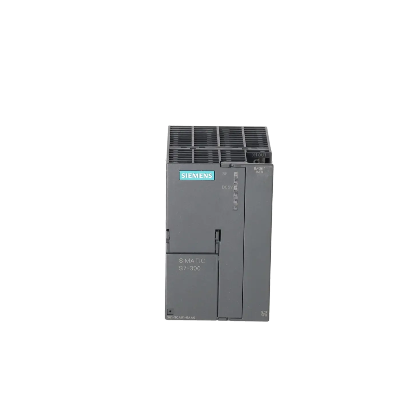
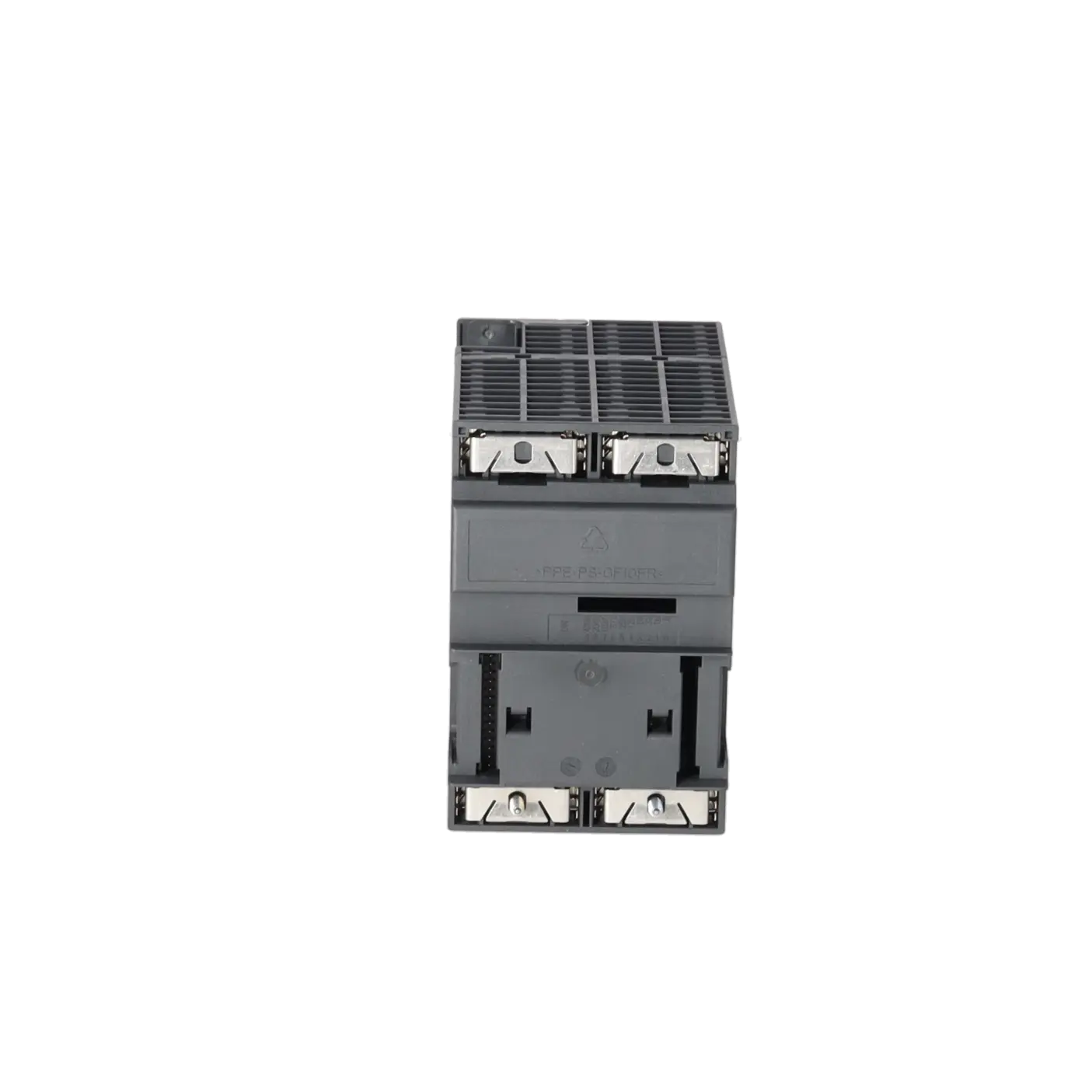
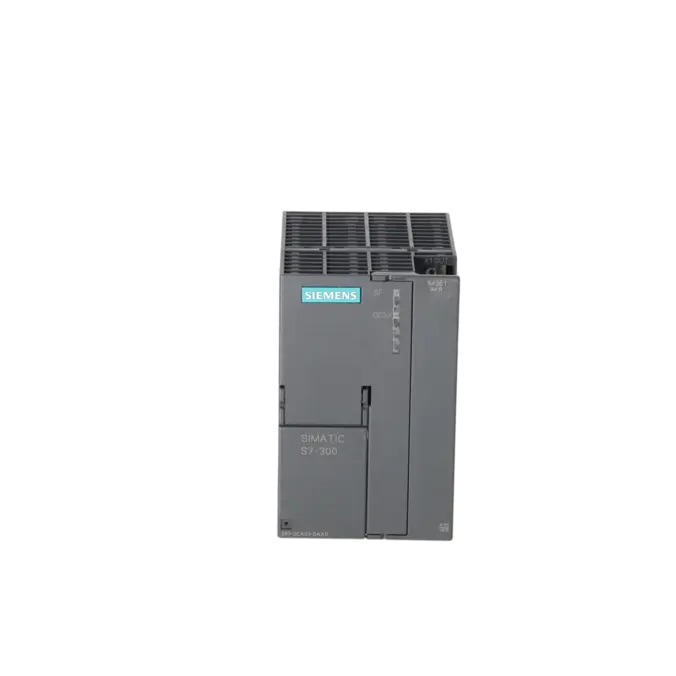
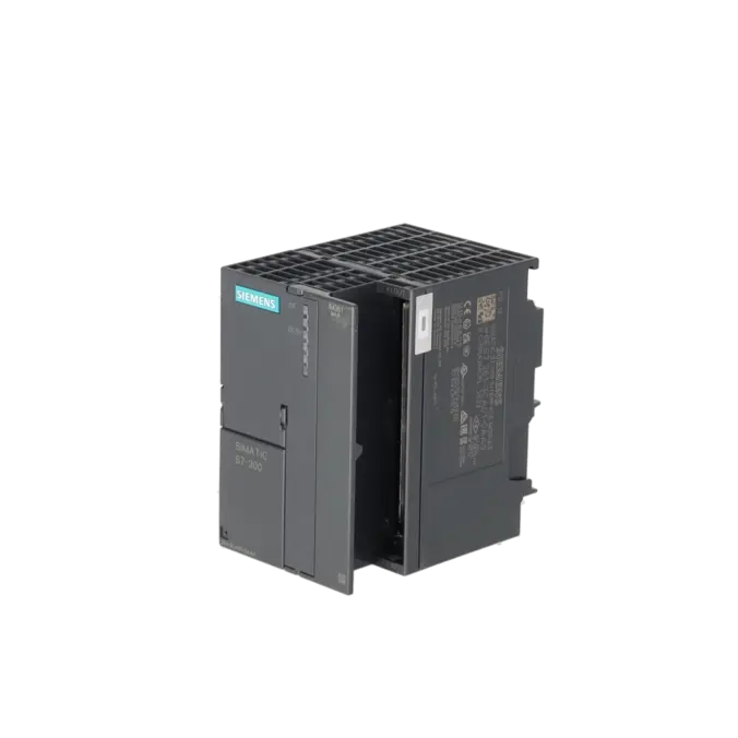
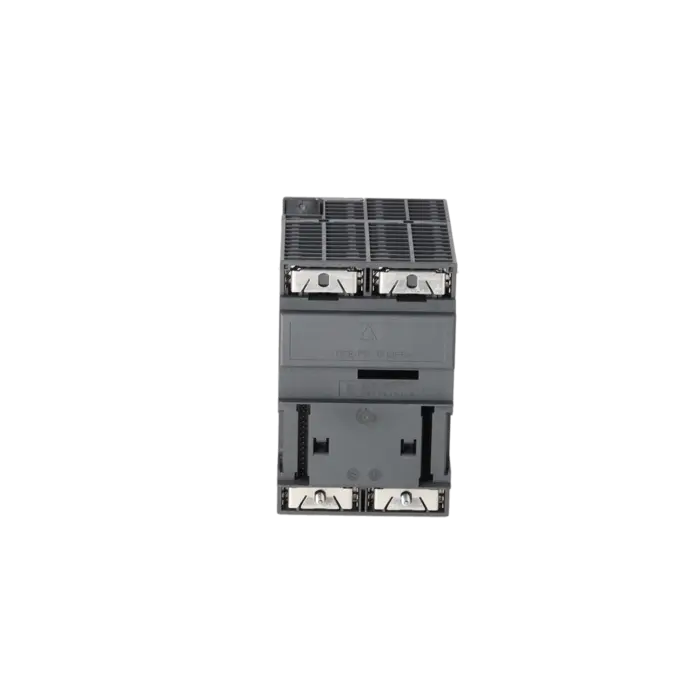
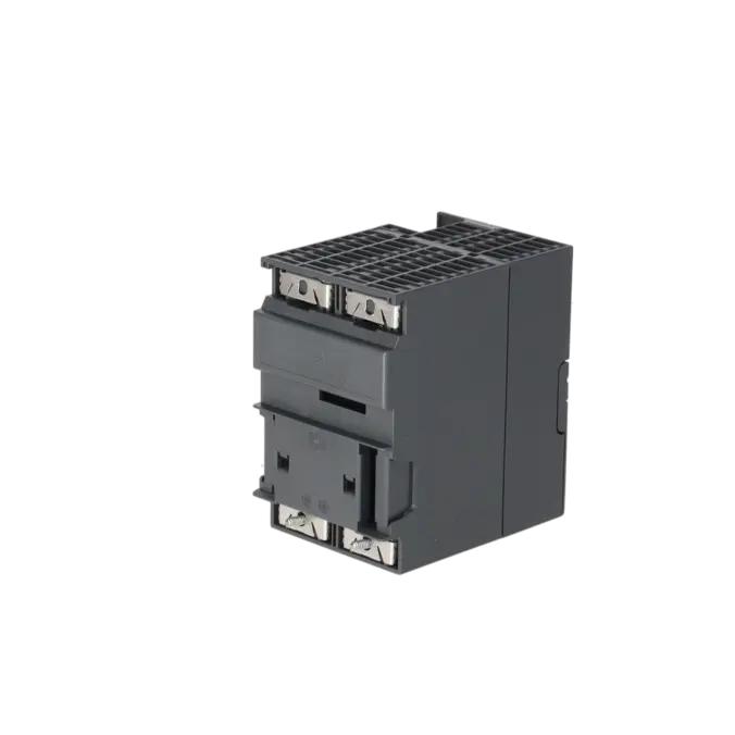
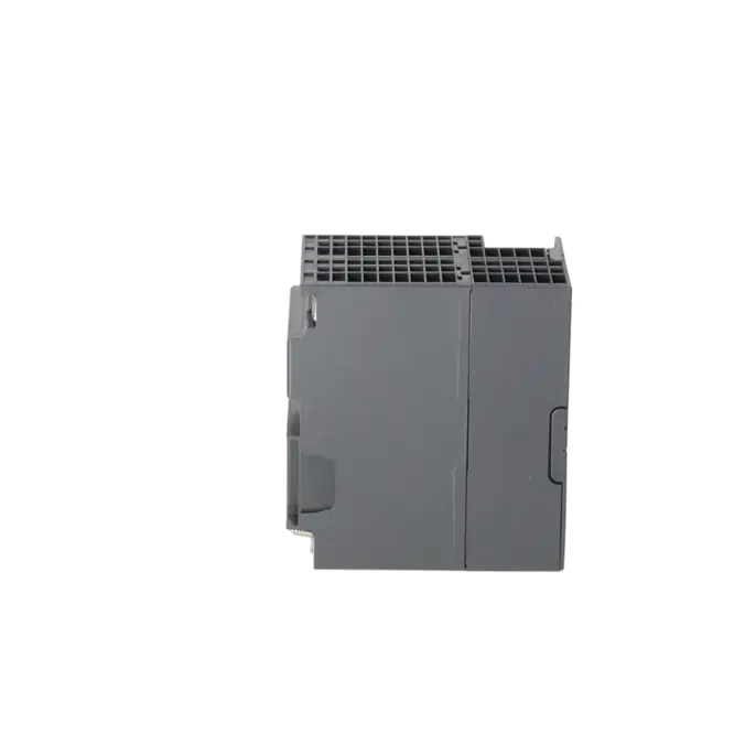
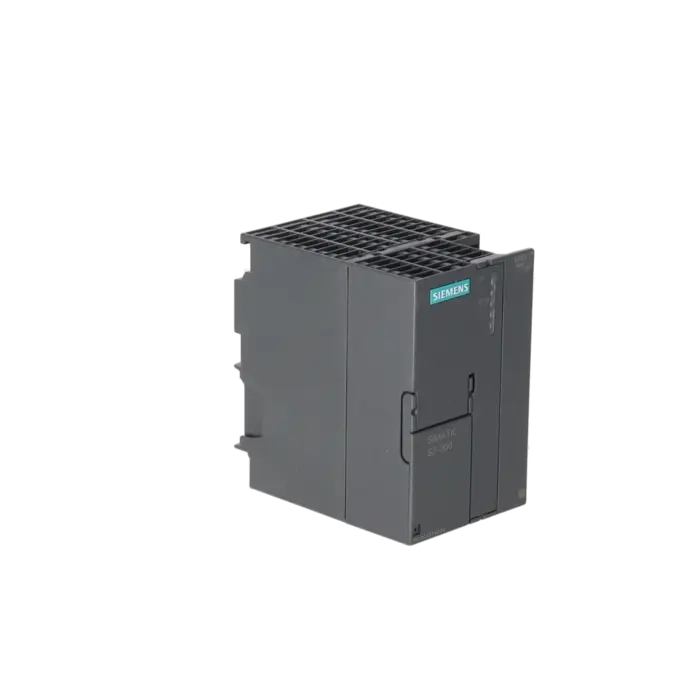
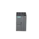
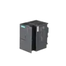
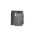
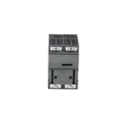
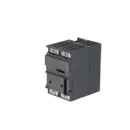
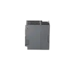
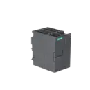
SIMATIC S7-300, CONNECTION IM 361 IN EXPANSION RACK FOR CONNECTION TO CENTRAL RACK (IM360), SUPPLY VOLTAGE 24 V DC, WITH C-BUS
Services for SIEMENS 6ES7361-3CA01-0AA0
Repair
from 227,72 €
to 409,89 €
Replacement
315,41 €
236,56 €
Used
350,47 €
262,85 €
New
SIEMENS |
6ES7361-3CA01-0AA0 –
additional product information
| Delivery information | |||
|---|---|---|---|
| Export identifier | AL: N ECCN: N | ||
| Net weight | 0.407 | ||
| Quantity | 1 Stück | ||
| Packaging quantity | 1 | ||
| Additional product information | |||
|---|---|---|---|
| Product status | EOP: 2025-10-01 | ||
| EAN | 4025515061687 | ||
| UPC | 662643176490 | ||
| Static lot number | 85389091 | ||
| List indicator | ST73 | ||
| Product group | 4564 | ||
| Country of origin | DE | ||
| Compliance with the substance restrictions according to RoHS directive | Since: 20080331 | ||
| Product classifications | Version | Classification | |
|---|---|---|---|
| eClass | 4 | 27-24-03-09 | |
| eClass | 5.1 | 27-24-22-08 | |
| eClass | 6.0 | 27-24-22-08 | |
| ETIM | 3 | / | |
| ETIM | 4 | EC001423 | |
| ETIM | 5 | EC001423 | |
What is the 6ES7361-3CA01-0AA0 and where is it used?
The 6ES7361-3CA01-0AA0 is a Siemens SIMATIC S7-300 IM 361 interface module for expansion racks. The module is not installed in the central rack; instead, it is fitted in expansion racks 1 to 3 and connects them to an IM 360 located in the central rack. This allows an S7-300 system to be expanded with additional signal modules, function modules or communication modules when there is no longer sufficient space or backplane bus capacity available in the main rack. For maintenance personnel, the IM 361 is particularly relevant when an existing installation must continue operating reliably. For procurement teams, it is important because it is often purchased specifically as a spare part for existing rack structures rather than as a conventional PLC module.
Overview of the most important technical data and what they mean
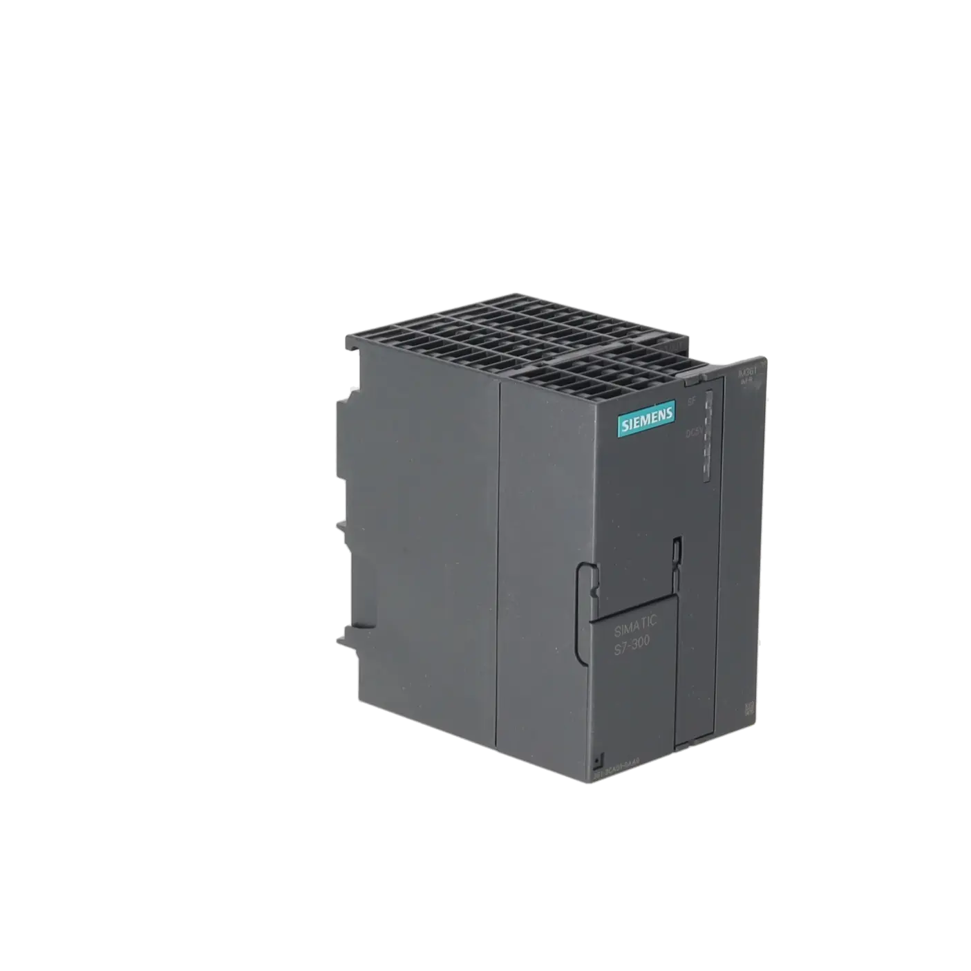
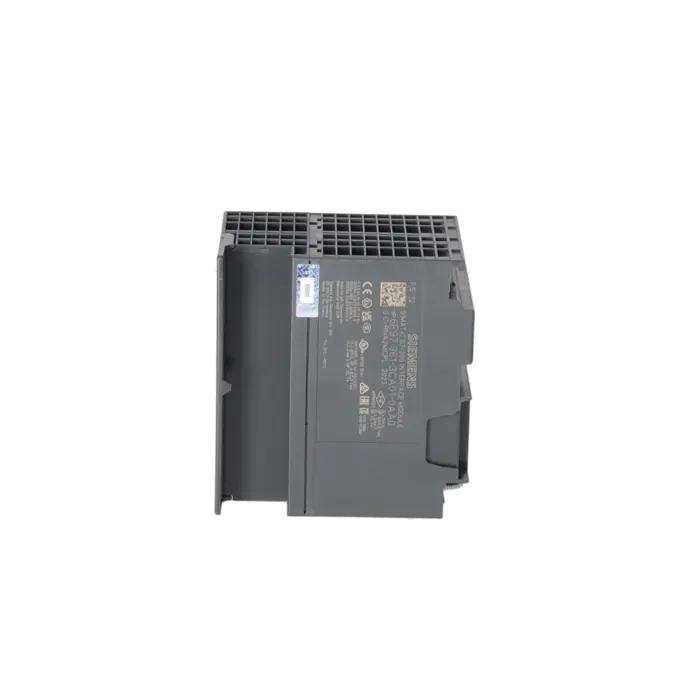
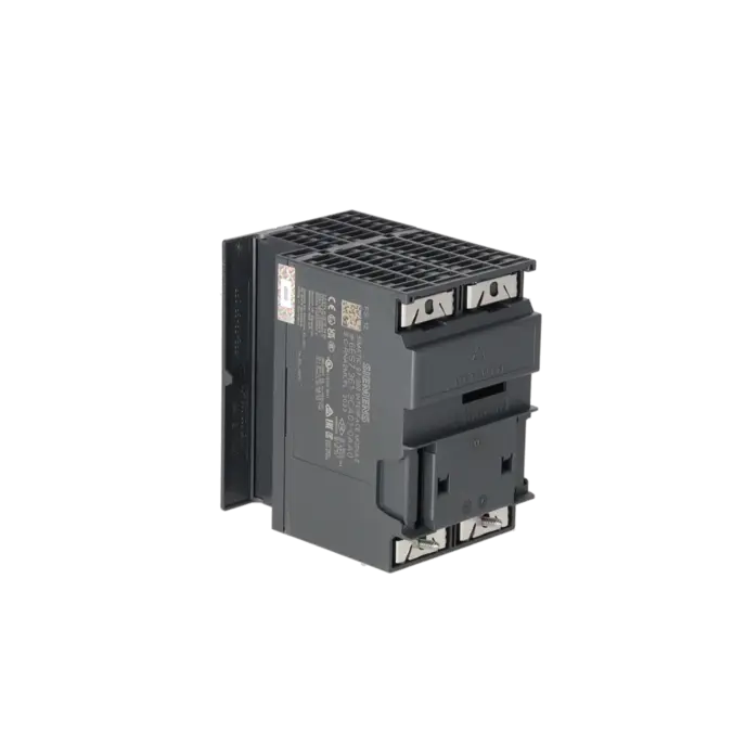
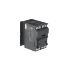
The IM 361 operates with a 24 V DC supply voltage, requires a maximum input current of 500 mA according to Siemens, and has a typical power loss of 5 W. These values are important for power supply sizing within the control cabinet and for maintaining sufficient thermal reserves in the rack. The module measures 80 × 125 × 120 mm and weighs approximately 505 g, which should be considered during tight retrofit projects or one-to-one replacements. A maximum of three interface modules per CPU can be used. In addition, the IM 361 supports a cable length of up to 10 m to the next interface module, making it suitable for distributed rack arrangements within a control cabinet or between cabinet sections. The SF and 5 VDC LEDs provide basic diagnostic information for group faults and backplane bus power supply status.
Product status, lifecycle status and obsolescence
Siemens lists the 6ES7361-3CA01-0AA0 as a spare part in the available product documentation. EICHLER additionally specifies a product status of EOP: 01 October 2025. For operators, this means that the module has clearly entered the lifecycle and obsolescence phase. It remains technically important in existing installations, but the availability of new units is likely to decrease over time, making procurement planning, spare-parts strategies and tested replacement options increasingly important. For decision-makers, this is a typical situation where downtime risk, availability and spare-parts management become more significant than simple price comparisons. Based on the publicly available manufacturer documentation reviewed, no clearly verified manufacturer-designated successor can be confirmed, and therefore none is stated here.
Available EICHLER services and when they are relevant in practice
For the 6ES7361-3CA01-0AA0, EICHLER currently offers repair, exchange, used units and new units. Repair is particularly useful when the existing installation is to remain unchanged and a form-, fit- and function-compatible return of the original module is required. According to EICHLER, the repair service includes technical cleaning, preventive maintenance, comprehensive functional testing and a minimum 24-month warranty. In the event of an unexpected production stoppage, an exchange unit is usually the faster option. For purchasing and production managers, used or new stock can be valuable when actively mitigating spare-parts risks. Especially once a product has entered the obsolescence phase, these services help maintain the operational capability of older S7-300 systems in a cost-effective and timely manner.
| Attribute | Value |
|---|---|
| Supply voltage | |
| Rated value (DC) | |
| ● 24 V DC | Yes |
| Input current | |
| from supply voltage L+, max. | 500 mA |
| Power loss | |
| Power loss, typ. | 5 W |
| Hardware configuration | |
| Number of interfaces per CPU, max. | 3 |
| Dimensions | |
| Width | 80 mm |
| Height | 125 mm |
| Depth | 120 mm |
| Weights | |
| Weight, approx. | 505 g |
| Fault description | Possible solution |
|---|---|
| Why is the SF LED on the IM 361 illuminated red? | According to Siemens, the SF LED on the IM 361 indicates a group fault. Typical causes include a missing interconnection cable, an IM 361 in the expansion chain that is switched off, or a CPU in the POWER OFF state. First check the 24 V power supply, then verify that the interconnection cable between the IM 360 and IM 361, or between two IM 361 modules, is correctly connected and securely seated. Afterwards, ensure that the CPU, the upstream interface modules, and the expansion rack are powered up and check the system using the hardware diagnostics. |
| Why is the expansion rack with IM 361 not detected in STEP 7? | In a SIMATIC S7-300 system, an IM 360 must be installed in Rack 0, while IM 361 modules must be installed in Racks 1 to 3. Within STEP 7, the interface modules must be configured in slot 3 of the respective rack. If a rack is displayed as unknown, the hardware configuration often does not match the actual installation, or the rack linkage has been configured incorrectly. In addition, check the diagnostic buffer and download the complete hardware configuration to the CPU again. |
| Why does the CPU report “Type ID does not match Actual ID” or a parameterisation fault at address 2004? | This fault pattern typically occurs when the order number, module variant or project configuration does not exactly match the installed hardware. Cases involving IM 360/361 modules have been reported in PLC forums where a parameterisation fault occurred during start-up. Therefore, verify the exact order number, the configured module version in the hardware configuration, the correct rack assignment, and that the interface module is installed in slot 3. For diagnostic purposes, it may also be useful to temporarily adjust the behaviour for configured/actual hardware mismatches in order to keep the CPU in RUN mode and obtain additional diagnostic information. |
| Why do I/O modules behind the IM 361 not operate correctly or appear with incorrect addresses? | In practice, the cause is often not the IM 361 itself but rather an addressing issue, slot assignment problem or a faulty connection cable. PLC forum discussions note that the displayed interface module address should not be confused with the actual I/O addresses of the downstream modules. A useful approach is to set addressing to the system default or assign a clearly defined start address, perform a complete cross-check of the installed modules, and test the system with a different connection cable between the IM 360 and IM 361. This helps distinguish between a module fault, a slot-related issue and a configuration error. |
Is the 6ES7361-3CA01-0AA0 a CPU or an interface module?
No. The 6ES7361-3CA01-0AA0 is not a CPU but an IM 361 interface module for the SIMATIC S7-300 system. Its function is to connect an expansion rack to the central rack; it does not execute any PLC program logic itself. This distinction is important for procurement because users often search for a CPU replacement when, in reality, only the rack interface module needs to be replaced. Correctly identifying the part number helps save time during enquiries, replacement activities and spare-parts management.
How many expansion racks can I connect using the IM 361?
With a SIMATIC S7-300 configuration using an IM 360 in the central rack and IM 361 modules in the expansion racks, up to three expansion racks can be connected. This is particularly useful when additional I/O modules, function modules or communication modules are required without immediately migrating the existing control architecture. For brownfield installations, this is often the more economical solution because the existing machine design remains unchanged and only the rack structure needs to be expanded or maintained.
Why would I use an IM 361 instead of an IM 365?
The IM 361 is used when an S7-300 system must be expanded by up to three expansion racks using the IM 360 / IM 361 architecture. The IM 365, by contrast, is intended for a different and simpler expansion concept. The key difference lies in the communication architecture: Siemens documents certain limitations for the IM 365 solution, whereas the IM 360/361 configuration is designed for typical S7-300 expansion racks requiring extended functionality. For operators of older systems, selecting the correct interface module is essential to ensure that expansion modules are compatible not only mechanically but also electrically and diagnostically.
Can I install additional modules in the expansion rack behind the IM 361?
Yes. In S7-300 expansion racks 1 to 3, slot 3 is reserved for the interface module, while slots 4 to 11 are available for signal modules, function modules or, depending on the interface configuration, communication processors. This is why the IM 361 is more than just a connection module in many existing installations: it forms the foundation that allows additional modules to be integrated into the expansion rack in a structured manner. For maintenance personnel, this is particularly important when expanding or maintaining an installation without carrying out a complete migration.
Is the 6ES7361-3CA01-0AA0 still available or only supplied as a spare part?
Siemens classifies the module as a spare part in the available product documentation, while EICHLER additionally lists an EOP date of 01 October 2025. At the same time, EICHLER continues to offer repair, exchange, used and new versions of this part number. For procurement teams, this means that the module can still be sourced, but availability increasingly depends on market stock, service capability and tested exchange options rather than on an active production programme. For production managers, this is a clear indication that spare-parts strategy and downtime prevention planning should be addressed proactively rather than postponed.