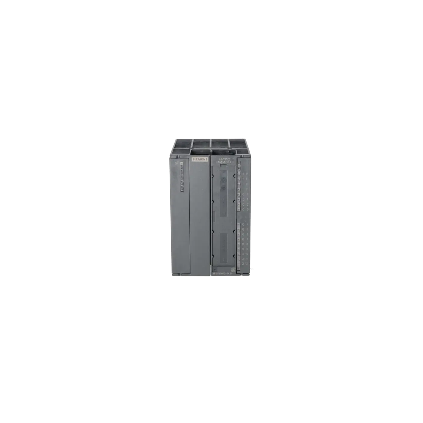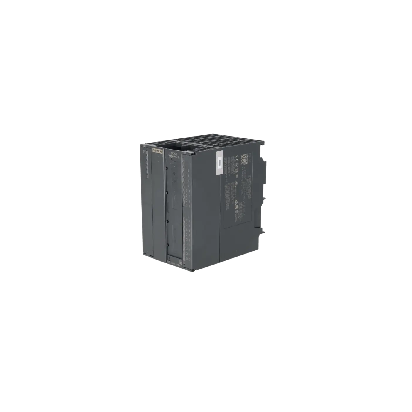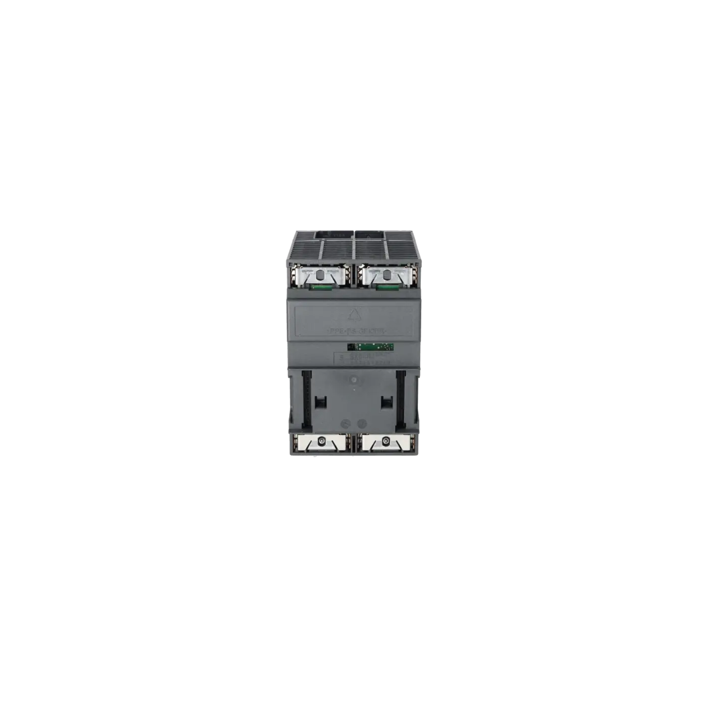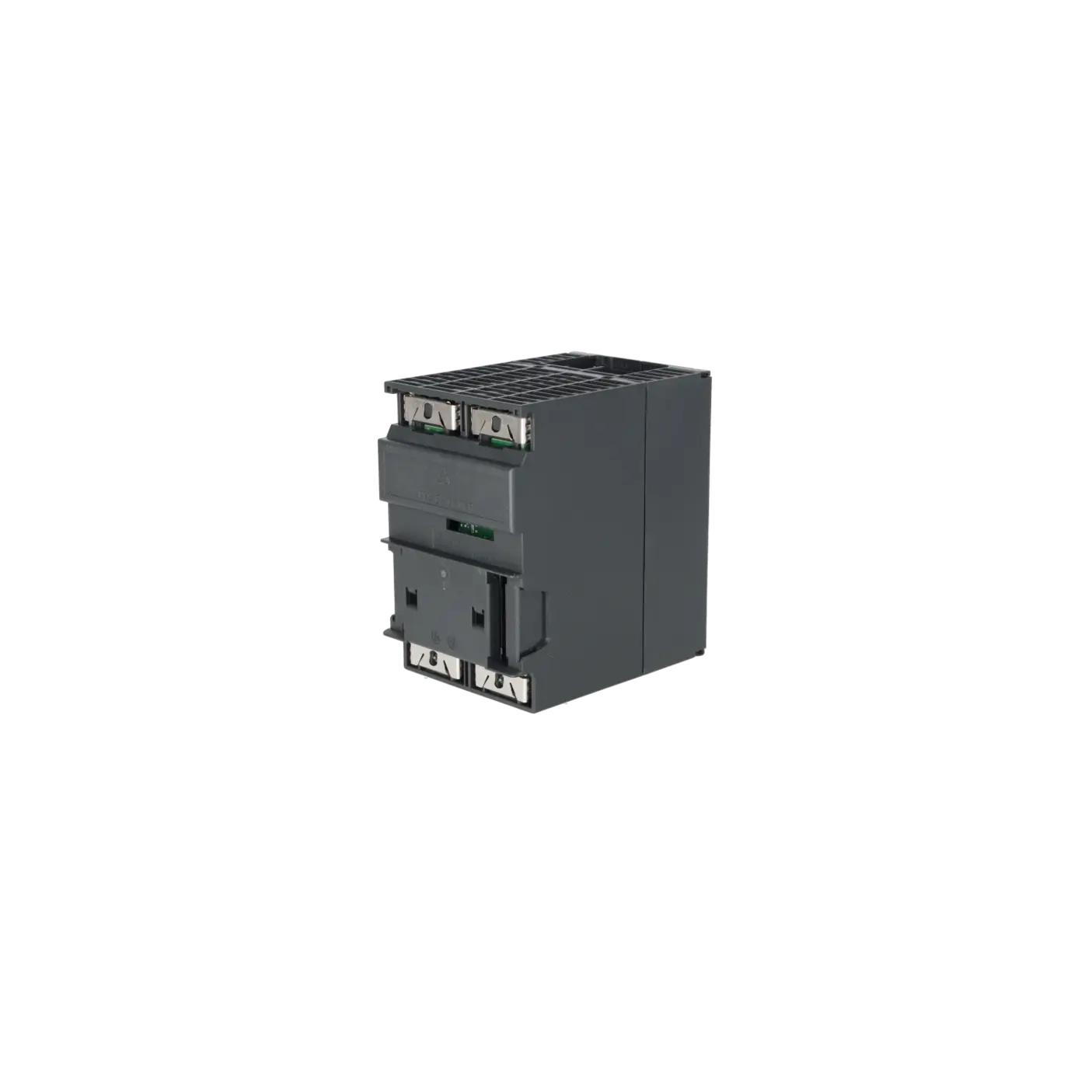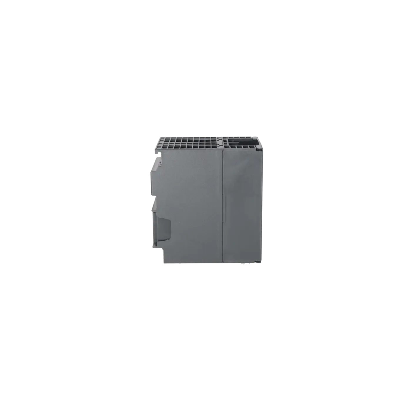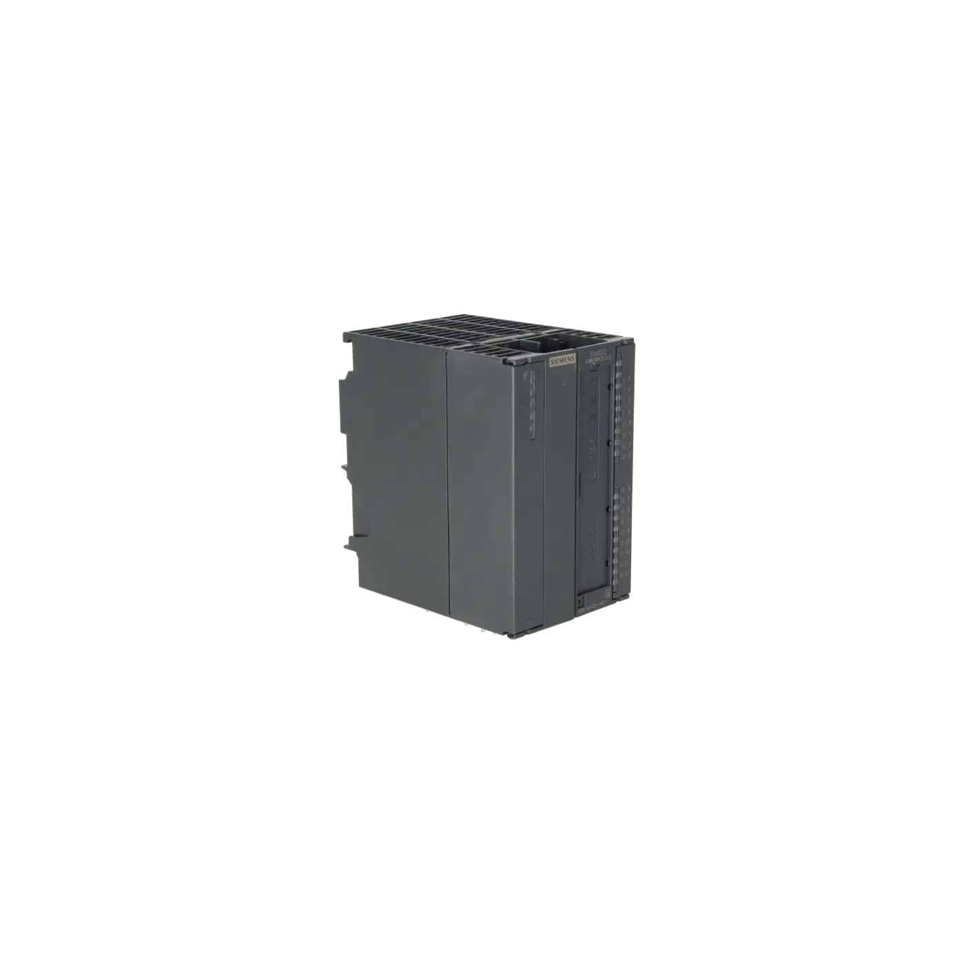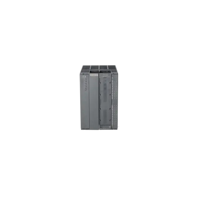
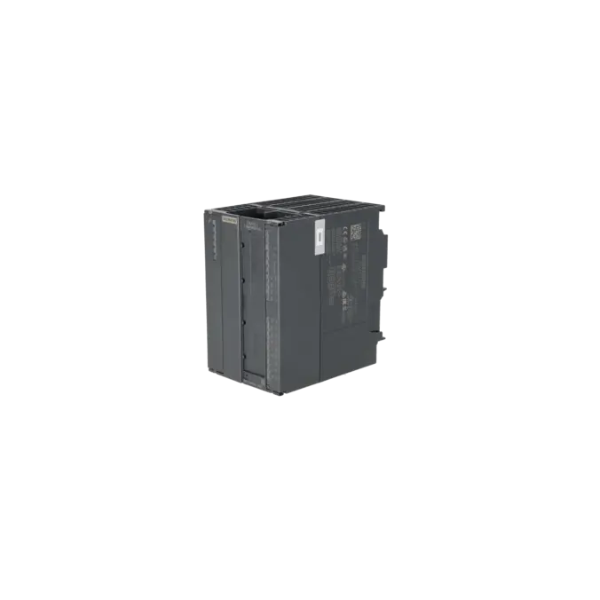
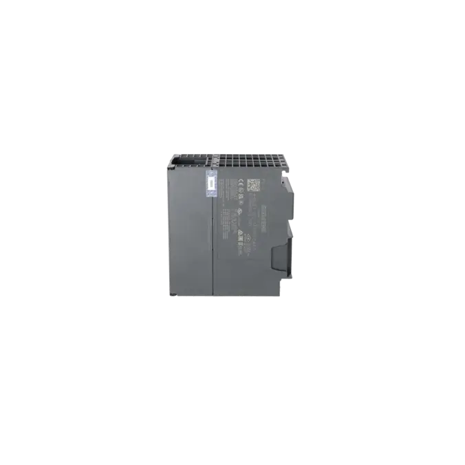
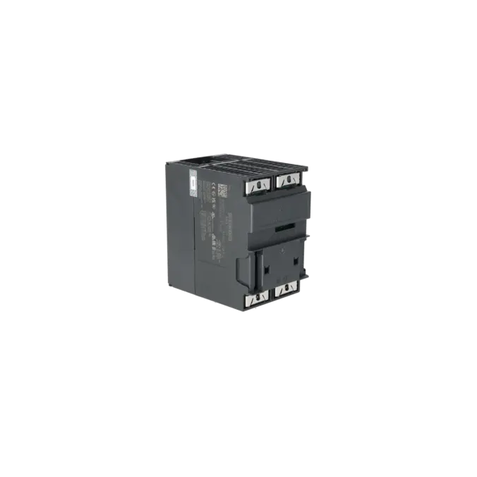
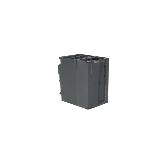


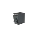


SIEMENS 6ES7352-1AH02-0AE0
- EICHLER-art.no.: K0186218
- EAN: 4025515075233
- UPC: 662643401530
Product description
SIMATIC S7-300, CAM CONTROLLER, FM 352, ELECTRONIC INCL. CONFIGURATION PACKAGE ON CD
Services for SIEMENS 6ES7352-1AH02-0AE0
Repair
from 560,88 €
to 1.009,58 €
Replacement
Used
New
1.455,30 €
1.091,47 €
SIEMENS |
6ES7352-1AH02-0AE0 –
additional product information
| Delivery information | |||
|---|---|---|---|
| Export identifier | AL: N ECCN: EAR99H | ||
| Net weight | 0.464 | ||
| Quantity | 1 Stück | ||
| Packaging quantity | 1 | ||
| Additional product information | |||
|---|---|---|---|
| Product status | |||
| EAN | 4025515075233 | ||
| UPC | 662643401530 | ||
| Static lot number | 85389091 | ||
| List indicator | ST73 | ||
| Product group | X07Y | ||
| Country of origin | DE | ||
| Compliance with the substance restrictions according to RoHS directive | Since: 20070629 | ||
| Product classifications | Version | Classification | |
|---|---|---|---|
| eClass | 4 | 27-24-03-08 | |
| eClass | 5.1 | 27-24-22-05 | |
| eClass | 6.0 | 27-24-22-05 | |
| ETIM | 3 | / | |
| ETIM | 4 | EC001422 | |
| ETIM | 5 | EC001422 | |
What is the 6ES7352-1AH02-0AE0 and where is it used?
The 6ES7352-1AH02-0AE0 is the Siemens FM 352 function module for the SIMATIC S7-300 automation platform. The module operates as a single-channel electronic cam controller. It is designed for both rotary axes and linear axes and processes signals from proximity switches, incremental encoders and SSI absolute encoders. Up to 128 position-based or time-based cams can be configured and distributed across 32 cam tracks. The first 13 tracks are available directly via the module’s digital outputs. Typical applications include presses, packaging machines, rotary indexing tables, dosing systems, adhesive application processes and other machinery where switching operations must be triggered with precise positional accuracy along an axis.
Overview of the key technical data and what it means
The module operates from 24 V DC, requiring up to 200 mA from the load supply and an additional 100 mA from the backplane bus. It provides both 5 V and 24 V encoder supplies, each capable of delivering up to 300 mA. For practical applications, the module includes 4 digital inputs for functions such as a reference-point switch, flying actual-value setting or brake release, together with 13 digital outputs assigned to the cam tracks.
The FM 352 supports:
- Symmetrical 5 V incremental encoders up to 1 MHz
- Asymmetrical 24 V incremental encoders up to 50 kHz
- SSI absolute encoders with 13-bit or 25-bit resolution
For SSI applications, the FM 352 supports Gray code. Additional cabinet-relevant specifications include an operating temperature range of 0 to 60 °C, a 20-pin front connector, and dimensions of 80 × 125 × 120 mm.
Product status, life-cycle status and obsolescence
Siemens currently classifies the 6ES7352-1AH02-0AE0 as a spare part. For operators of existing systems, this is significant because the module remains available but is clearly positioned within the late stage of its product lifecycle. The part number is also explicitly listed in an EICHLER overview of S7-300 and ET 200M modules entering the discontinuation phase from 01 October 2025.
For legacy installations, it is also important to note that Siemens has approved the 6ES7352-1AH02-0AE0 as a fully compatible successor version to the earlier 6ES7352-1AH01-0AE0.
For migration to the S7-1500 platform, Siemens does not specify a direct plug-compatible replacement. Instead, the equivalent functionality is achieved through a combination of:
- TM Count 2x24V
- TM PosInput2
- TO Cam / TO Cam Track
- TM Timer DIDQ 16x24V
This should be regarded as a functional migration strategy rather than a simple module replacement.
Available EICHLER services and when they are relevant in practice
For this part number, EICHLER offers repair, exchange, used equipment and new equipment options.
Repair is particularly appropriate when an existing machine must be returned to service quickly while retaining the current parameterisation, wiring and mechanical integration. According to EICHLER, the repair process includes:
- Technical cleaning
- Preventive maintenance
- Comprehensive functional testing
- A minimum 24-month warranty
This helps reduce the risk of subsequent unplanned failures.
An exchange service is particularly valuable when the cost of downtime exceeds the expected repair duration. Used equipment can be an effective solution where budget constraints and availability are the primary considerations. New equipment is often preferred when organisations require a fast, well-defined replacement solution for critical spare-parts inventory or preventive stockholding strategies.
| Attribute | Wert |
|---|---|
| Supply voltage | |
| Rated value (DC) | 24 V |
| Input current | |
| from load voltage L+ (without load), max. | 200 mA |
| from backplane bus 5 V DC, max. | 100 mA |
| Encoder supply | |
| 5 V encoder supply | |
| ● 5 V | Yes |
| ● Output current, max. | 300 mA |
| ● Cable length, max. | 32 m |
| 24 V encoder supply | |
| ● 24 V | Yes |
| ● Output current, max. | 300 mA |
| ● Cable length, max. | 100 m |
| Power loss | |
| Power loss, typ. | 8.1 W |
| Digital inputs | |
| Number of digital inputs | 4 |
| Functions | Reference point switch, set floating actual value/length measurement, brake release, enable track output no. 3 |
| Input voltage | |
| ● Rated value (DC) | 24 V |
| ● for signal "0" | -30 to +5 V |
| ● for signal "1" | +11 to +30V |
| Input current | |
| ● for signal "0", max. (permissible quiescent current) | 2 mA |
| ● for signal "1", typ. | 9 mA |
| Digital outputs | |
| Number of digital outputs | 13 |
| Functions | Cam track |
| Short-circuit protection | Yes |
| Output voltage | |
| ● Rated value (DC) | 24 V |
| ● for signal "1", min. | UP - 0.8 V |
| Output current | |
| ● for signal "1" permissible range for 0 to 60 °C, min. | 5 mA; with UPmax |
| ● for signal "1" permissible range for 0 to 60 °C, max. | 600 mA; with UPmax |
| ● for signal "0" residual current, max. | 0.5 mA |
| Encoder | |
| Connectable encoders | |
| ● Incremental encoder (symmetrical) | Yes |
| ● Incremental encoder (asymmetrical) | Yes |
| ● Absolute encoder (SSI) | Yes |
| ● 2-wire sensor | Yes |
| — permissible quiescent current (2-wire sensor), max. | 2 mA |
| Encoder signals, incremental encoder (symmetrical) | |
| ● Trace mark signals | A, notA, B, notB |
| ● Zero mark signal | N, notN |
| ● Input voltage | 5 V difference signal (phys. RS 422) |
| ● Input frequency, max. | 1 MHz |
| Encoder signals, incremental encoder (asymmetrical) | |
| ● Trace mark signals | A, B |
| ● Zero mark signal | N |
| ● Input voltage | 24 V |
| ● Input frequency, max. | 50 kHz; 50 kHz for 25 m cable length; 25 kHz for 100 m cable length |
| Encoder signals, absolute encoder (SSI) | |
| ● Data signal | DATA, notDATA |
| ● Clock signal | CL, notCL |
| ● Telegram length, parameterizable | 13 or 25 bit |
| ● Clock frequency, max. | 1 MHz |
| ● Gray code | Yes |
| ● Cable length, shielded, max. | 320 m; at max. 125 kHz |
| Potential separation | |
| Potential separation digital inputs | |
| ● Potential separation digital inputs | No |
| Potential separation digital outputs | |
| ● Potential separation digital outputs | No |
| Ambient conditions | |
| Ambient temperature during operation | |
| ● min. | 0 °C |
| ● max. | 60 °C |
| Ambient temperature during storage/transportation | |
| ● min. | -40 °C |
| ● max. | 70 °C |
| Connection method | |
| required front connector | 1x 20-pin |
| Dimensions | |
| Width | 80 mm |
| Height | 125 mm |
| Depth | 120 mm |
| Weights | |
| Weight, approx. | 550 g |
| Fault description | Possible solution |
|---|---|
| Why does the FM 352 report an “absolute encoder telegram error”? | First check the entire SSI communication path, including the connector, cable, shielding, encoder supply voltage and baud rate. Siemens identifies possible causes such as an incorrect encoder type, incorrect telegram length, electrical interference, an excessively high baud rate or a defective encoder. In addition, it is important to note that the FM 352 expects SSI Gray code. If the encoder format and module parameterisation do not match, cam processing is disabled and the cam-track outputs are switched off. After correcting the issue, the communication between the encoder and the FM 352 should be tested again and the diagnostics re-evaluated. |
| Why does the actual position value jump on the FM 352, or why do the direction bits change state briefly? | This type of behaviour is typically associated with incorrect encoder parameterisation or unstable SSI data transmission. A PLC forum discussion described exactly this symptom, with position-dependent value spikes attributed to a mismatch between the encoder coding and the module parameter settings. If the Gray code, telegram type, telegram length, baud rate and axis parameterisation are not configured consistently, the actual position value may become unreliable. Also check the cable shielding, earthing, connectors and the encoder itself. If the anomalies repeatedly occur at the same axis position, the mechanical condition and alignment of the encoder should also be inspected. |
| Why is the SF LED on the FM 352 permanently or intermittently illuminated? | According to Siemens, the red SF LED indicates either internal or external faults. These include, among others, lost process alarms, watchdog timeouts, missing configuration, incorrect parameterisation, missing 24 V auxiliary voltage, a missing front connector, encoder wire breaks, operating faults, absolute encoder telegram errors or false pulses from an incremental encoder. To isolate the cause correctly, OB82, the diagnostic buffer and the CAM_DIAG function block should be evaluated first. Only then should conclusions be drawn regarding the wiring, parameterisation, encoder, power supply or the module itself. |
| Why does the FM 352 not switch any cams after power-up, or why does it remain unsynchronised? | After a module or CPU start-up, the associated data structures must be correctly initialised. Siemens therefore requires execution of CAM_INIT following start-up, together with a correctly configured MOD_ADDR in the channel DB and, where applicable, in the diagnostic DB. In addition, the axis must be synchronised. With absolute encoders, the axis is only considered synchronised after a complete, error-free telegram has been received. With incremental encoders, no synchronisation exists immediately after start-up; synchronisation is only achieved following a valid referencing procedure or zero-marker evaluation. Without these prerequisites, the module remains functionally restricted. |
| Why are there problems loading parameters after replacing a 6ES7352-1AH01-0AE0 with a 6ES7352-1AH02-0AE0? | Siemens describes the 6ES7352-1AH02-0AE0 as a new, fully compatible version of the older 6ES7352-1AH01-0AE0. However, Siemens also specifies that when loading parameters using the commissioning software, the maximum number of output cams should be set to 128, even if the application requires fewer cams. In addition, the hardware configuration, function block version, module address and the associated data blocks (DBs) should be checked. For STEP 7 Professional V11 and later, Siemens also provides a sample commissioning project, which can be particularly helpful when resolving migration or parameterisation issues. |
Is the 6ES7352-1AH02-0AE0 still available or only as a spare part?
Siemens currently classifies the assembly as a spare part. For procurement and maintenance teams, this means that the module is no longer part of a current mainstream product family but may still remain available for service and spare-parts applications. According to the EICHLER product page, repair, exchange, used equipment and new equipment are currently available for this part number. This means that operators of existing S7-300 installations can continue sourcing the module without immediately having to undertake a complete migration project. For critical systems, this underlines the importance of aligning stockholding strategies, repair options and obsolescence planning at an early stage.
Which encoders can the FM 352 process?
The FM 352 supports:
- Symmetrical 5 V incremental encoders
- Asymmetrical 24 V incremental encoders
- SSI absolute encoders
- 2-wire sensors
For SSI applications, it is important to note that 13-bit and 25-bit telegrams can be parameterised and that the module supports Gray code. For maintenance personnel, this means that before replacing an encoder, it is not sufficient to verify only the connector arrangement and supply voltage; the signal type, telegram length, baud rate and data format must also be checked. For procurement teams, this is particularly important because a seemingly compatible encoder may still be unsuitable if its communication parameters do not exactly match those required by the FM 352.
How many cams and tracks can the module manage?
The FM 352 can manage up to 128 position-based or time-based cams. These can be assigned across 32 cam tracks. The first 13 tracks are available directly via the module’s digital outputs. Siemens links the number of configured cams to the module’s data volume and therefore also to the cam cycle time. This is important during engineering because increasing the number of cams can influence both the response behaviour and the internal data structures. In practice, the module is particularly well suited to applications requiring multiple position-dependent switching operations to be executed accurately, repeatedly and with predictable latency.
Can I continue to configure the 6ES7352-1AH02-0AE0 using TIA Portal or current STEP 7 documentation?
Yes. Siemens provides a sample project for commissioning the FM 352 with STEP 7 Professional V11 and later. In addition, the current Siemens documentation for STEP 7 V20 still contains a dedicated section entitled “Using the FM 352 (S7-300, S7-400)”, covering topics such as parameterisation, encoder interfaces, diagnostics and user programming. This is particularly valuable for service and retrofit projects because existing installations can continue to be supported using current documentation structures rather than relying solely on legacy manuals. For engineering teams, this reduces effort during troubleshooting, spare-parts integration and recommissioning.
Is there a direct successor to the FM 352 for SIMATIC S7-1500?
Siemens does not define a simple plug-compatible one-module successor for the FM 352/FM 452 family within the S7-1500 platform. Instead, the functionality is distributed across several modules and technology objects, including:
- TM Count 2x24V
- TM PosInput2
- TO Cam
- TO Cam Track
- TM Timer DIDQ 16x24V
This is therefore a functional migration concept, not a straightforward replacement of one module with another. For decision-makers, this is the key point: migration is entirely feasible, but it generally requires a technical reassessment of the encoder interface, cam logic and output architecture.
Can I use the FM 352 with an S7-1200?
No. According to the current Siemens STEP 7 / WinCC V20 Readme, the FM 352 (6ES7352-1AH02-0AE0) is not supported on the S7-1200 platform. This is an important consideration for operators because modernisation projects involving existing FM 352 functionality generally cannot be implemented as a simple hardware replacement with an S7-1200. Organisations planning to migrate from an S7-300 system should therefore evaluate at an early stage whether the target architecture should instead be based on an S7-1500 controller with the appropriate technology objects and technology modules. This helps avoid investment in a platform that cannot support the existing FM 352 functionality.