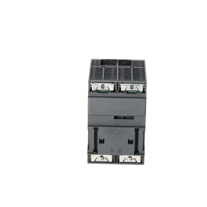
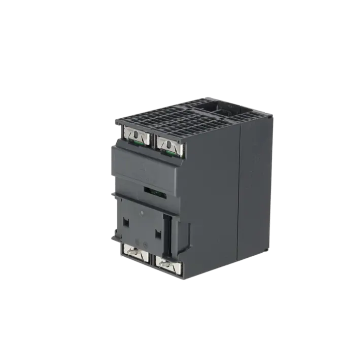
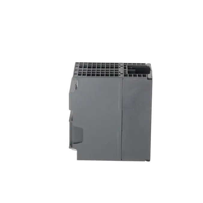
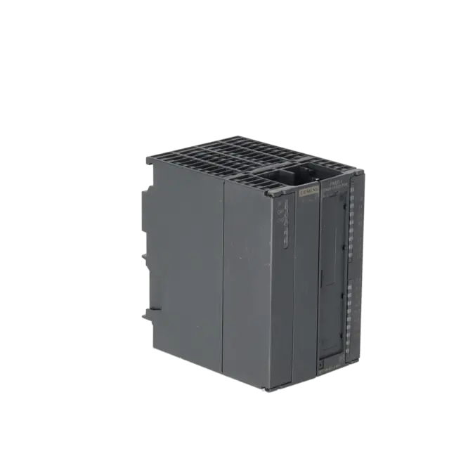


SIEMENS 6ES7351-1AH02-0AE0
-
SIEMENS | PLC Controls | Function Modules
- EICHLER-art.no.: K0252226
- EAN: 4025515078708
- UPC: 040892584790
Product description
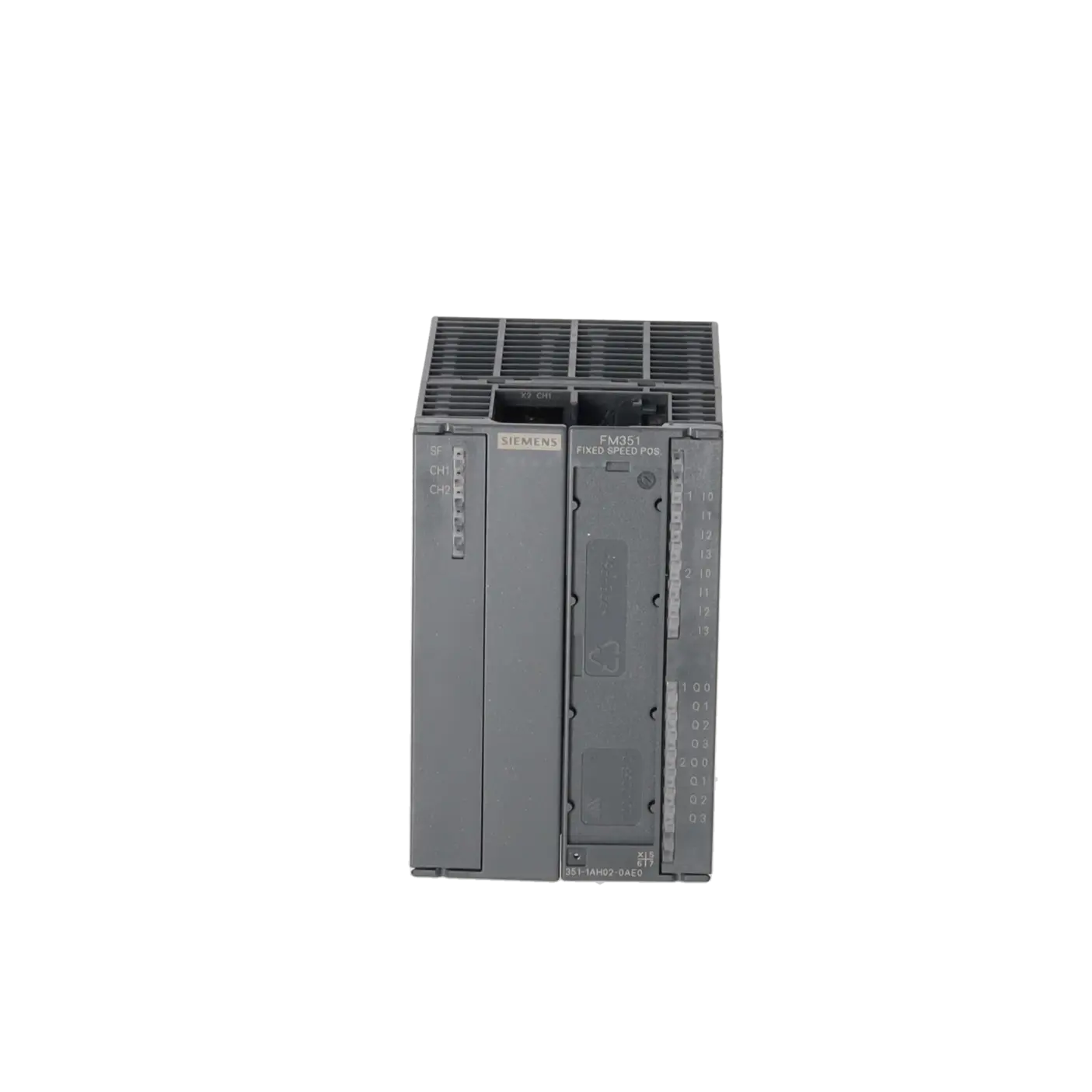
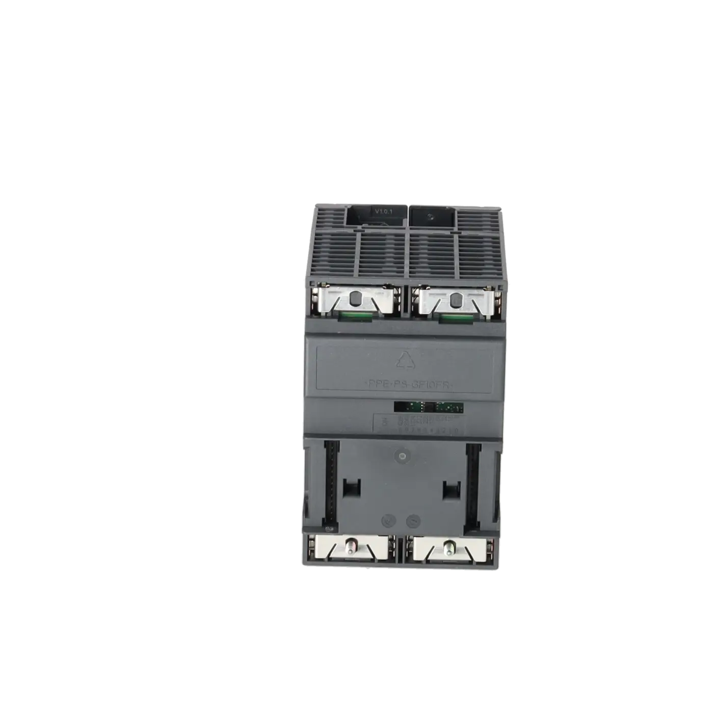
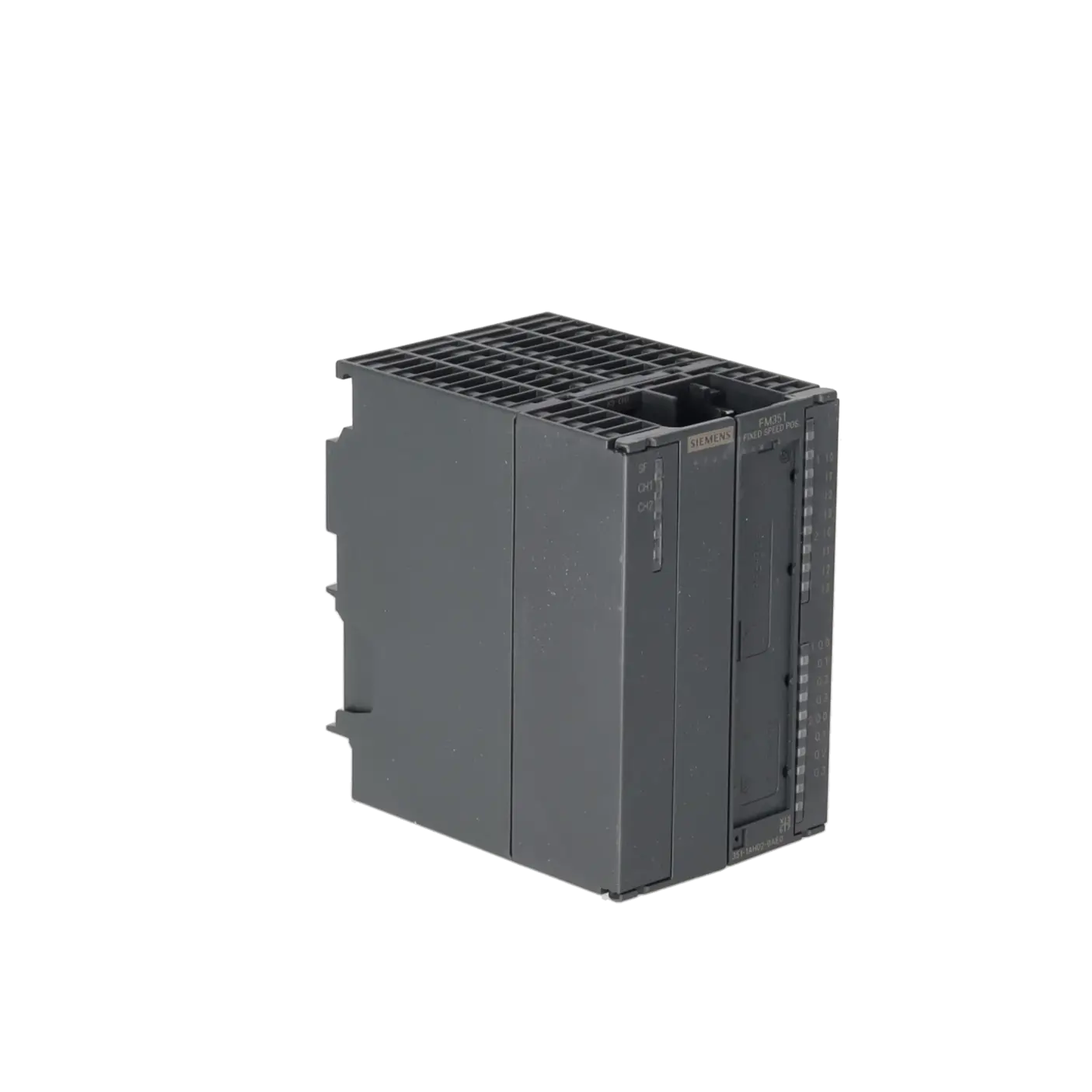
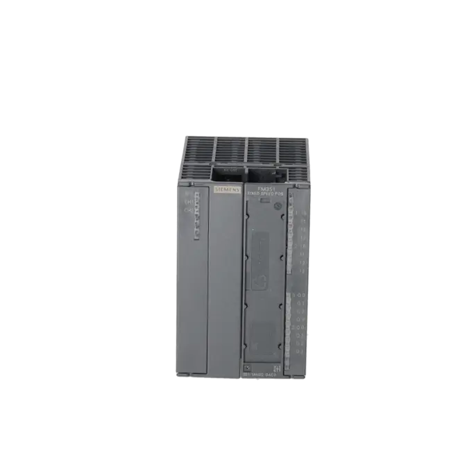
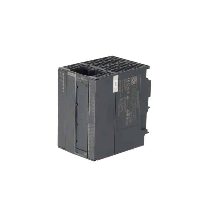
SIMATIC S7-300, POSITIONING MODULE FM 351 FOR RAPID/SLOW TRAVERSE DRIVES INCL. CONFIGURATION PACKAGE ON CD
Services for SIEMENS 6ES7351-1AH02-0AE0
Repair
from 705,18 €
to 1.037,03 €
Replacement
Used
1.066,11 €
799,58 €
New
1.382,70 €
1.037,02 €
SIEMENS |
6ES7351-1AH02-0AE0 –
additional product information
| Delivery information | |||
|---|---|---|---|
| Export identifier | AL: N ECCN: EAR99H | ||
| Net weight | 0.496 | ||
| Quantity | 1 Stück | ||
| Packaging quantity | 1 | ||
| Additional product information | |||
|---|---|---|---|
| Product status | |||
| EAN | 4025515078708 | ||
| UPC | 040892584790 | ||
| Static lot number | 85389091 | ||
| List indicator | ST73 | ||
| Product group | X07Y | ||
| Country of origin | DE | ||
| Compliance with the substance restrictions according to RoHS directive | Since: 20100831 | ||
| Product classifications | Version | Classification | |
|---|---|---|---|
| eClass | 4 | 27-24-03-08 | |
| eClass | 5.1 | 27-24-22-05 | |
| eClass | 6.0 | 27-24-22-05 | |
| ETIM | 3 | / | |
| ETIM | 4 | EC001422 | |
| ETIM | 5 | EC001422 | |
What is 6ES7351-1AH02-0AE0 and where is it used?
The SIEMENS 6ES7351-1AH02-0AE0 is a SIMATIC S7-300 FM 351 positioning assembly for rapid/creep-speed drives. It is designed to reliably perform positioning tasks in traditional automation environments, for example on linear axes, rotary axes, simple handling units, feed drives, feeding systems or movable machine axes. The assembly features two independent channels, allowing one linear or rotary axis to be controlled per channel. For feedback, each channel supports either an incremental encoder or an SSI absolute encoder. This makes the module particularly attractive for existing systems where robust PLC technology with clearly manageable positioning logic is required.
Overview of the key technical data and what it means
The assembly operates with a 24 V DC supply voltage within a permissible range of 20.4 to 28.8 V. The maximum current consumption is 350 mA, with an additional requirement of up to 150 mA via the backplane bus. Each channel provides 8 digital inputs and 8 digital outputs for typical positioning functions such as reference cam signals, start/stop, rapid traverse, creep speed, and clockwise/counter-clockwise rotation. Supported feedback devices include symmetrical and asymmetrical incremental encoders, SSI absolute encoders, and 2-wire sensors. For SSI applications, 13-bit or 25-bit telegram lengths, Gray code, and clock frequencies of up to 1.5 MHz are relevant. For maintenance personnel and purchasers, these specifications indicate which sensor technology, wiring arrangements and power supplies are compatible with the existing system without requiring additional hardware.
Product status, life cycle status and obsolescence
Siemens lists the 6ES7351-1AH02-0AE0 in the Industry Mall as a spare part. The specified Product Lifecycle Status PM410 indicates product discontinuation, effective from 01/10/2025. For operators of older S7-300 systems, this is a clear signal that long-term availability must be actively managed through repair, function-tested replacement units or strategic stockholding. A direct replacement officially designated by the manufacturer as a 1:1 successor could not be verified in the Siemens product sources reviewed. Instead, Siemens refers in its migration guide to S7-1500 technology solutions such as TM Count 2x24V or TM PosInput 2 in combination with CPU functions. This represents a migration option, but not a plug-in replacement for the FM 351.
Available EICHLER services and when they are relevant
For this assembly, EICHLER offers Repair, Exchange, Used assemblies and New assemblies. Repair is particularly suitable when the existing system still meets operational requirements, the mechanical peripherals are to remain unchanged, and a retrofit would currently introduce more risk than benefit. For repairs, EICHLER provides technical cleaning, preventive maintenance, comprehensive functional testing and a minimum 24-month warranty. This is especially important for obsolete or discontinued FM assemblies, as the objective is not only to replace a component but also to maintain the functionality of the existing axis and encoder environment. For purchasing and production departments, this provides a reliable option for reducing breakdown times and extending the economical operation of legacy systems.
| Attribute | Value |
|---|---|
| Supply voltage | |
| Rated value (DC) | 24 V |
| permissible range, lower limit (DC) | 20.4 V |
| permissible range, upper limit (DC) | 28.8 V |
| Load voltage L+ | |
| ● Rated value (DC) | 24 V |
| ● permissible range, lower limit (DC) | 20.4 V |
| ● permissible range, upper limit (DC) | 28.8 V |
| Input current | |
| Current consumption, max. | 350 mA |
| from backplane bus 5 V DC, max. | 150 mA |
| Encoder supply | |
| 5 V encoder supply | |
| ● 5 V | Yes |
| ● Output current, max. | 350 mA |
| ● Cable length, max. | 32 m |
| 24 V encoder supply | |
| ● 24 V | Yes |
| ● Output current, max. | 400 mA; Per channel |
| ● Cable length, max. | 100 m |
| Power loss | |
| Power loss, typ. | 7.9 W |
| Digital inputs | |
| Number of digital inputs | 8 |
| Functions | Reference cams, reversing cams, flying actual value setting, start/stop positioning |
| Input voltage | |
| ● Rated value (DC) | 24 V |
| ● for signal "0" | -3 to +5V |
| ● for signal "1" | +11 to +30V |
| Input current | |
| ● for signal "0", max. (permissible quiescent current) | 2 mA |
| ● for signal "1", typ. | 6 mA |
| Digital outputs | |
| Number of digital outputs | 8 |
| Functions | Rapid traverse, creep, run right, run left |
| Short-circuit protection | Yes |
| Output voltage | |
| ● Rated value (DC) | 24 V |
| ● for signal "1", min. | UP - 0.8 V |
| Output current | |
| ● for signal "1" permissible range for 0 to 60 °C, min. | 5 mA; with UPmax |
| ● for signal "1" permissible range for 0 to 60 °C, max. | 600 mA; with UPmax |
| ● for signal "0" residual current, max. | 0.5 mA |
| Encoder | |
| Connectable encoders | |
| ● Incremental encoder (symmetrical) | Yes |
| ● Incremental encoder (asymmetrical) | Yes |
| ● Absolute encoder (SSI) | Yes |
| ● 2-wire sensor | Yes |
| — permissible quiescent current (2-wire sensor), max. | 2 mA; on signal "0", max. 2 mA; on signal "1", max. 6 mA |
| Encoder signals, incremental encoder (symmetrical) | |
| ● Trace mark signals | A, notA, B, notB |
| ● Zero mark signal | N, notN |
| ● Input voltage | 5 V difference signal (phys. RS 422) |
| ● Input frequency, max. | 0.5 MHz |
| Encoder signals, incremental encoder (asymmetrical) | |
| ● Trace mark signals | A, B |
| ● Zero mark signal | N |
| ● Input voltage | 24 V |
| ● Input frequency, max. | 50 kHz; 50 kHz for 25 m cable length; 25 kHz for 100 m cable length |
| Encoder signals, absolute encoder (SSI) | |
| ● Input signal | 5 V difference signal (phys. RS 422) |
| ● Data signal | DATA, notDATA |
| ● Clock signal | CL, notCL |
| ● Telegram length, parameterizable | 13 or 25 bit |
| ● Clock frequency, max. | 1.5 MHz |
| ● Gray code | Yes |
| ● Cable length, shielded, max. | 200 m; At max. 188 kHz |
| Potential separation | |
| Potential separation digital inputs | |
| ● Potential separation digital inputs | Yes |
| Potential separation digital outputs | |
| ● Potential separation digital outputs | Yes |
| Ambient conditions | |
| Ambient temperature during operation | |
| ● min. | 0 °C |
| ● max. | 60 °C |
| Ambient temperature during storage/transportation | |
| ● min. | -40 °C |
| ● max. | 70 °C |
| Connection method | |
| required front connector | 1x 20-pin |
| Dimensions | |
| Width | 80 mm |
| Height | 125 mm |
| Depth | 120 mm |
| Weights | |
| Weight, approx. | 550 g |
| Fault description | Possible solution |
|---|---|
| Why does the FM 351 report "Axis not synchronised" or why does the incremental positioning mode not start? | Siemens states that incremental positioning is only possible when the axis is already synchronised. With incremental encoders, no synchronisation is available after start-up; synchronisation is only achieved after successful referencing or valid synchronisation. With SSI encoders, the axis is considered synchronised only after a complete, error-free telegram has been received. Therefore, first check the encoder power supply, telegram quality, parameterisation, and the correct execution of the referencing or initialisation procedure. |
| Why does the FM 351 sporadically lose the synchronisation signal when using an SSI encoder? | Siemens identifies several possible causes of synchronisation loss, including a missing auxiliary voltage supply, reference mark errors, cable faults in 5 V encoder signals, or operation outside the permitted travel range. In addition, users in the PLC forum recommend checking the encoder power supply, shielding and cabling, and reducing the baud rate, as incomplete or disturbed SSI telegrams can interrupt synchronisation. Therefore, systematically check the power supply, shielding, cable routing, sources of interference, and the configured baud rate. |
| Why does the FM 351 report an error on the absolute encoder or the SSI telegram? | According to Siemens, this error occurs when communication between the FM 351 and the absolute encoder is faulty or interrupted. Typical causes include disconnected or damaged encoder cables, an incorrectly parameterised encoder type, an incorrect telegram length, incorrect encoder configuration, invalid encoder values, interference on the measuring system cable, or an excessively high baud rate. Therefore, check the encoder type, telegram length, parity, baud rate, and the physical connection all the way to the encoder. |
| Why do false pulses or reference mark errors occur with an incremental encoder? | Siemens lists several typical causes, including incorrectly configured increments per encoder revolution, a faulty encoder, a missing or defective reference mark, and electrical interference on the encoder cable. Siemens also notes that when using 5 V incremental encoders without reference marks, the wire-break monitoring must be disabled or N and /N must be externally interconnected. Therefore, check the increment parameterisation, the encoder itself, the reference mark signals, and the cable shielding. |
| Why does positioning stop with the message "External auxiliary voltage missing"? | Siemens identifies several possible causes, including a disconnected or failed 24 V auxiliary voltage supply, a defective fuse on the assembly, undervoltage, a broken ground wire, or a short circuit on the connected encoder. In this condition, positioning is aborted on all channels, the outputs are switched off, and synchronisation may be lost when using incremental encoders. Therefore, first check the 24 V connection, the wiring of 1L+/1M and 2L+/2M, the fuse, and any possible short circuits in the encoder circuit. |
What is the 6ES7351-1AH02-0AE0 used for in practice?
The assembly is used for positioning tasks with rapid traverse and creep speed, wherever axes are moved using robust PLC-based positioning logic rather than a complex servo control system. Typical applications include linear positioning systems, rotary positioning systems, feed axes, feeding systems, and legacy machines based on the S7-300 architecture. The key advantage lies in its seamless integration into existing systems and the clear separation between the PLC, the positioning logic, and the connected drive system.
Which encoders can I connect to the FM 351?
The FM 351 supports symmetrical incremental encoders, asymmetrical incremental encoders, SSI absolute encoders, and 2-wire sensors. For SSI encoders, parameters such as 13-bit or 25-bit telegram lengths, Gray code, and suitable clock frequencies are relevant. For users, this means that encoder selection must match the assembly not only mechanically but also electrically and in terms of parameterisation. Especially in retrofit or spare parts projects, it is important to verify that the existing encoder type, signal levels, cable length, and telegram parameters are compatible with the FM 351.
Is 6ES7351-1AH02-0AE0 still available or has it already been discontinued?
Siemens classifies the assembly as a spare part and specifies the lifecycle status PM410 – Product cancellation, effective from 01/10/2025, in the Industry Mall. This clearly places the module within the scope of obsolescence management. For operators, this does not automatically mean the immediate end of serviceability, but procurement becomes a planning issue. Anyone operating a critical machine with an FM 351 should secure repair options, a spare parts strategy, and, where appropriate, strategic stockholding at an early stage.
Is there a direct Siemens successor for the FM 351?
A direct 1:1 successor to the FM 351 could not be verified in the Siemens product sources reviewed. Instead, Siemens outlines migration paths to the S7-1500 platform in its official migration guide, for example through TM Count 2x24V or TM PosInput 2 combined with software functions within the CPU. This is an important consideration for decision-makers: there is a defined migration path, but there is no simple plug-and-play replacement module that can replace the FM 351 without engineering effort.
Can I commission the FM 351 with STEP 7 Professional or in TIA Portal?
Yes. Siemens provides an official support document that explicitly describes an example project for STEP 7 Professional V11 and TIA Portal V11 or later. For maintenance and engineering teams, this is important because existing FM 351 applications can be documented and reproducibly migrated into modern engineering environments. Nevertheless, the FM 351 remains a legacy assembly from the S7-300 platform, making correct hardware parameterisation, suitable HSP/support package versions, and the proper integration of the supplied example blocks essential.
When is repair more sensible than replacement or migration?
Repair is particularly economical when the mechanical components, wiring, encoders, and PLC environment of the existing system are intended to remain unchanged, and a migration to new technology would introduce additional downtime. On the EICHLER website, repair is described as including technical cleaning, preventive maintenance, functional testing, and a minimum 24-month warranty. For a discontinued FM assembly, this can be the most practical solution for avoiding downtime, reducing procurement risks, and continuing to operate the existing machine without immediate re-engineering.