SIEMENS 6ES7326-2BF41-0AB0
-
SIEMENS | PLC Controls | Digital Input / Output Modules
- EICHLER-art.no.: K0252222
- EAN: 4025515078241
- UPC: 040892550375
Product description
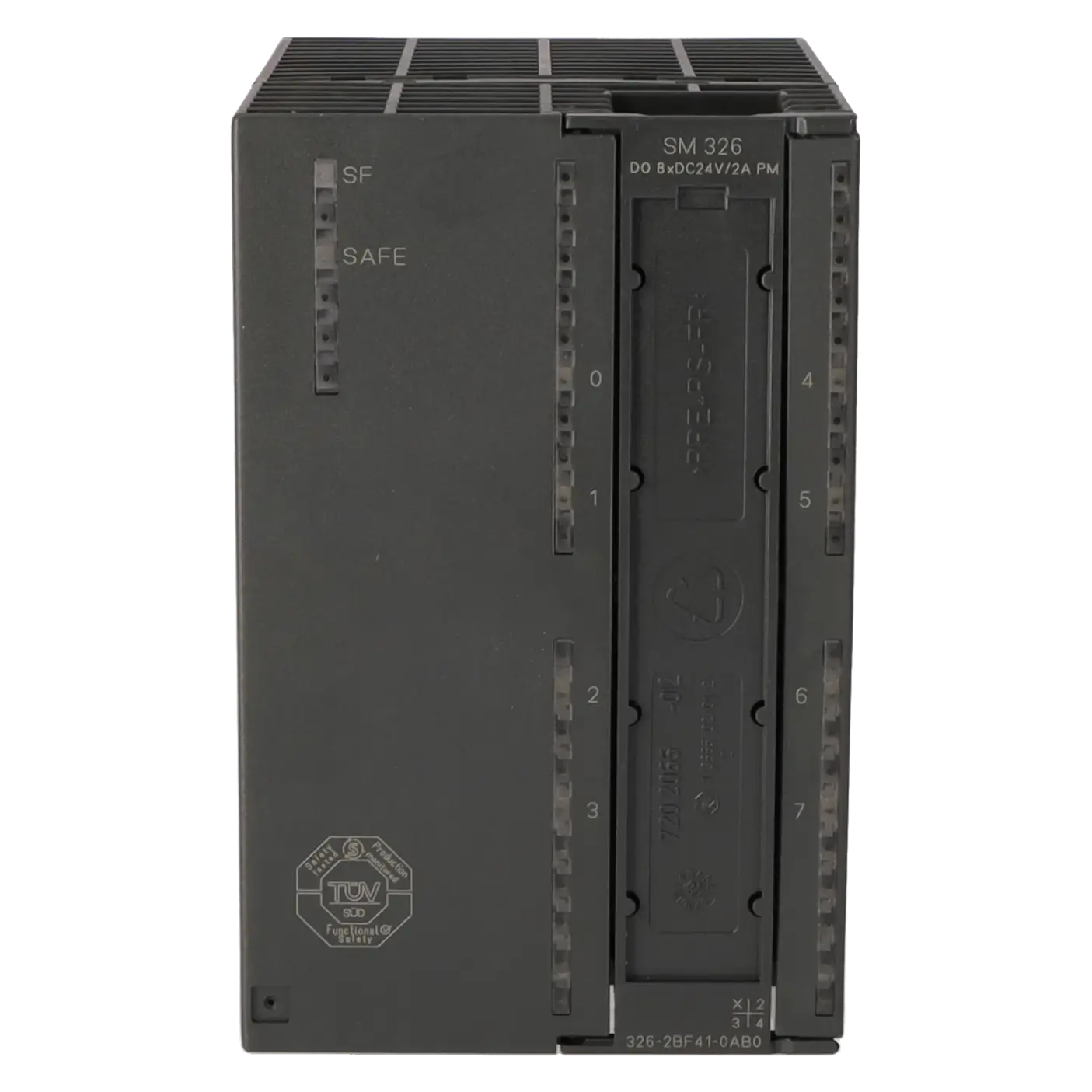
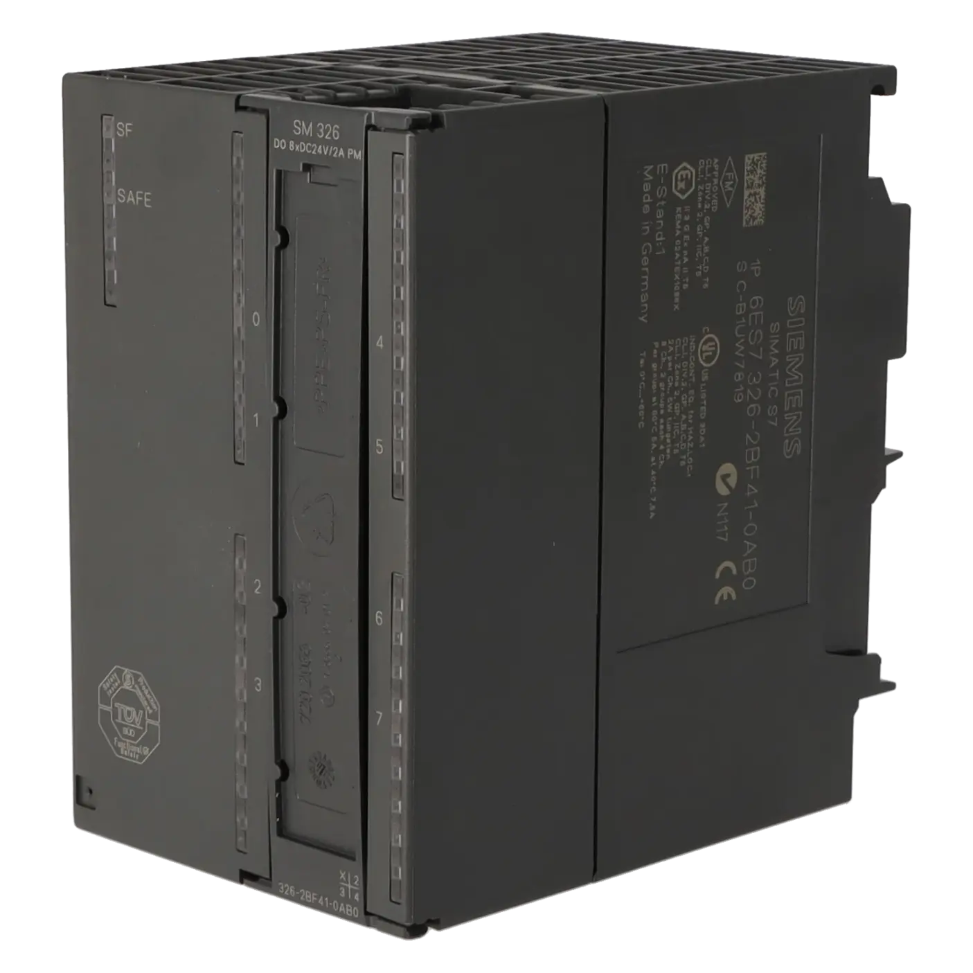
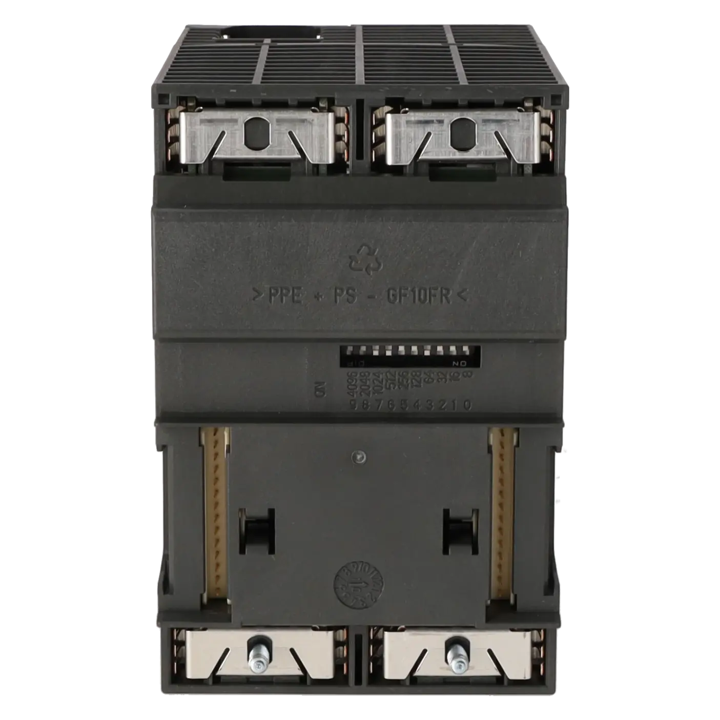
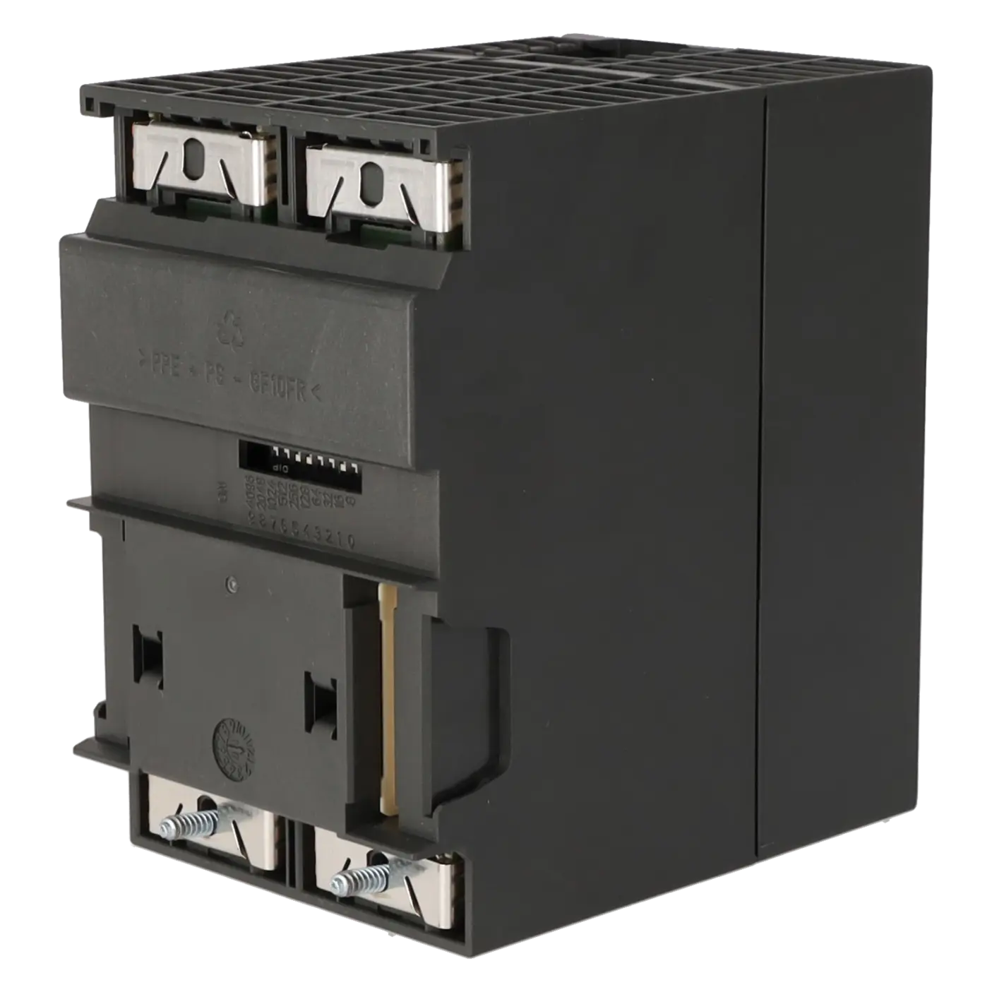
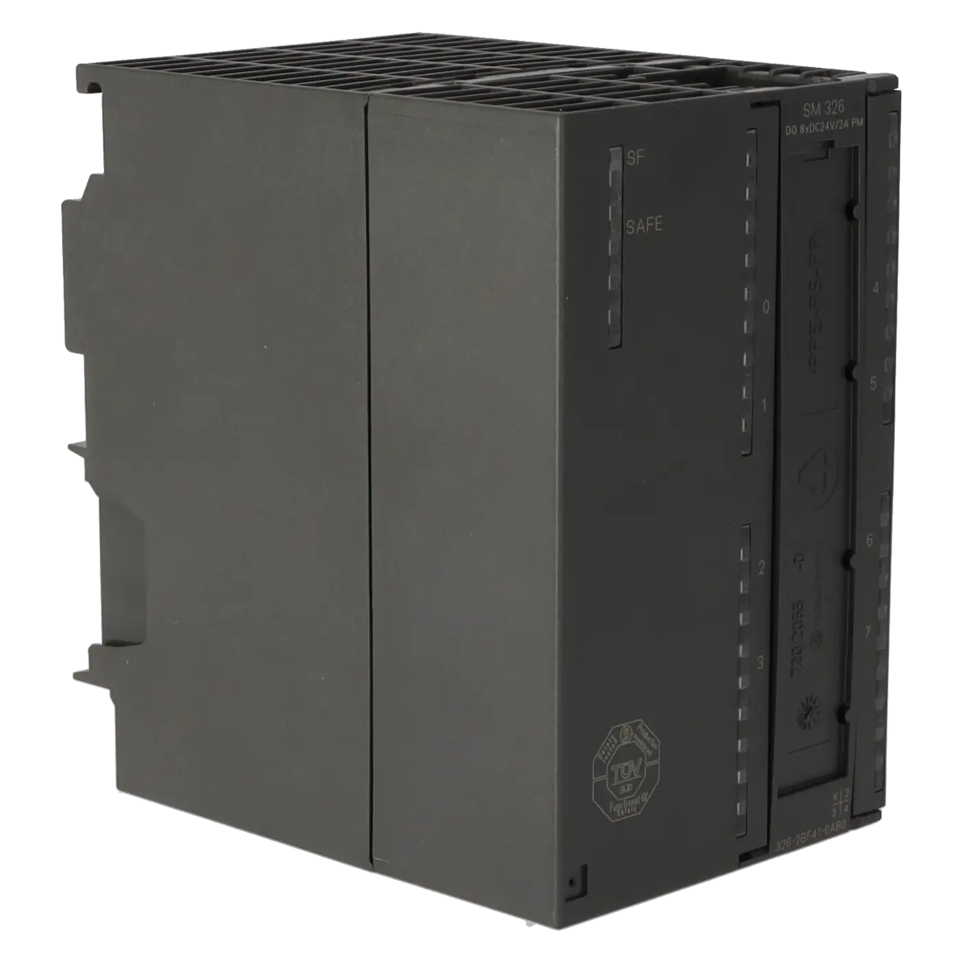
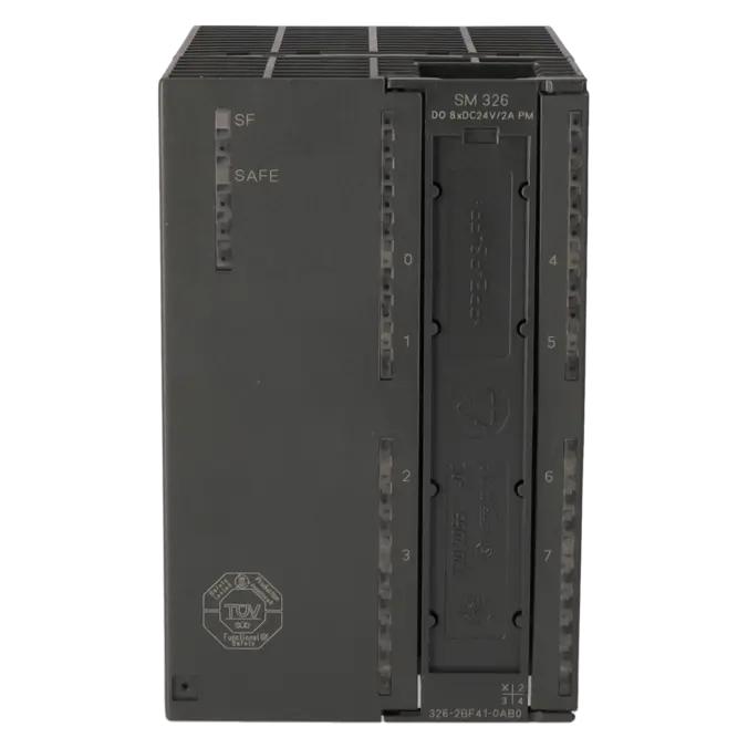
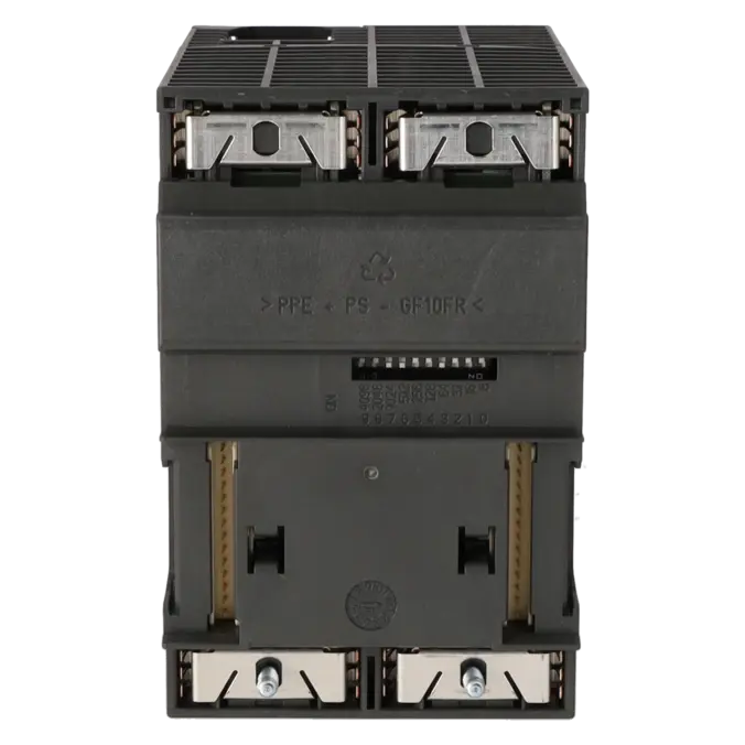
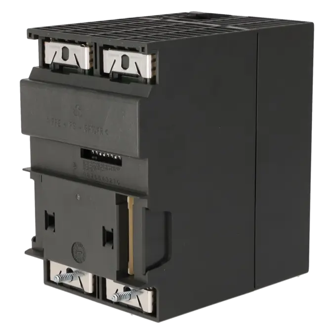
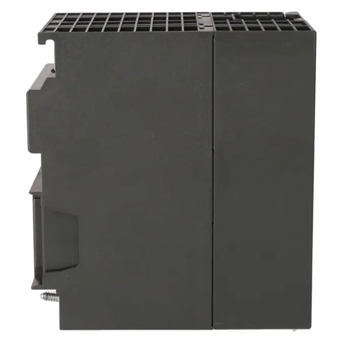
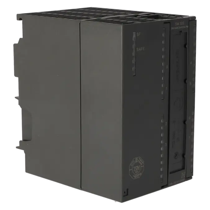
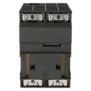
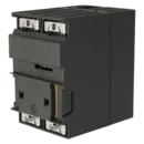
SIMATIC S7, DIGITAL OUTPUT SM 326, F-DO 8X24 V DC/2A PM FAIL-SAFE DIGITAL OUTPUT SWITCHING TO P-M POTENTIAL UP TO CATEGORY 4 (EN 954-1)/ SIL3 (IEC61508)/PLE (ISO13849), 1X 40-POLE
Services for SIEMENS 6ES7326-2BF41-0AB0
Repair
from 766,33 €
to 1.126,95 €
Replacement
826,03 €
619,52 €
Used
1.158,55 €
868,91 €
New
1.502,60 €
1.126,95 €
SIEMENS |
6ES7326-2BF41-0AB0 –
additional product information
| Delivery information | |||
|---|---|---|---|
| Export identifier | AL: N ECCN: EAR99H | ||
| Net weight | 0.501 | ||
| Quantity | 1 Stück | ||
| Packaging quantity | 1 | ||
| Additional product information | |||
|---|---|---|---|
| Product status | |||
| EAN | 4025515078241 | ||
| UPC | 040892550375 | ||
| Static lot number | 85389091 | ||
| List indicator | ST73 | ||
| Product group | 4465 | ||
| Country of origin | DE | ||
| Compliance with the substance restrictions according to RoHS directive | Since: 20091125 | ||
| Product classifications | Version | Classification | |
|---|---|---|---|
| eClass | 4 | 27-24-21-05 | |
| eClass | 5.1 | 27-24-22-04 | |
| eClass | 6.0 | 27-24-22-04 | |
| ETIM | 3 | / | |
| ETIM | 4 | EC001419 | |
| ETIM | 5 | EC001419 | |
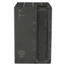
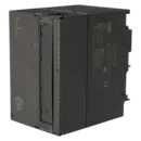
What is the 6ES7326-2BF41-0AB0 and where is it used?
The 6ES7326-2BF41-0AB0 is a failsafe digital output module from Siemens for the SIMATIC S7-300 platform. The module provides 8 digital 24 V DC outputs with up to 2 A per channel and is designed for safety-related applications. It is used wherever actuators must be reliably switched off or controlled in a defined manner in the event of a fault, for example contactors, valves, relays, interlocks or shutdown circuits in machines and process plants. As an F-DO 8xDC 24V/2A PM module, it is particularly relevant for existing S7-300 and ET 200M installations where secure spare-parts availability, rapid replacement or repair are more important than an immediate migration to a newer platform.
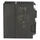
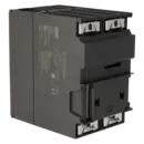
Overview of the most important technical data and what it means
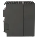
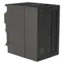
The module operates on 24 V DC and requires 1L+ for the electronics supply as well as 2L+ and 3L+ for the load voltages. It provides 8 safety-related outputs, integrated short-circuit protection and a typical power loss of 12 W. Electrical isolation is provided between channels, the backplane bus and the electronics supply. For practical applications, the output current is 2 A per channel at 0–40 °C in a horizontal installation position. In a vertical installation position, the maximum current is reduced to 1 A per channel. At temperatures between 40 °C and 60 °C, the permissible output current is also limited to 1 A. The module requires a 40-pin front connector, measures 80 × 125 × 120 mm, weighs approximately 465 g, and achieves Category 4 / PL e / SIL 3 safety performance. These values are particularly important for purchasing departments because they directly determine suitability, installation conditions and load capacity.
Product status, life-cycle status and obsolescence
For procurement and asset-management purposes, Siemens currently classifies the 6ES7326-2BF41-0AB0 explicitly as a spare part. The Siemens SiePortal additionally lists the lifecycle status as Product Cancellation. This clearly places the module within the area of advanced installed-base support and obsolescence management. It has also been verified that the 6ES7326-2BF41-0AB0 is the spare-parts-compatible successor to the earlier 6ES7326-2BF40-0AB0. For operators of existing installations, this means that maintaining safe operation increasingly depends on strategic spare-parts procurement, tested exchange units, repair capabilities and a robust stockholding strategy rather than on redesigning the system. At this stage of the product life cycle, documented service processes and quality-assured inventory become especially important.
Available EICHLER services and when they are relevant
For the 6ES7326-2BF41-0AB0, EICHLER offers several options to minimise downtime in existing installations: repair services with a typical turnaround time of 2–5 days, as well as exchange units, used units and new units with typical availability of 1–3 days. Repairs include technical cleaning, preventive maintenance, comprehensive functional testing and a minimum 24-month warranty. Product-related information also references warranty coverage of up to 36 months. For maintenance teams, this is particularly valuable when an already validated safety architecture must remain unchanged. For purchasing departments, it provides a practical choice between new equipment, used equipment and repair. For decision-makers, the availability of these service options significantly reduces the risk of unplanned modifications when an obsolescent failsafe module must be returned to service quickly.
| Attribute | Value |
|---|---|
| Supply voltage | |
| Rated value (DC) | 24 V; 1L+ |
| Reverse polarity protection | Yes |
| Load voltage L+ | |
| ● Rated value (DC) | 24 V; 2L+, 3L+ |
| ● Reverse polarity protection | No |
| Input current | |
| from supply voltage 1L+, max. | 75 mA |
| from load voltage 2L+ (without load), max. | 100 mA |
| from load voltage 3L+ (without load), max. | 100 mA |
| from backplane bus 5 V DC, max. | 100 mA |
| Power loss | |
| Power loss, typ. | 12 W |
| Digital outputs | |
| Number of digital outputs | 8 |
| Short-circuit protection | Yes |
| Limitation of inductive shutdown voltage to | L+ (-33 V) |
| Switching capacity of the outputs | |
| ● on lamp load, max. | 5 W |
| Output voltage | |
| ● for signal "1", min. | L+ (-1.0 V) |
| Output current | |
| ● for signal "1" rated value | 2 A |
| ● for signal "1" permissible range for 0 to 40 °C, min. | 7 mA |
| ● for signal "1" permissible range for 0 to 40 °C, max. | 2 A; 2 A for horizontal installation, 1 A for vertical installation |
| ● for signal "1" permissible range for 40 to 60 °C, min. | 7 mA |
| ● for signal "1" permissible range for 40 to 60 °C, max. | 1 A; for horizontal installation |
| ● for signal "0" residual current, max. | 0.5 mA |
| Switching frequency | |
| ● with resistive load, max. | 30 Hz |
| ● with inductive load, max. | 2 Hz |
| ● on lamp load, max. | 10 Hz |
| Total current of the outputs (per group) | |
| horizontal installation | |
| — up to 40 °C, max. | 7.5 A |
| — up to 60 °C, max. | 5 A |
| vertical installation | |
| — up to 40 °C, max. | 5 A |
| Cable length | |
| ● shielded, max. | 200 m; 200 m for SIL 3, AK 6, Cat 4 |
| ● unshielded, max. | 200 m |
| Interrupts/diagnostics/status information | |
| Alarms | |
| ● Diagnostic alarm | Yes; Parameterizable |
| Diagnoses | |
| ● Diagnostic information readable | Yes |
| Diagnostics indication LED | |
| ● Fail-safe operation | Yes |
| ● Group error SF (red) | Yes |
| Potential separation | |
| Potential separation digital outputs | |
| ● between the channels | Yes |
| ● between the channels, in groups of | 4 |
| ● between the channels and backplane bus | Yes |
| ● between the channels and the power supply of the electronics | Yes |
| Isolation | |
| Isolation tested with | 500 V DC/350 V AC |
| Standards, approvals, certificates | |
| Highest safety class achievable in safety mode | |
| ● acc. to EN 954 | Cat. 4 |
| ● Performance level according to ISO 13849-1 | e |
| ● SIL acc. to IEC 61508 | SIL 3 |
| Connection method | |
| required front connector | 40-pin |
| Dimensions | |
| Width | 80 mm |
| Height | 125 mm |
| Depth | 120 mm |
| Weights | |
| Weight, approx. | 465 g |
| Fault description | Possible solution |
|---|---|
| Why are the safety outputs of the 6ES7326-2BF41-0AB0 not being activated? | First check whether the F runtime group is active, whether the assembly has been parameterised correctly and whether an SF fault is present on the CPU or the assembly. In one documented practical case, the cause was not the safety program but reversed wiring of A1 and A2. In addition, the load voltages, enable conditions and safety-related configuration should be checked. |
| Why does the 6ES7326-2BF41-0AB0 report “short circuit on the load voltage”? | If the parameterisation is correct, wiring faults, freewheeling diodes or RC circuits connected in parallel to the relay coil, as well as incorrectly connected load voltage, should be checked. In one documented case, the cause was also found in the wiring rather than in the assembly itself. Therefore, carefully inspect the load circuit, wiring and connected actuators before considering the assembly defective. |
| Why does the message “F digital output faulty” appear on a single channel? | Check the affected load directly on the channel, for example a solenoid valve, relay or contactor. In practical cases, it has been reported that this diagnostic message is often caused by a short circuit or cross fault to ground on the connected field device. Testing with a defined substitute load helps to separate the channel from the field wiring and identify the root cause more precisely. |
| Why does a downstream safety input or drive unexpectedly switch on briefly? | Siemens points out that the 6ES7326-2BF41-0AB0 generates light and dark test pulses. The dark test lasts a maximum of 1 ms, while the light test can generate pulses of up to 4 ms. For direct connection to a SINAMICS G120 F-DI, Siemens therefore recommends using an interposing relay instead of direct wiring. This helps prevent unintended switching caused by the test pulses. |
| Why does the diagnostic message “short circuit of the output to L+ or output driver defective” appear? | According to Siemens, this assembly is intended to operate exclusively in its specified safety mode and not in a redundant configuration. The PCS 7 documentation states that unsuitable wiring or incorrect parameterisation can trigger this diagnostic message. Therefore, carefully check the safety mode, wiring, load circuit and parameterisation before considering replacement of the assembly. |
Is 6ES7326-2BF41-0AB0 still available or only relevant as a spare part?
Siemens officially classifies the 6ES7326-2BF41-0AB0 as a spare part. This is important from a procurement perspective because it implies a different purchasing strategy compared to a fully active production product. EICHLER supports this requirement through repair, exchange, refurbished and new units. Depending on urgency, this allows users to balance short-term availability, budget considerations and the preservation of the existing safety architecture.
Is 6ES7326-2BF41-0AB0 the successor to 6ES7326-2BF40-0AB0?
Yes. Siemens identifies 6ES7326-2BF41-0AB0 as the spare-part-compatible successor to 6ES7326-2BF40-0AB0. This is particularly relevant for operators of older S7-300 systems because replacement within existing installations is often far simpler than a complete migration to a new I/O platform. For purchasing and maintenance departments, this information is valuable when older bills of materials or spare parts lists still reference the previous article number.
Which front connector is required for 6ES7326-2BF41-0AB0?
One fact is certain: the assembly requires a 40-pin front connector. In the Siemens SiePortal, the 40-pin front connector with screw terminals, 6ES7392-1AM00-0AA0, is listed for this purpose. In a Siemens application document for F-DI/F-DO modules, the 40-pin front connector 6ES7392-1BM00-0AA0 is also referenced. When ordering, it is therefore important to verify not only the assembly part number but also the preferred connection technology of the front connector.
What response time must be considered for 6ES7326-2BF41-0AB0?
The Siemens PCS 7 Compendium specifies a maximum response or acknowledgement time of 18 ms for the 6ES7326-2BF41-0AB0. This value is important when assessing safety functions, shutdown circuits or response times in machinery and process plants. For decision-makers and safety managers, it becomes particularly relevant during modifications, validation activities or when comparing repair and replacement options, since validated response times should ideally remain unchanged in existing systems.
What do light test and dark test mean on this F-DO module?
On the 6ES7326-2BF41-0AB0, light tests and dark tests are used to safely monitor the outputs. Siemens specifies a maximum dark test duration of 1 ms and light test pulses of up to 4 ms. These test pulses are normal in safety applications but may cause unexpected reactions in sensitive downstream devices. Before commissioning, it should therefore be verified whether the connected actuator or input can tolerate these pulses or whether an isolated interface solution would be more appropriate.
Can I connect 6ES7326-2BF41-0AB0 directly to a SINAMICS safety input?
For the SM 326 F-DO 8 x DC 24V/2A PM (6ES7326-2BF41-0AB0), Siemens recommends connecting to a SINAMICS G120 F-DI via interposing relays rather than direct wiring. The reason is the diagnostic and test pulses generated by the F-DO module. For maintenance personnel, this recommendation helps avoid misinterpretations during commissioning. For purchasing departments, it means that additional interface components may need to be included when planning a retrofit.
Can 6ES7326-2BF41-0AB0 only be used in safety applications?
According to the Siemens PCS 7 Compendium, the 6ES7326-2BF41-0AB0 is intended only for safety-related operation and not for redundant operation. This is a key consideration when planning modernisation projects, selecting spare parts or configuring the system. Users expecting different operating behaviour based on older project structures may otherwise encounter diagnostic messages, unnecessary troubleshooting efforts or unsuitable wiring arrangements. For existing installations, the role of the module within the current safety concept should therefore always be reviewed before ordering or replacing the unit.