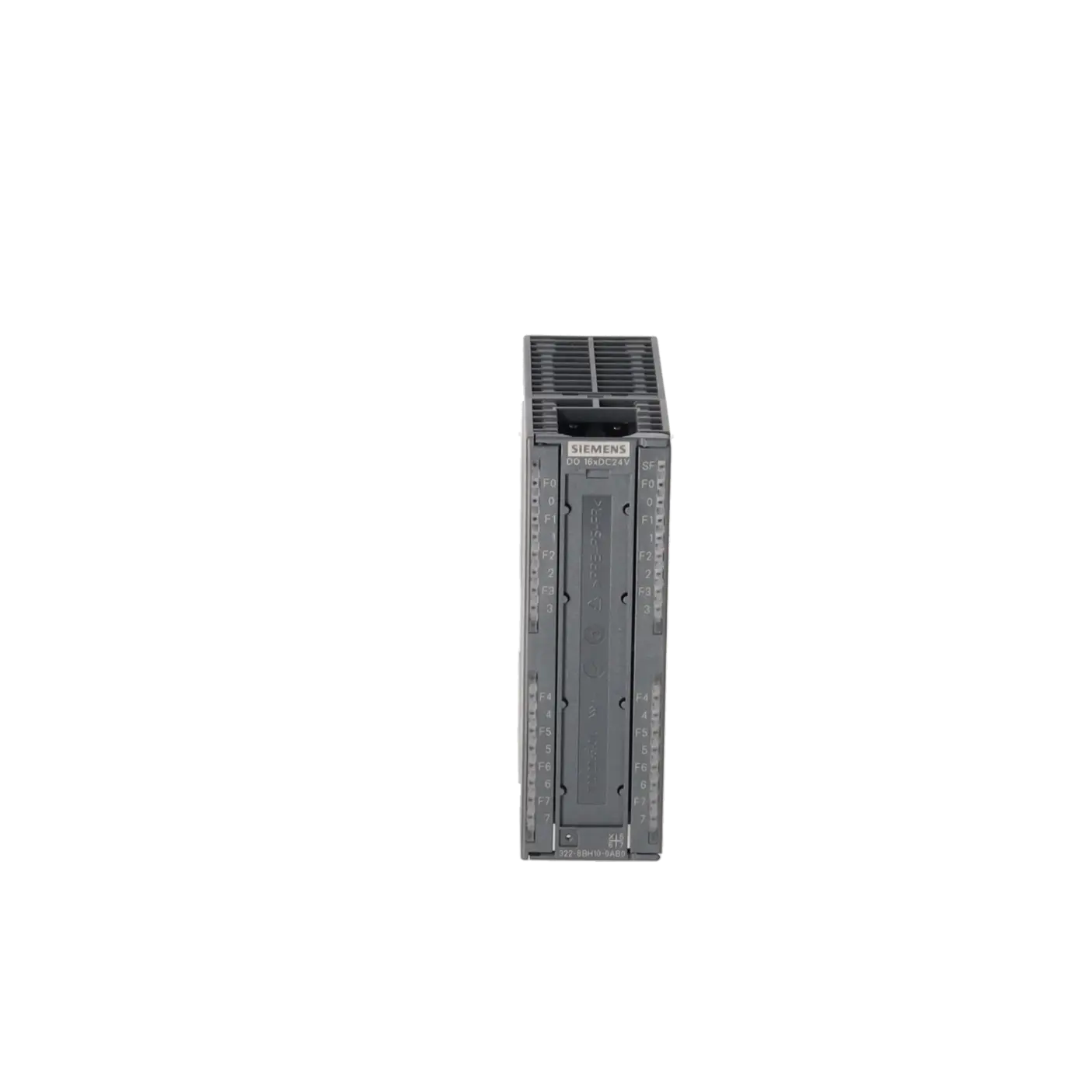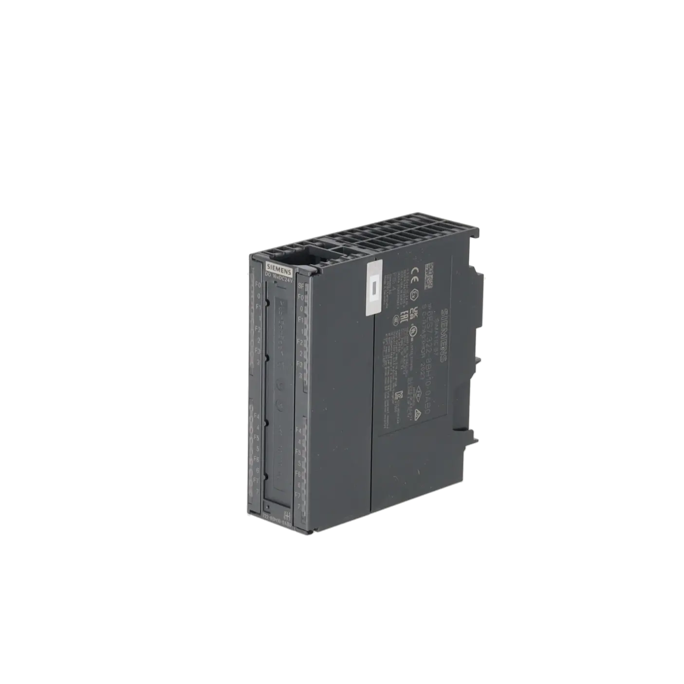


SIEMENS 6ES7322-8BH10-0AB0
-
SIEMENS | PLC Controls | Digital Input / Output Modules
- EICHLER-art.no.: K0252219
- EAN: 040892782745
- UPC: 040892782745
Product description
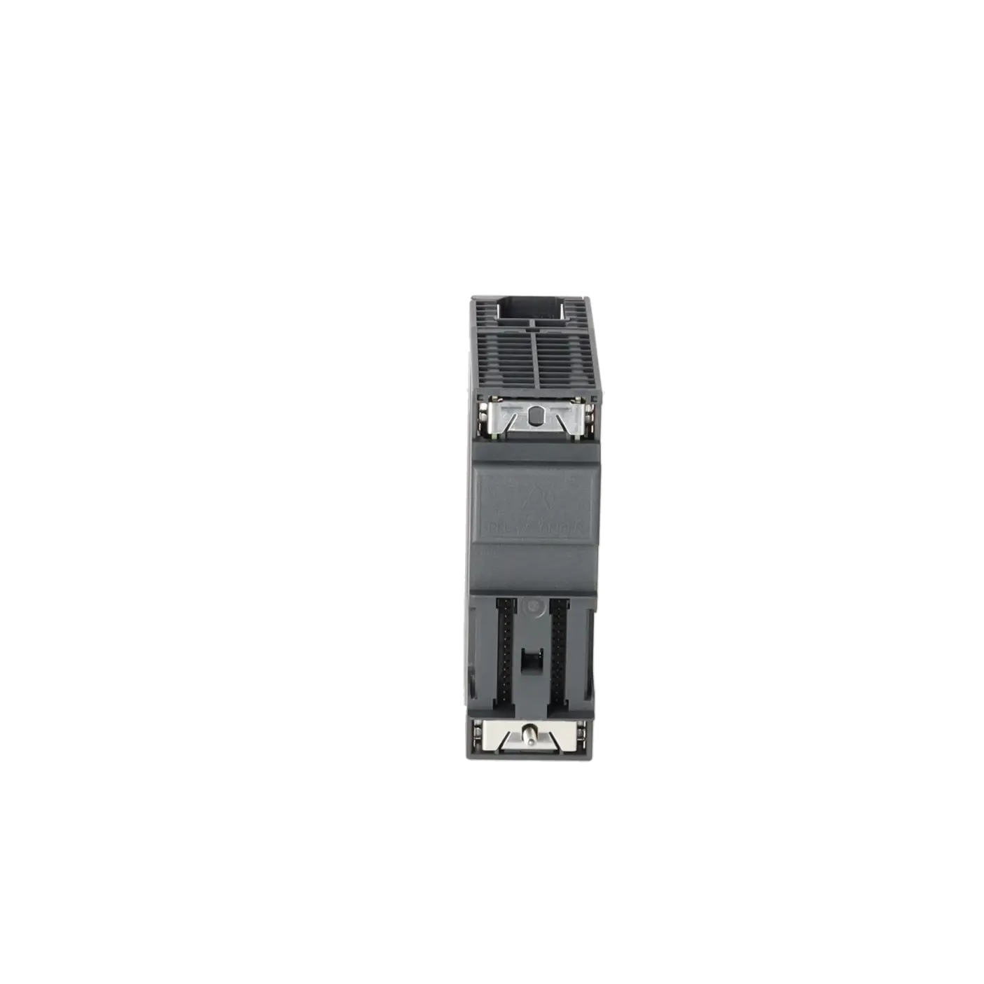
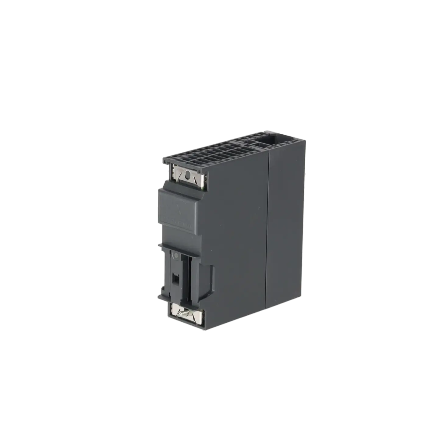
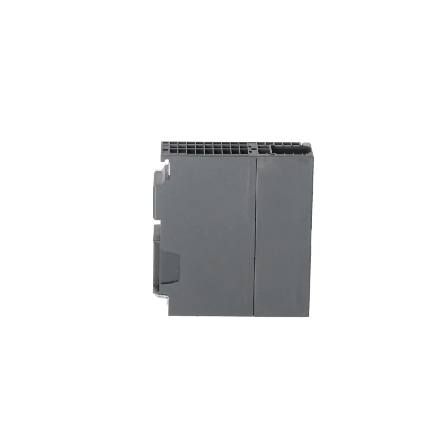
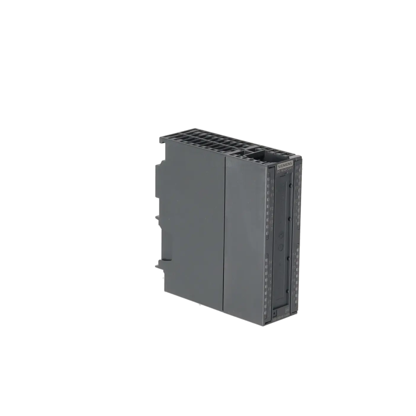
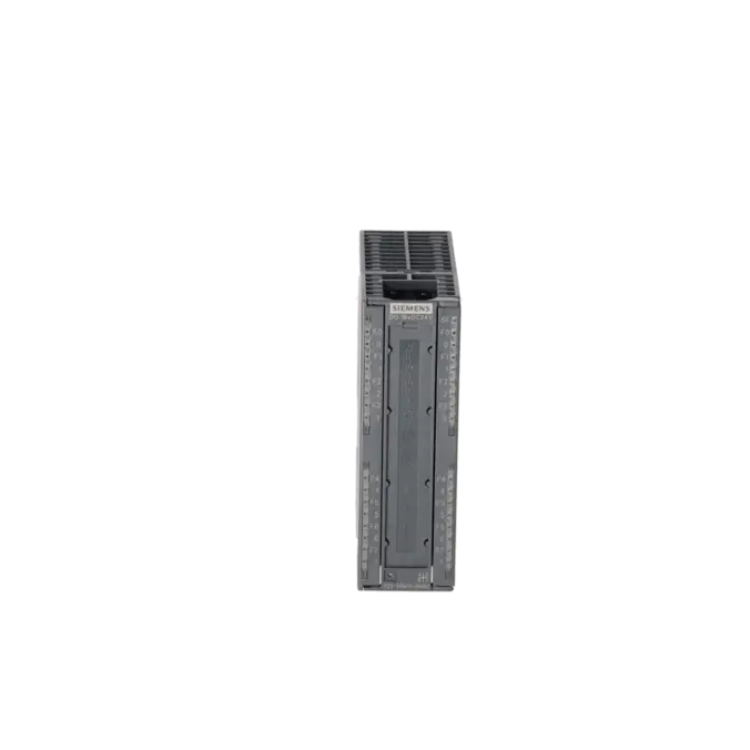
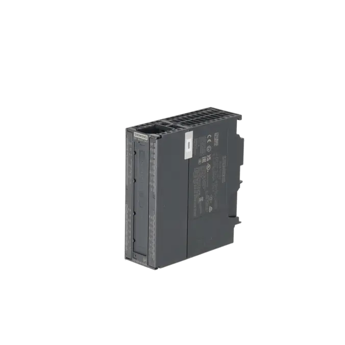
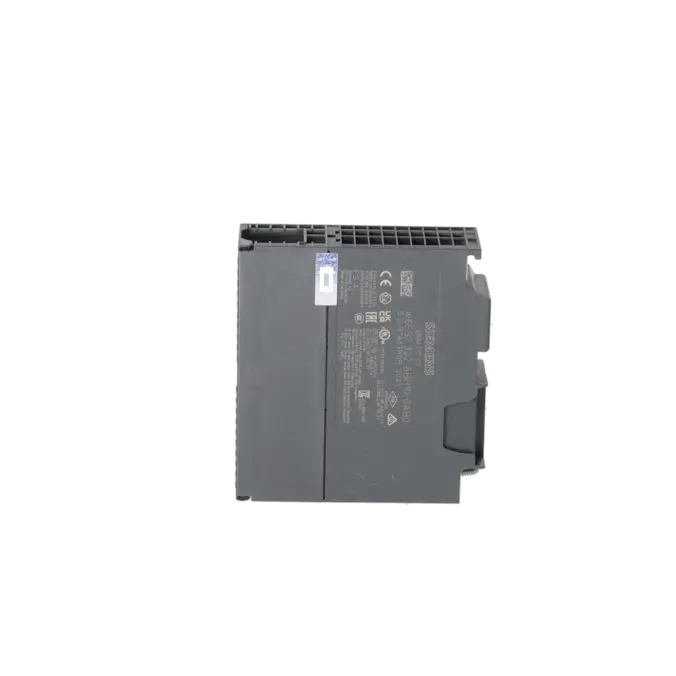
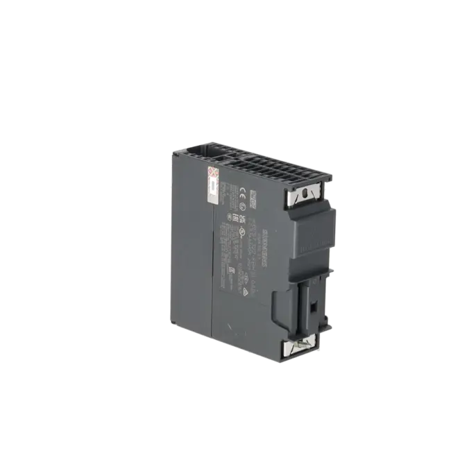
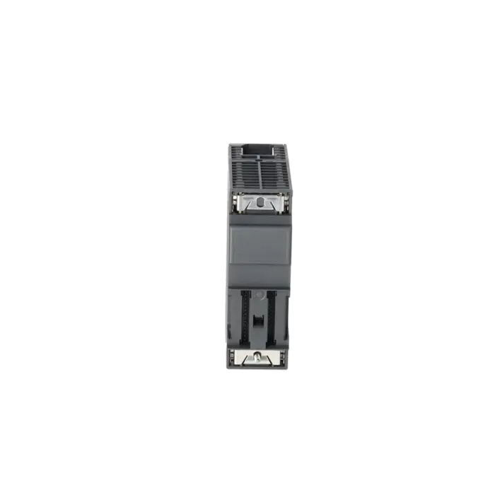
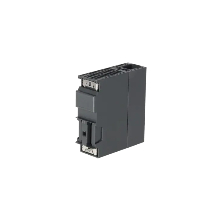
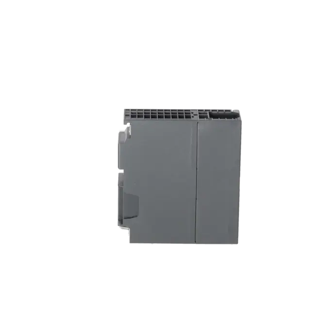
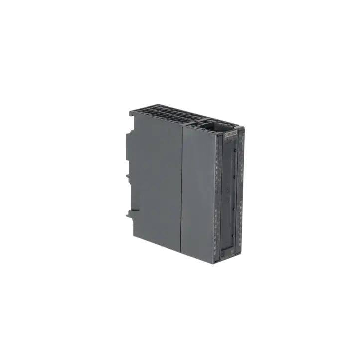
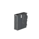
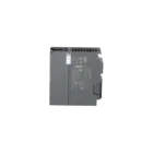
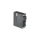
SIMATIC S7/PCS7, DIGITAL OUTPUT SM 322, 16 DO; 24 V DC / 0.5 A, DIAGNOSTICS-CAPABLE, WIRE BREAK DETECTION WITH 0 AND 1 SIGNAL, 1 X 40-POLE, INTERFACE IM 153-X HF REQUIRED
Services for SIEMENS 6ES7322-8BH10-0AB0
Repair
from 870,57 €
to 1.280,25 €
Replacement
Used
New
1.707,00 €
1.280,25 €
SIEMENS |
6ES7322-8BH10-0AB0 –
additional product information
| Delivery information | |||
|---|---|---|---|
| Export identifier | AL: N ECCN: EAR99H | ||
| Net weight | 0.33 | ||
| Quantity | 1 Stück | ||
| Packaging quantity | 1 | ||
| Additional product information | |||
|---|---|---|---|
| Product status | EOP: 2025-10-01 | ||
| EAN | 040892782745 | ||
| UPC | 040892782745 | ||
| Static lot number | 85389091 | ||
| List indicator | STPCS7 | ||
| Product group | 4428 | ||
| Country of origin | DE | ||
| Compliance with the substance restrictions according to RoHS directive | Since: 20110304 | ||
| Product classifications | Version | Classification | |
|---|---|---|---|
| eClass | 4 | / | |
| eClass | 5.1 | 27-24-22-04 | |
| eClass | 6.0 | 27-24-22-04 | |
| ETIM | 3 | / | |
| ETIM | 4 | EC001419 | |
| ETIM | 5 | EC001419 | |
What is the 6ES7322-8BH10-0AB0 and where is it used?
The 6ES7322-8BH10-0AB0 is a SIMATIC S7 / PCS 7 SM 322 digital output module from Siemens. It provides 16 digital 24 V DC outputs with 0.5 A per channel and is designed for applications where actuators such as solenoid valves, DC contactors or signal lamps must be switched reliably and monitored diagnostically. The module can be used centrally in S7-300 systems. For distributed operation in ET 200M, a compatible IM 153 interface module is required. This makes the module particularly relevant in existing process and factory automation systems where rapid fault localisation, short downtimes and a reliable spare-parts strategy are essential.
Overview of the most important technical data and what it means
The module operates with a 24 V DC load voltage within a permissible range of 20.4 to 28.8 V DC. Each of the 16 outputs provides a nominal current of 0.5 A, with a permissible range of 5 mA to 0.6 A per channel. For practical applications, it is important to note that the outputs are galvanically isolated in groups of four, the maximum load per group is 2 A, and the electronic short-circuit protection typically trips at 1.4 A. Diagnostic functions include wire-break detection, short-circuit monitoring and load-voltage monitoring. A 40-pin front connector is required. Cable lengths of up to 600 m unshielded and 1,000 m shielded make the module suitable for use in large-scale systems. These specifications are particularly important for maintenance and procurement because they determine wiring requirements, load selection and interchangeability.
Product status, life-cycle status and obsolescence
For the 6ES7322-8BH10-0AB0, Siemens specifies the lifecycle status PM400 – Announcement of Product Phase-Out, effective from 01 October 2023. The EICHLER product page additionally lists EOP (End of Product): 01 October 2025. Siemens also classifies the module as a spare part. For operators of older S7-300 and ET 200M installations, this increases the risk of longer procurement times and unplanned downtime. A universal 1:1 drop-in replacement is not specified on the product page. However, for planned migrations from ET 200M to ET 200SP HA, Siemens identifies the 6DL1132-6BH00-0PH1 module as a migration target in combination with a suitable I/O adapter. In practice, this means that repair, exchange and strategic stockholding remain important short-term measures, while retrofit and migration projects represent the long-term strategy.
Available EICHLER services and when they are relevant
For this module, EICHLER offers repair services with a typical turnaround time of 2–5 days. These services include technical cleaning, preventive maintenance, comprehensive functional testing and a minimum 24-month warranty. This is particularly relevant when an existing installation must be returned to operation quickly without modifying the project configuration. In addition, exchange units and used modules are available on request. These options are useful when unexpected failures must be addressed immediately or when critical spare-parts inventories need to be supplemented. New units are also available, currently with a stated delivery time of 1–3 days and available stock. For purchasing, maintenance and production teams, this provides a practical way to maintain operational reliability during the obsolescence phase and effectively reduce downtime costs.
| Attribute | Value |
|---|---|
| Supply voltage | |
| Load voltage L+ | |
| ● Rated value (DC) | 24 V |
| ● permissible range, lower limit (DC) | 20.4 V |
| ● permissible range, upper limit (DC) | 28.8 V |
| Input current | |
| from load voltage L+ (without load), max. | 100 mA |
| from backplane bus 5 V DC, max. | 100 mA |
| Power loss | |
| Power loss, typ. | 6 W |
| Digital outputs | |
| Number of digital outputs | 16 |
| Short-circuit protection | Yes |
| ● Response threshold, typ. | 1.4 A; per channel |
| Limitation of inductive shutdown voltage to | L+ (-68 V) |
| Switching capacity of the outputs | |
| ● on lamp load, max. | 5 W |
| Load resistance range | |
| ● lower limit | 48 Ω |
| ● upper limit | 4 kΩ |
| Output voltage | |
| ● for signal "1", min. | L+ (-0.7 V) |
| Output current | |
| ● for signal "1" rated value | 0.5 A |
| ● for signal "1" permissible range, min. | 5 mA |
| ● for signal "1" permissible range, max. | 0.6 A |
| ● for signal "0" residual current, max. | 0.7 mA |
| Output delay with resistive load | |
| ● "0" to "1", max. | 3 ms |
| ● "1" to "0", max. | 3 ms |
| Parallel switching of two outputs | |
| ● for uprating | No |
| ● for redundant control of a load | Yes |
| Switching frequency | |
| ● with resistive load, max. | 100 Hz |
| ● with inductive load (acc. to IEC 60947-5-1, DC13), max. | 2 Hz |
| ● on lamp load, max. | 10 Hz |
| Total current of the outputs (per group) | |
| horizontal installation | |
| — up to 60 °C, max. | 2 A |
| vertical installation | |
| — up to 40 °C, max. | 2 A |
| Cable length | |
| ● shielded, max. | 1 000 m |
| ● unshielded, max. | 600 m |
| Interrupts/diagnostics/status information | |
| Alarms | Yes |
| Diagnostics function | Yes |
| Alarms | |
| ● Diagnostic alarm | Yes |
| Diagnoses | |
| ● Diagnostic information readable | Yes |
| ● Wire break | Yes |
| ● Short-circuit | Yes |
| ● Missing load voltage | Yes |
| Diagnostics indication LED | |
| ● Rated load voltage PWR (green) | No |
| ● Group error SF (red) | Yes |
| ● Status indicator digital output (green) | Yes |
| ● Channel fault indicator F (red) | Yes |
| Potential separation | |
| Potential separation digital outputs | |
| ● between the channels | No |
| ● between the channels, in groups of | 4 |
| ● between the channels and backplane bus | Yes |
| ● between the channels and the power supply of the electronics | No |
| Isolation | |
| Isolation tested with | 500 V DC |
| Connection method | |
| required front connector | 1x 40-pin |
| Dimensions | |
| Width | 40 mm |
| Height | 125 mm |
| Depth | 120 mm |
| Weights | |
| Weight, approx. | 350 g |
| Fault description | Possible solution |
|---|---|
| Why does my 6ES7322-8BH10-0AB0 report a wire break even though the actuator is connected? | The module detects a wire break when the channel current falls below 1 mA. First check the wiring, terminal connections and the load between the module and the actuator. Unwired outputs or loads greater than 1 MΩ can also be detected as a wire break. If a channel is intentionally left open or a very high-resistance load is connected, the wire-break diagnostic settings for that channel should be checked in STEP 7 and disabled if necessary. |
| Why does the SM 322 report a short circuit to M? | This diagnostic message occurs when the output signal is ON and an overload or short circuit to M (0 V) exists on the channel. Disconnect the load, inspect the wiring for damaged insulation or incorrect bridging, and measure the actuator current consumption. The module features electronic short-circuit protection; the trip threshold is typically 1.4 A, while the nominal channel current is 0.5 A. The channel should only be tested again after the overload or wiring fault has been eliminated. |
| Why does the 6ES7322-8BH10-0AB0 report a short circuit to L+? | Siemens defines this fault as a short circuit between the output and the L+ supply voltage. Check the terminal assignment, crossed conductors, crushed cables and unintended bridges on the front connector. Also verify that the load voltage is within the permitted range of 20.4 to 28.8 V DC. As long as the short circuit to the supply remains present, reliable operation of the affected output channels cannot be guaranteed. |
| Why does the module report a missing L+ load voltage? | This diagnostic message is generated on a channel-group basis. If a load voltage fails, the module reports the fault for all four channels within the affected group. In addition, load-voltage monitoring remains active even if channel diagnostics for this function have been disabled. Check the 24 V supply at L+, the channel group assignment, the power supply unit, wiring and terminal connections. Voltage drops below 20.4 V DC are particularly likely to cause switching problems and diagnostic alarms. |
| Why does a “Fuse defect” or discrepancy fault appear even though the wiring seems correct? | When discrepancy monitoring is enabled, the module continuously compares the commanded output state with the actual output state. If a deviation is detected, the affected channel group is switched off and the fault is reported as “Fuse defect”. Check whether discrepancy diagnostics have been intentionally enabled in STEP 7 and whether an internal channel or output stage is no longer switching correctly. After removing and reinserting the module or after a restart, the outputs are re-enabled and the monitoring process starts again. |
Is the 6ES7322-8BH10-0AB0 still available or only relevant as a spare part?
Siemens classifies the module with the lifecycle status PM400 and identifies it as a spare part. At the same time, EICHLER continues to offer several procurement options for this module, including new units, repairs, exchange units and used units. As of 2 June 2026, the EICHLER product page listed new units with a delivery time of 1–3 days and available stock, while repairs were quoted with a turnaround time of 2–5 days. For operators, this means that the module is no longer a future-oriented product but remains available and serviceable.
Can I use the 6ES7322-8BH10-0AB0 in both a central S7-300 system and an ET 200M station?
Yes. Siemens specifies that the module can be used centrally in S7-300 systems with all supported CPUs. For distributed operation in ET 200M, Siemens lists compatible IM 153 interface modules, including IM 153-2 and IM 153-4 in the specified hardware versions. Siemens also specifies STEP 7 V5.5 (HSP0217) or later as a requirement. This is important for maintenance engineers because it allows a quick check of whether the existing station and engineering environment are compatible before replacing the module.
Which front connector is required for the 6ES7322-8BH10-0AB0?
The module requires a 40-pin front connector. Siemens offers suitable versions with both screw terminals and spring-loaded terminals. The 40-pin front connectors listed in the Siemens documentation include 6ES7392-1AM00-0AA0 and 6ES7392-1BM01-0AA0. This is important during procurement because, in many replacement projects, not only the module itself but also the connection method and condition of the front connector influence the overall restart time.
Can I replace a 6ES7322-8BH0x-0AB0 with a 6ES7322-8BH10-0AB0 without changing the project?
Yes. Siemens states that a 6ES7322-8BH0x-0AB0 can be replaced by a 6ES7322-8BH10-0AB0 without modifying the existing configuration. However, there is one important limitation: discrepancy monitoring is not available in this replacement scenario. Older STEP 7 versions may also have restrictions relating to substitute values and parameter assignment. For maintenance teams, this is a significant advantage because it allows rapid replacement in existing installations without immediately requiring project modifications.
Is there a successor to the 6ES7322-8BH10-0AB0?
Siemens does not identify a general 1:1 successor for this module on the product page. However, for migrations from ET 200M to ET 200SP HA, Siemens maps the 6ES7322-8BH10-0AB0 to the 6DL1132-6BH00-0PH1 module. This migration is not a simple plug-in replacement and requires an appropriate I/O adapter. In practice, this means that operators looking for short-term system stability will often benefit more from repair or exchange, whereas those aiming to improve long-term availability should evaluate a retrofit strategy.
When is repair more sensible than exchange or retrofit?
Repair is usually the best option when the existing installation is expected to continue operating unchanged and downtime costs are high. EICHLER specifies a repair turnaround time of 2–5 days for this module, including technical cleaning, preventive maintenance, functional testing and a minimum 24-month warranty. Exchange units or used modules are preferable when immediate replacement is more important than recovering the original unit. Retrofit solutions become attractive when obsolescence, spare-parts risk and modernisation requirements are being addressed together as part of a long-term strategy.