


SIEMENS 6ES7322-5SD00-0AB0
-
SIEMENS | PLC Controls | Digital Input / Output Modules
- EICHLER-art.no.: K0118558
- EAN: 4025515061083
- UPC: 662643230284
Product description
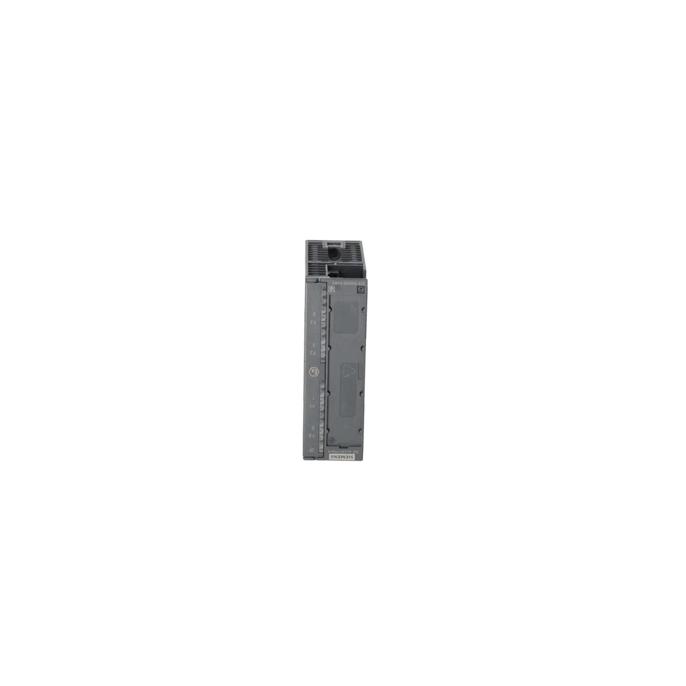
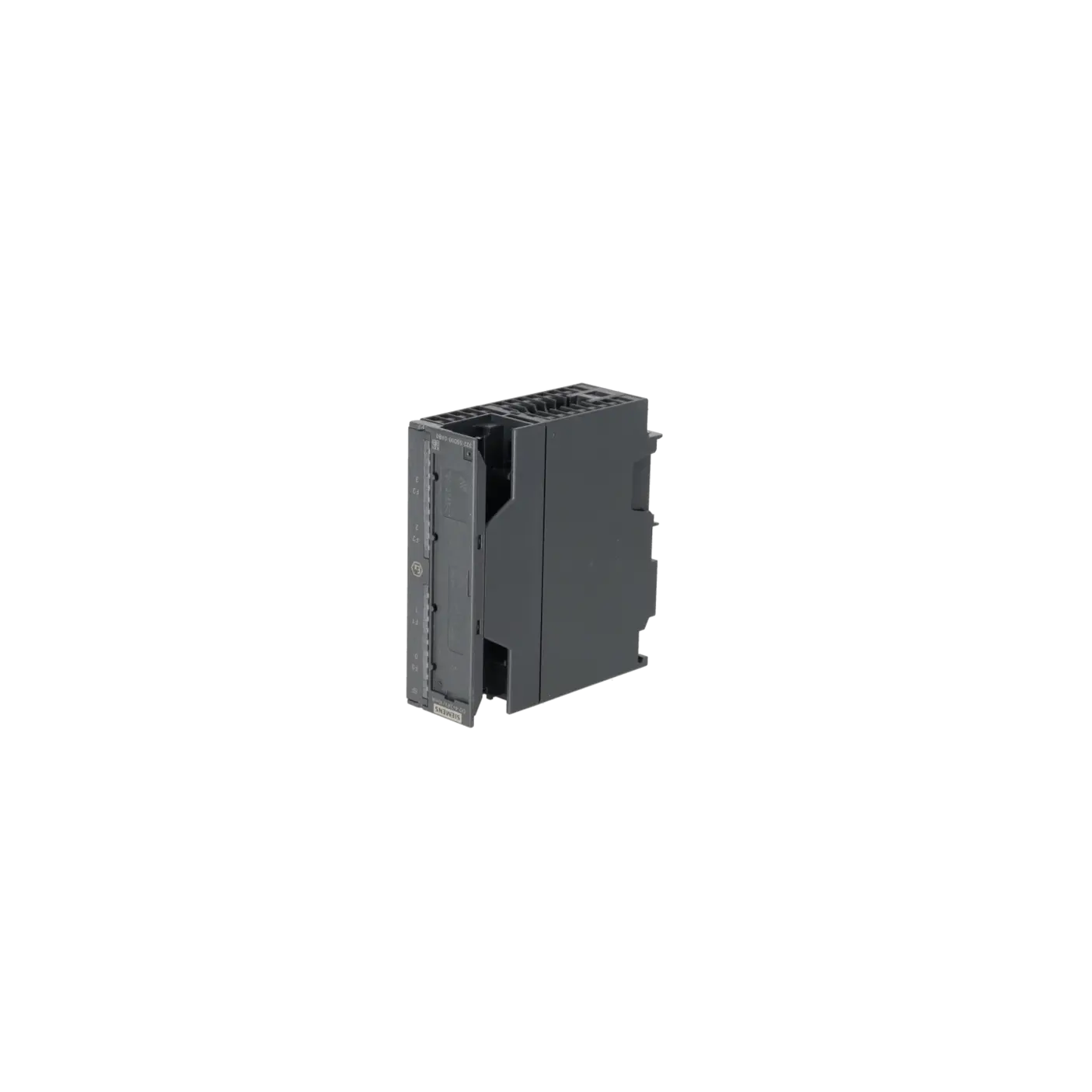
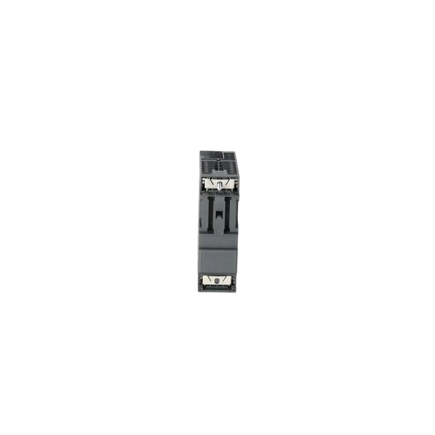
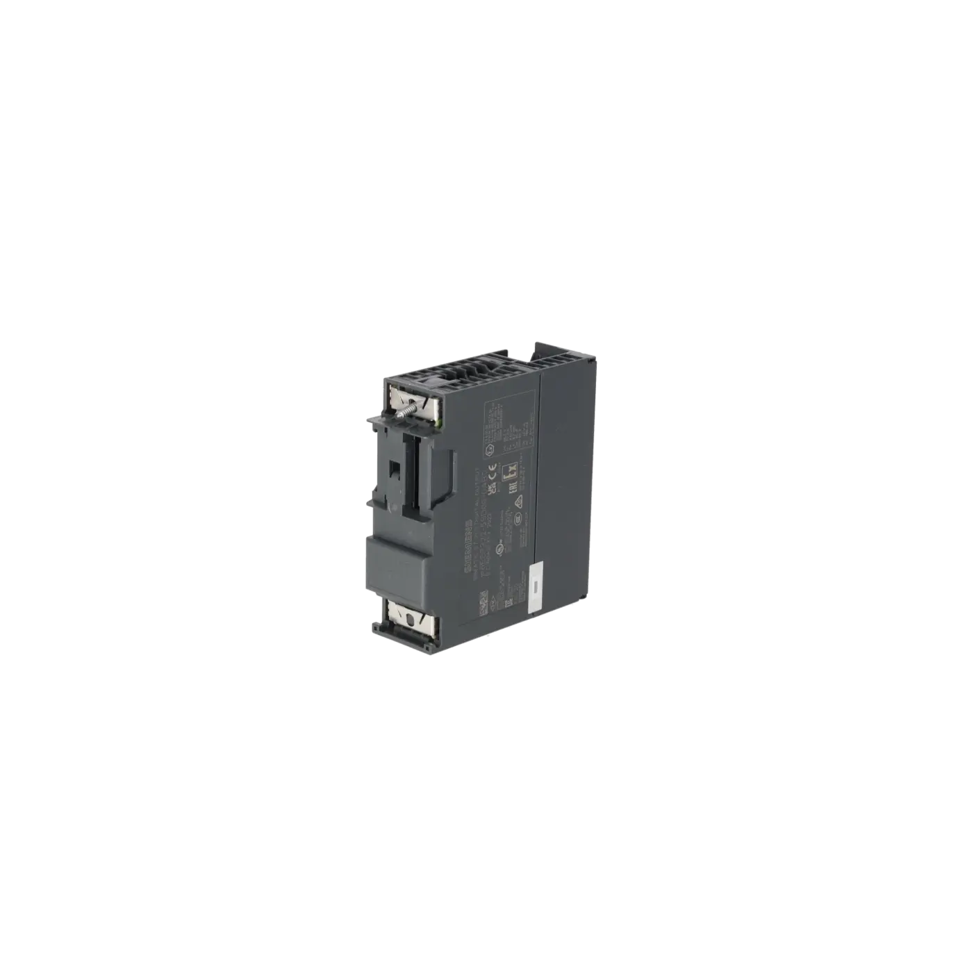
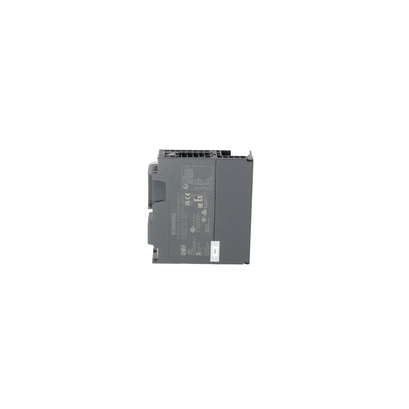
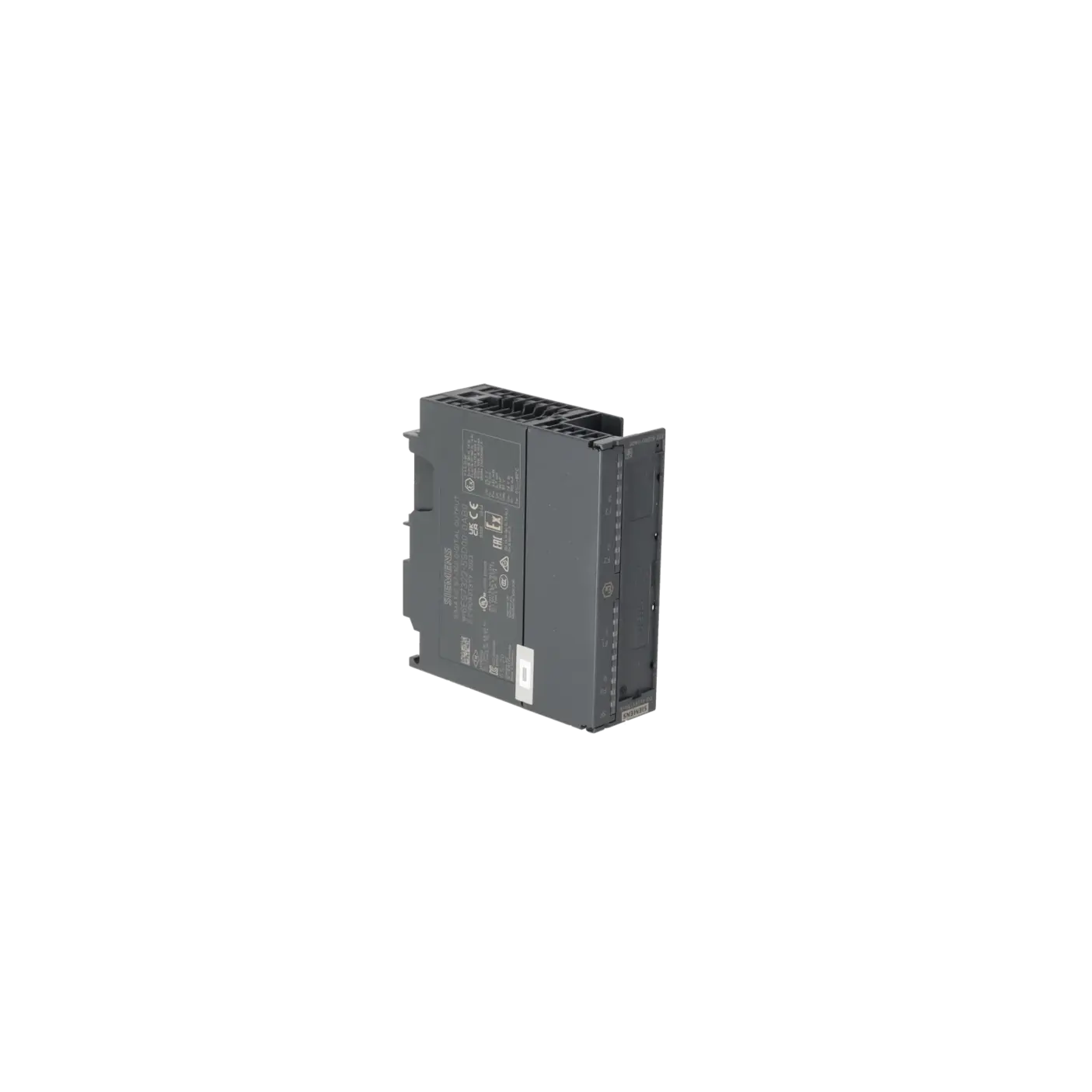
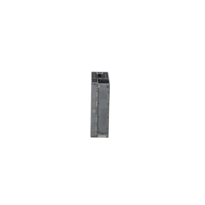
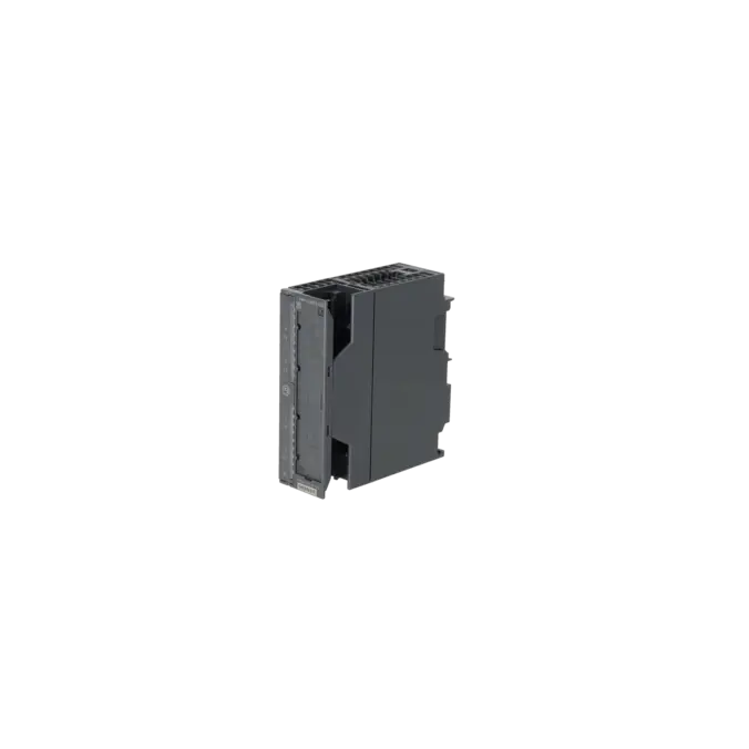
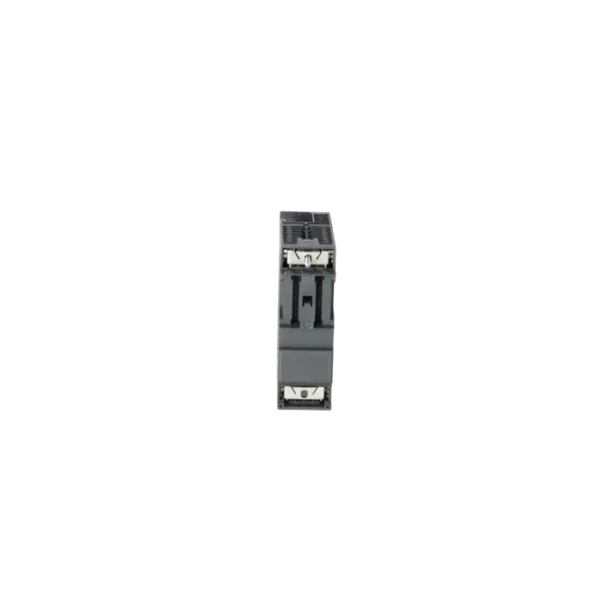
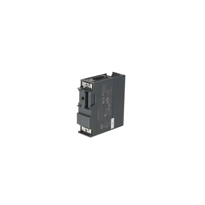
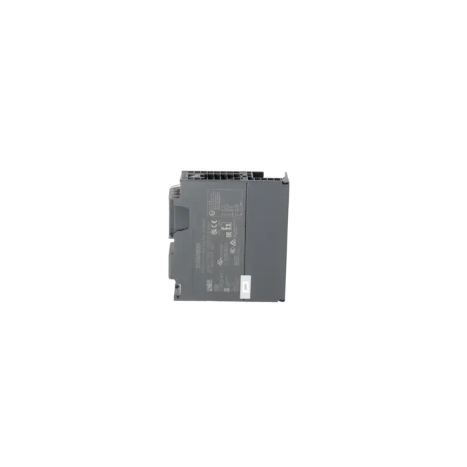
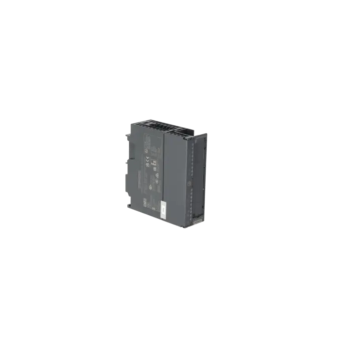
SIMATIC S7, DIGITAL OUTPUT SM 322, ISOLATED, 4 DO, 24 V DC, 10 MA, 1 X 20-POLE, FOR SIGNALS FROM THE HAZARDOUS AREA, DIAGNOSTICS-CAPABLE, PTB TESTED
Services for SIEMENS 6ES7322-5SD00-0AB0
SIEMENS |
6ES7322-5SD00-0AB0 –
additional product information
| Delivery information | |||
|---|---|---|---|
| Export identifier | AL: N ECCN: EAR99H | ||
| Net weight | 0.4 | ||
| Quantity | 1 Stück | ||
| Packaging quantity | 1 | ||
| Additional product information | |||
|---|---|---|---|
| Product status | EOP: 2025-10-01 | ||
| EAN | 4025515061083 | ||
| UPC | 662643230284 | ||
| Static lot number | 85389091 | ||
| List indicator | STPCS7 | ||
| Product group | 4428 | ||
| Country of origin | DE | ||
| Compliance with the substance restrictions according to RoHS directive | Since: 20150303 | ||
| Product classifications | Version | Classification | |
|---|---|---|---|
| eClass | 4 | 27-24-03-04 | |
| eClass | 5.1 | 27-24-22-04 | |
| eClass | 6.0 | 27-24-22-04 | |
| ETIM | 3 | / | |
| ETIM | 4 | EC001419 | |
| ETIM | 5 | EC001419 | |
What is the 6ES7322-5SD00-0AB0 and where is it used?
The 6ES7322-5SD00-0AB0 is a SIEMENS SIMATIC S7-300 SM 322 digital output module with 4 digital outputs, 24 V DC, 10 mA, and 1 x 20-pin front connector. The module is electrically isolated, diagnostics-capable, and designed for signals from hazardous (Ex) areas. Siemens describes it as a module for intrinsically safe valves, audible alarms, and indicator devices. This makes it particularly suitable for applications where field signals from potentially explosive environments must be switched and monitored safely. Typical areas of use include process plants, chemical facilities, energy systems, process engineering lines, and decentralised ET 200M architectures where proven S7-300 technology is to be maintained or serviced over the long term.
Overview of the key technical data and what it means
The key specifications clearly indicate the intended application of the module: 4 outputs, 24 V DC load voltage, maximum 10 mA per output, electronic short-circuit protection, diagnostic functionality, a switching frequency of up to 100 Hz, and a maximum unshielded cable length of 200 m. For maintenance personnel, it is important to note that the module provides channel-specific fault indicators F0 to F3 as well as a group fault indicator (SF). For hazardous-area applications, the [EEx ib] IIC rating, PTB certification, and intrinsic safety values such as Uo 25.2 V, Io 70 mA, and Po 440 mW are particularly relevant. For purchasing and engineering teams, these specifications show that the module is not a universal-purpose output module, but rather a specialised Ex output module intended for defined, low-load actuators and signalling circuits.
Product status, life-cycle status and obsolescence
From a life-cycle perspective, the 6ES7322-5SD00-0AB0 is now clearly a legacy and spare-part product. Siemens lists the module as a spare part, and the EICHLER product page specifies a product status of EOP: 01 October 2025. For operators, this means that the module remains technically important in many existing installations, but the procurement risk increases as stock levels become more limited and projects continue to require identical replacement parts. For purchasing and production departments, availability, replacement options, repair capability and stockholding strategies therefore become more important than new project planning. The Siemens product information reviewed does not identify a verified compatible successor for this specific order number. As a result, a structured spare-parts and service strategy becomes increasingly important.
EICHLER services for the 6ES7322-5SD00-0AB0
For companies seeking to minimise downtime or manage obsolescence risks, the services offered by EICHLER are tailored to a range of practical scenarios. Repair is particularly suitable when an existing module exhibits intermittent diagnostic faults, sporadic failures, or load-dependent channel issues, while the installation still requires the exact same part number. EICHLER specifies a turnaround time of 2 to 5 days and describes the service as including technical cleaning, preventive maintenance, comprehensive functional testing, and a minimum 24-month warranty. Exchange, used, and new units are available when a rapid replacement is required. For new units, EICHLER currently indicates a delivery time of 1 to 3 days. These options help maintenance teams, purchasing departments and decision-makers maintain operational reliability in a cost-effective manner, even during the later stages of the product life cycle.
| Attribute | Value |
|---|---|
| Supply voltage | |
| Load voltage L+ | |
| ● Rated value (DC) | 24 V |
| ● Reverse polarity protection | Yes |
| Input current | |
| from load voltage L+ (without load), max. | 160 mA |
| from backplane bus 5 V DC, max. | 85 mA |
| Power loss | |
| Power loss, typ. | 3 W |
| Digital outputs | |
| Number of digital outputs | 4 |
| Short-circuit protection | Yes; Electronic |
| ● Response threshold, typ. | Output current with short-circuit protection, min. 10 mA + 10 % |
| Load resistance range | |
| ● upper limit | 390 Ω; Two-wire connection |
| Output voltage | |
| ● Rated value (DC) | 24 V |
| Output current | |
| ● for signal "1" permissible range for 0 to 60 °C, max. | 10 mA; ±10 % |
| Switching frequency | |
| ● with resistive load, max. | 100 Hz |
| Cable length | |
| ● unshielded, max. | 200 m |
| Interrupts/diagnostics/status information | |
| Diagnostics function | Yes |
| Diagnoses | |
| ● Diagnostic information readable | Yes |
| ● Short-circuit | Yes |
| Diagnostics indication LED | |
| ● Group error SF (red) | Yes |
| ● Status indicator digital output (green) | Yes |
| ● Channel fault indicator F (red) | Yes |
| Ex(i) characteristics | |
| Module for Ex(i) protection | Yes |
| maximum values for connecting terminals for gas group IIC | |
| ● Uo (no-load voltage), max. | 25.2 V |
| ● Io (short-circuit current), max. | 70 mA |
| ● Po (power output), max. | 440 mW |
| ● Co (permissible external capacity), max. | 90 nF |
| ● Lo (permissible external inductivity), max. | 6.7 mH |
| Potential separation | |
| Potential separation digital outputs | |
| ● between the channels | Yes; 60 V DC/30 V AC when used in the hazardous area; 400 V DC/250 V AC when used in NON-hazardous area |
| ● between the channels, in groups of | 1 |
| ● between the channels and backplane bus | Yes; 60 V DC/30 V AC when used in the hazardous area; 400 V DC/250 V AC when used in NON-hazardous area |
| ● Between the channels and load voltage L+ | Yes; 60 V DC/30 V AC when used in the hazardous area; 400 V DC/250 V AC when used in NON-hazardous area |
| Standards, approvals, certificates | |
| Use in hazardous areas | |
| ● ATEX marking | [EEx ib] IIC |
| ● FM marking | AIS CL.1, DIV 1, GP A, B, C, D; CL.I, DIV 2, GP A, B, C, D T4 |
| ● Test number PTB | Ex-96.D.2093X |
| Ambient conditions | |
| Ambient temperature during operation | |
| ● max. | 60 °C |
| Connection method | |
| required front connector | 20-pin |
| Dimensions | |
| Width | 40 mm |
| Height | 125 mm |
| Depth | 120 mm |
| Weights | |
| Weight, approx. | 230 g |
| Fault description | Possible solution |
|---|---|
| Why does the 6ES7322-5SD00-0AB0 report a short circuit to M? | This diagnostic is only detected when the affected output is set to “1”. Typical causes are an output overload or a short circuit between two output lines. Check the connected actuator, the wiring through to the field device, and any possible short circuits to M. Once the fault has been corrected, the diagnostic should clear in STEP 7. If diagnostic alarms are enabled, an additional alarm may also be triggered at the CPU. |
| Why does the 6ES7322-5SD00-0AB0 report a wire break on a channel? | A wire break is only detected when the output is set to “1” and only if wire-break diagnostics have been enabled for that channel. Check the wiring between the module and the actuator for an open circuit. If the channel is intentionally unused and left open, the wire-break diagnostic for that channel should be disabled in the parameter settings to prevent a permanent fault indication. Wire-break detection is triggered at a current of ≤ 0.15 mA. |
| Why does the 6ES7322-5SD00-0AB0 report missing load voltage or missing auxiliary voltage? | This message occurs when an output is set to “1”, or module-wide, if the module’s L+ supply voltage is missing or if an internal channel supply has failed. First check the 24 V load voltage, the L+/M supply wiring, terminal connections, front connector and the power supply within the rack. If the diagnostic remains despite a correct supply voltage, the module should be considered faulty and either replaced or tested. |
| Why does the 6ES7322-5SD00-0AB0 report “Module not parameterised” or invalid parameters? | According to Siemens, this diagnostic occurs when the module has been supplied with invalid parameters via an SFC. Check the hardware configuration, download the valid parameter set again to the CPU or station, and verify that the correct order number is configured in the project. This is particularly important after module replacement, project migration or station modifications to ensure that channel diagnostics and substitute-value behaviour operate correctly. |
| Why do watchdog, EPROM, RAM or CPU errors occur on the 6ES7322-5SD00-0AB0? | Siemens states that these errors can be caused by temporary high electromagnetic interference or by a faulty module. Check shielding, grounding, cable routing and the stability of the power supply. Then power-cycle the CPU by switching the supply OFF and ON again. If the fault reappears, the module is highly likely to be defective and should be replaced or professionally tested. |
Is the 6ES7322-5SD00-0AB0 still available, or is it only obtainable as a spare part?
The order number can still be found on the market, but it clearly falls into the legacy support and spare-parts category. Siemens classifies the product as a spare part, and EICHLER lists an EOP (End of Product) date of 01 October 2025 for this specific order number. For purchasing departments, this means that availability is increasingly dependent on stock levels, service providers, repaired modules, and targeted stockholding strategies rather than on long-term availability for new projects. Companies aiming to minimise downtime should therefore consider not only purchasing replacement units, but also securing repair and exchange options.
Can the 6ES7322-5SD00-0AB0 be used in an ET 200M system?
Yes. Siemens documentation classifies the module as part of the S7-300 / ET 200M Ex I/O range. This is particularly important for operators wishing to continue using decentralised I/O systems based on an existing IM 153 architecture. At the same time, the Ex-specific installation requirements must be observed. If signal lines are routed into hazardous areas, the relevant Siemens guidelines for intrinsically safe installations must be followed. For modernisation projects, it is also worth noting that although the module is listed as suitable for redundant systems, Siemens specifies certain restrictions for redundant operation in hazardous-area applications.
What does “DO 4 x 24V/10mA” actually mean for this module?
The designation refers to four digital outputs operating at 24 V DC, with a maximum output current of 10 mA per channel. This is the key factor when evaluating the connected load. The module is designed for small, defined intrinsically safe loads and is not suitable for standard field devices requiring higher current levels. Siemens identifies intrinsically safe valves, audible alarms, and indicator devices as typical applications. When sourcing a replacement module, it is therefore important not only to compare the order number, but also to verify the load type, hazardous-area requirements, current consumption, and required diagnostic functions of the connected field device.
Which front connector is required for the 6ES7322-5SD00-0AB0?
The module requires a 20-pin front connector. This requirement is specified both in the additional product data on the EICHLER website and in Siemens product documentation. For service, stockholding and retrofit activities, this is important because a module replacement requires not only the correct electronics but also a mechanically and electrically compatible connector. Siemens offers suitable 20-pin front connectors for S7-300 signal modules within its accessories range. Having the correct connector available in advance helps ensure a smooth replacement process and avoids delays during downtime.
What happens to the outputs when the CPU enters STOP mode or when L+ is missing?
The output state depends on both the CPU operating mode and the availability of the L+ supply voltage. During RUN mode with L+ present, the module follows the output values provided by the CPU. If L+ is missing, the outputs switch to a 0 signal. In STOP mode, the module can either output a substitute value or retain the last valid value, depending on its parameterisation. According to Siemens, the default setting is a substitute value of 0 signal. For maintenance personnel, this information is important because it determines how connected actuators behave during power failures or CPU status changes.
Is there a verified manufacturer successor for the 6ES7322-5SD00-0AB0?
No verified, compatible manufacturer successor for this exact order number is identified in the Siemens and EICHLER sources reviewed. In practical terms, this means that operators of existing installations will usually need to choose between an original spare part, a tested used module, an exchange unit, or repair of the existing module. From an obsolescence-management perspective, this is a typical situation where identical part numbers, verified functionality, and reliable service channels are often more valuable than a theoretical migration path that could introduce additional engineering effort, validation requirements and operational risk in a live hazardous-area application.