SIEMENS 6ES7322-5HF00-0AB0
-
SIEMENS | PLC Controls | Digital Input / Output Modules
- EICHLER-art.no.: K0118556
- EAN: 4019169350662
- UPC: 040892561142
Product description
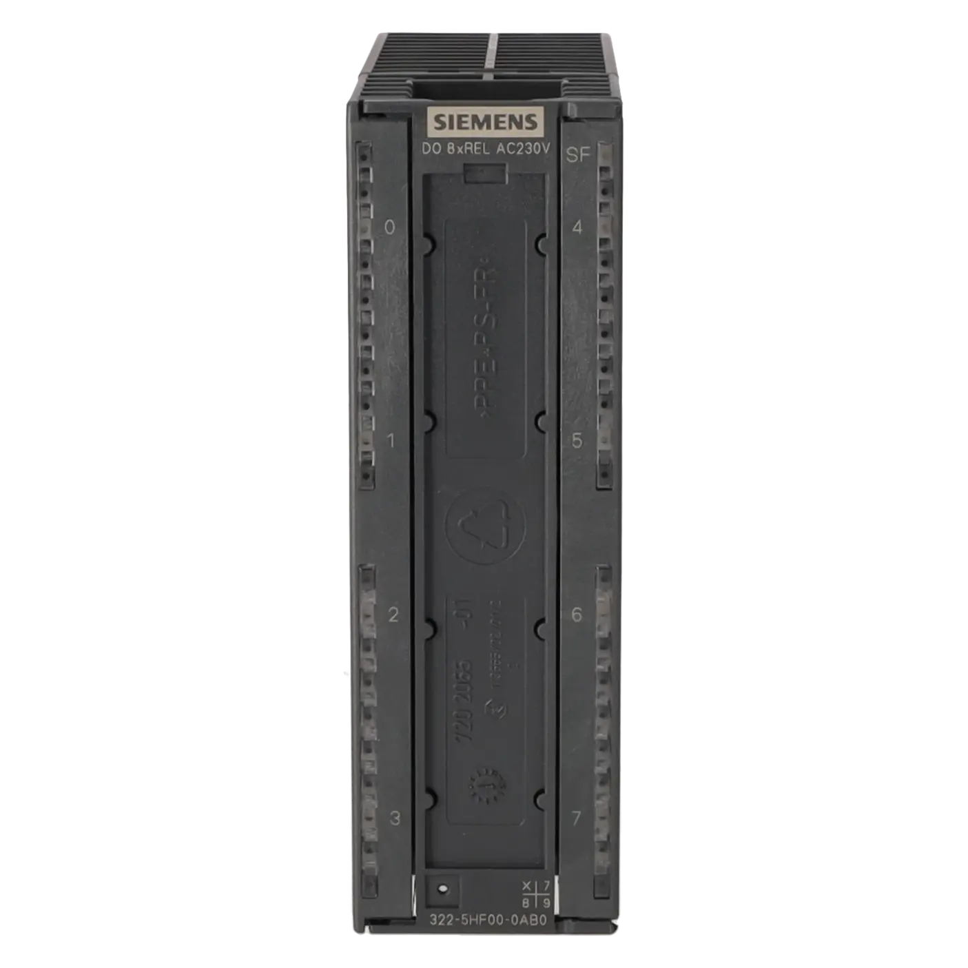
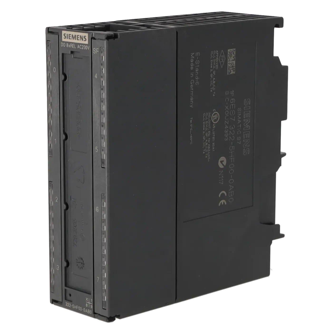
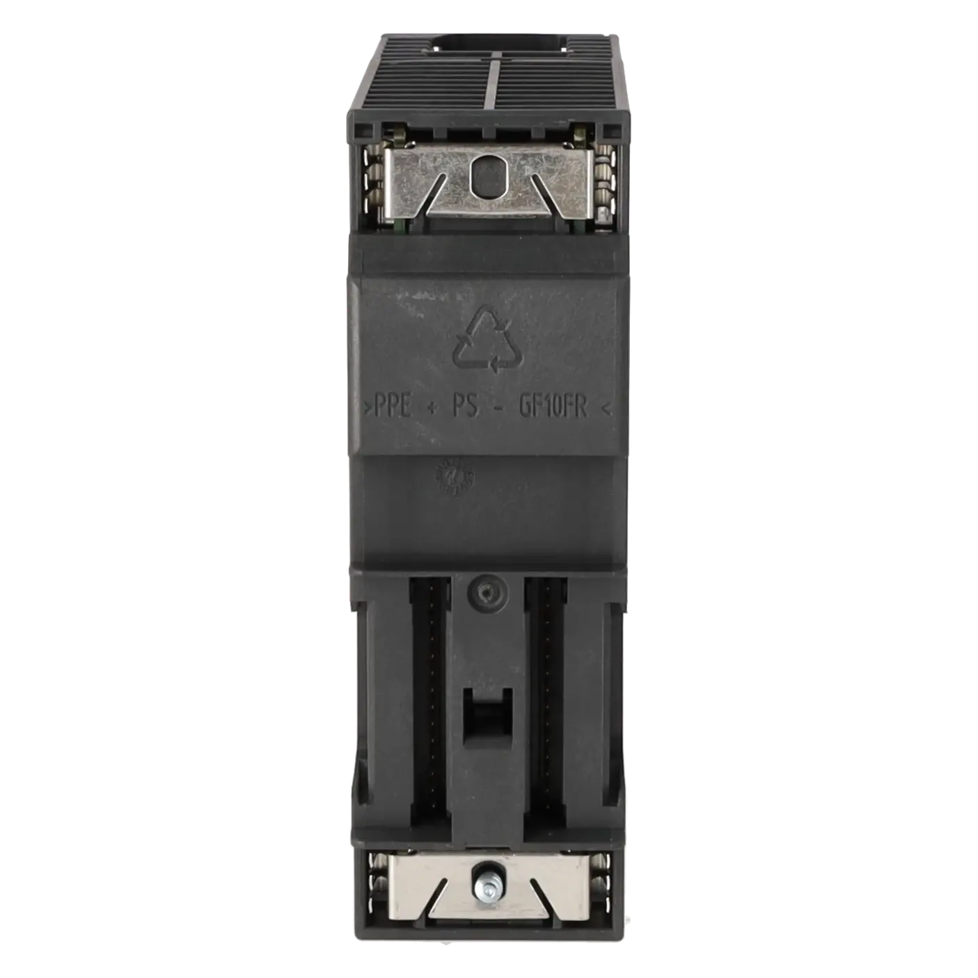
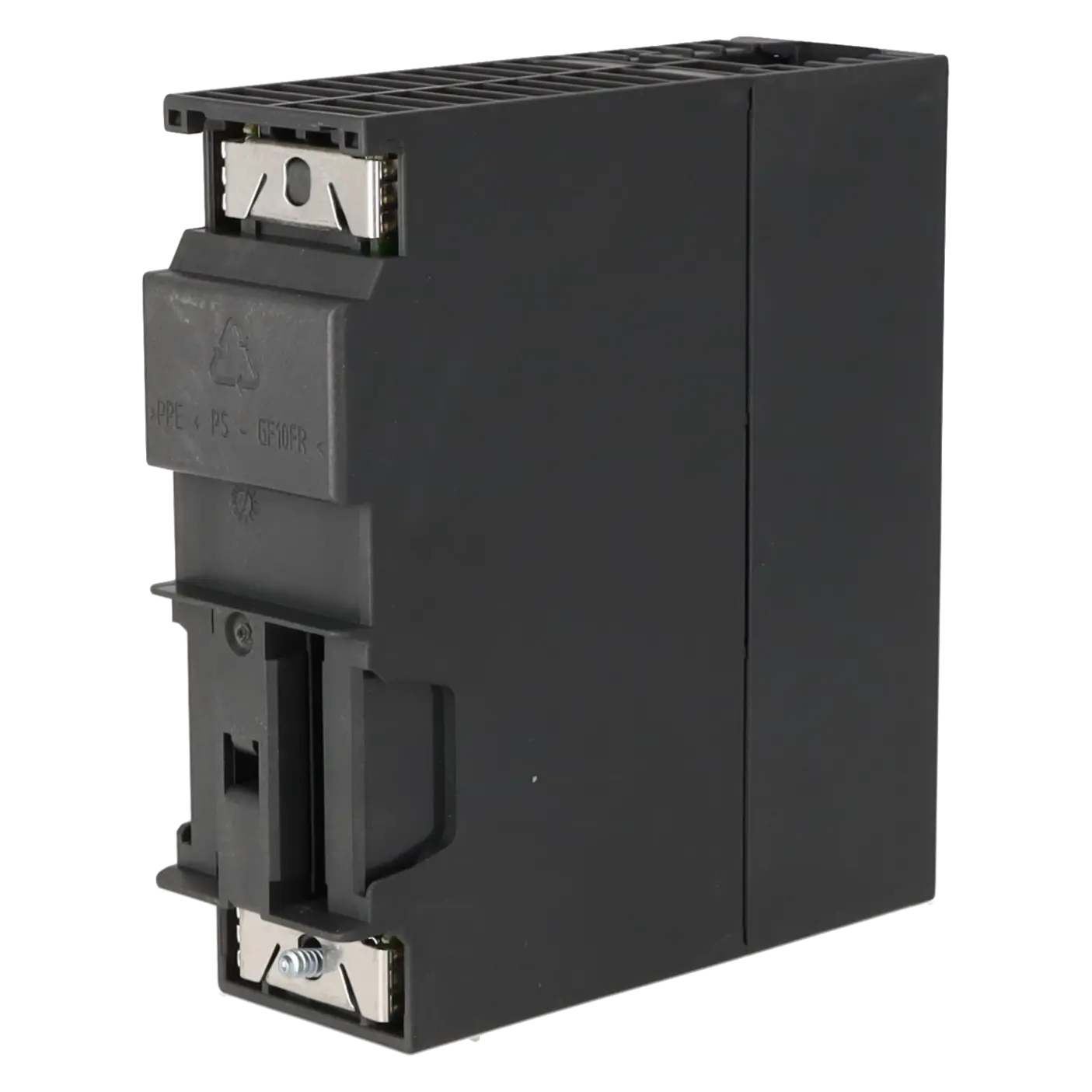
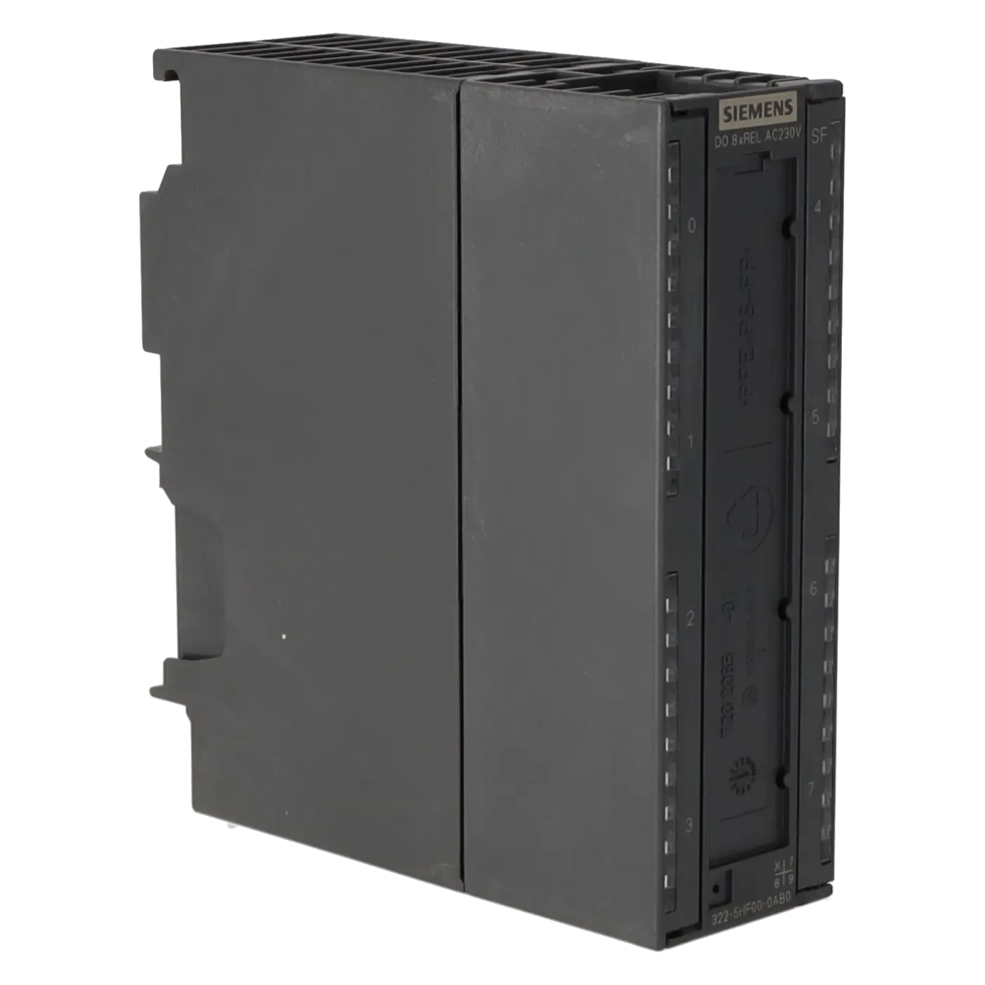
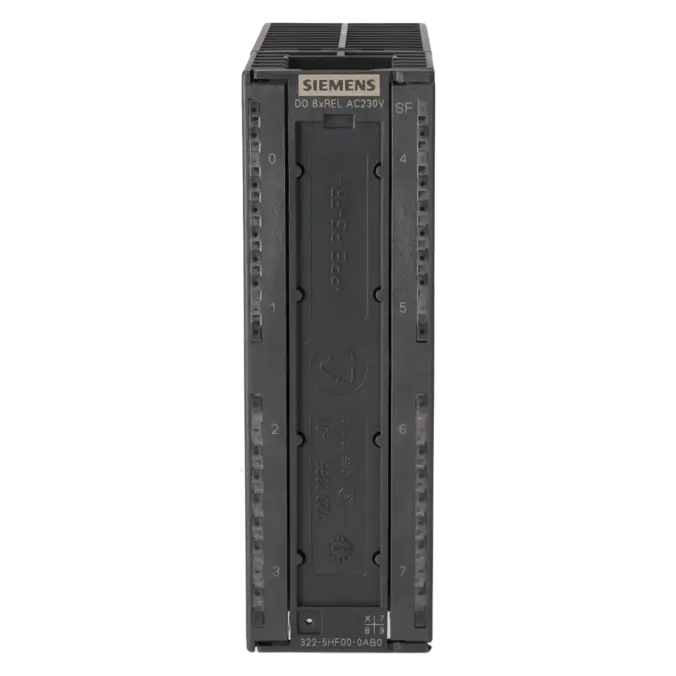
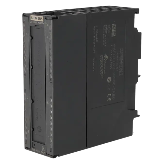
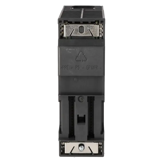
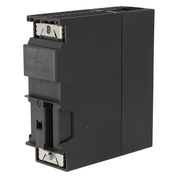
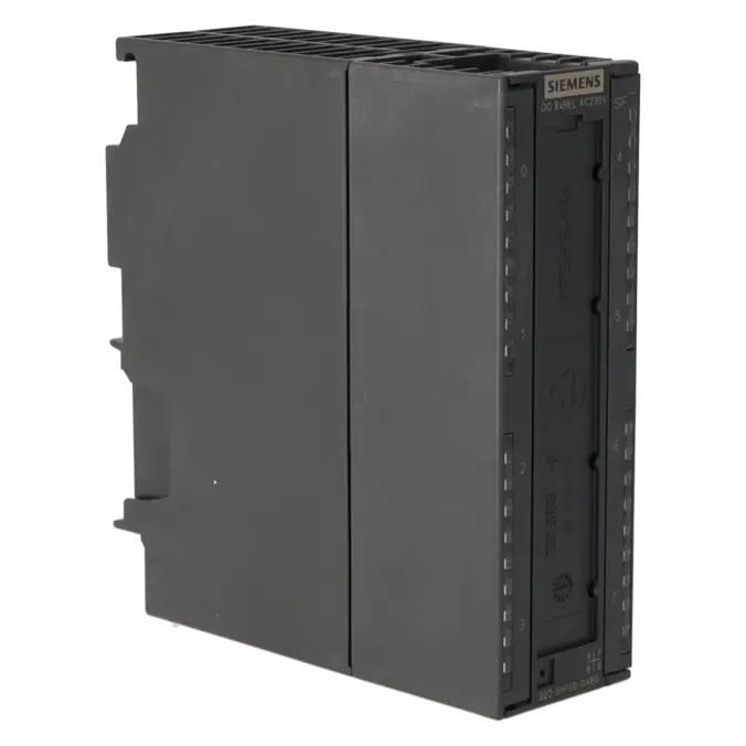
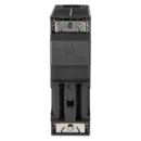
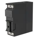
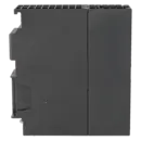
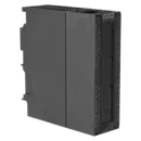
SIMATIC S7-300, DIGITAL OUTPUT SM 322, ISOLATED, 8 DO (RELAY), 1X 40-POLE, 24 V DC, 120-230 V AC, 5 A WITH RC FILTER OVERVOLTAGE PROTECTION
Services for SIEMENS 6ES7322-5HF00-0AB0
Repair
from 257,20 €
to 462,96 €
Replacement
Used
359,37 €
269,53 €
New
399,30 €
299,47 €
SIEMENS |
6ES7322-5HF00-0AB0 –
additional product information
| Delivery information | |||
|---|---|---|---|
| Export identifier | AL: N ECCN: N | ||
| Net weight | 0.352 | ||
| Quantity | 1 Stück | ||
| Packaging quantity | 1 | ||
| Additional product information | |||
|---|---|---|---|
| Product status | EOP: 2025-10-01 | ||
| EAN | 4019169350662 | ||
| UPC | 040892561142 | ||
| Static lot number | 85389091 | ||
| List indicator | ST73 | ||
| Product group | 4561 | ||
| Country of origin | DE | ||
| Compliance with the substance restrictions according to RoHS directive | Since: 20080331 | ||
| Product classifications | Version | Classification | |
|---|---|---|---|
| eClass | 4 | 27-24-03-04 | |
| eClass | 5.1 | 27-24-22-04 | |
| eClass | 6.0 | 27-24-22-04 | |
| ETIM | 3 | / | |
| ETIM | 4 | EC001419 | |
| ETIM | 5 | EC001419 | |
What is the 6ES7322-5HF00-0AB0 and where is it used?
The 6ES7322-5HF00-0AB0 is a SIMATIC S7-300 SM 322 digital output module from Siemens featuring 8 isolated relay outputs. The module is used wherever loads such as contactors, solenoid valves, motor starters, small motors, or indicator lamps need to be switched reliably from an S7-300 PLC. Thanks to its relay technology, the module is particularly suitable for applications involving different load types and switching voltages where galvanic isolation is important. Typical applications include retrofit projects, spare-part requirements in existing S7-300 systems, maintenance during production downtime, and the stocking of critical spare parts for older machines with long service lives.
Overview of the key technical data and what it means
The module provides 8 relay outputs, requires a 40-pin front connector, and supports load voltages of 24 to 120 V DC as well as 120 to 230 V AC. The rated output current is 5 A per channel, the outputs are electrically isolated by channel group, and status indication is provided by green channel LEDs together with a red SF LED for group faults. In practice, this means the module is suitable for traditional switching applications with higher loads than typical transistor outputs, but it should be treated as a relay module with regard to switching frequency and contact life expectancy. Other important specifications include approximately 3.5 W power dissipation, maximum cable lengths of 600 m unshielded or 1000 m shielded, and a minimum load requirement of 10 V / 10 mA.
Product status, life-cycle status and obsolescence
Siemens continues to classify the 6ES7322-5HF00-0AB0 as a spare part, while the published product information indicates an EOP (End of Product) date of 1 October 2025. For plant operators, this means the module clearly belongs in an obsolescence and spare-parts management context. Anyone continuing to operate S7-300 systems should secure availability, stockholding, and repair options at an early stage. In the reviewed Siemens documentation, there is no explicitly designated 1:1 successor for this exact part number. However, Siemens identifies the S7-1500 and ET 200MP platforms as the natural successor technologies when migrating away from S7-300 and ET 200M systems.
Available EICHLER services and when they are relevant in practice
For the 6ES7322-5HF00-0AB0, EICHLER offers repair, exchange, used, and new procurement options. Repair is particularly relevant when an existing system needs to be restored to its original condition quickly and the installed module can be repaired economically. The service includes technical cleaning, preventive maintenance, functional testing, and a minimum 24-month warranty. New units are suitable when maximum operational reliability and rapid procurement are the priority. Used modules can support cost-conscious maintenance strategies or serve as spare stock. Exchange units are especially valuable when downtime must be minimised and defective modules need to be replaced quickly with available stock. According to the current shop information, typical lead times are 2–5 days for repair, 3–5 days for used units, and 1–3 days for new units, with stock currently available for both new and used modules.
| Attribute | Value |
|---|---|
| Supply voltage | |
| Load voltage L+ | |
| ● Rated value (DC) | 24 V |
| ● permissible range, lower limit (DC) | 24 V |
| ● permissible range, upper limit (DC) | 120 V |
| Load voltage L1 | |
| ● Rated value (AC) | 230 V |
| Input current | |
| from supply voltage L+, max. | 160 mA |
| from backplane bus 5 V DC, max. | 100 mA |
| Power loss | |
| Power loss, typ. | 3.5 W |
| Digital outputs | |
| Number of digital outputs | 8; Relays |
| Short-circuit protection | No; to be provided externally |
| Controlling a digital input | Yes |
| Switching capacity of the outputs | |
| ● on lamp load, max. | 1 500 W; 230 V AC |
| ● Low energy/fluorescent lamps with electronic control gear | 10x 58 W |
| ● Fluorescent tubes, conventionally compensated | 1x 58 W |
| ● Fluorescent tubes, uncompensated | 10x 58 W |
| Output current | |
| ● for signal "1" rated value | 5 A |
| ● for signal "1" minimum load current | 10 mA |
| Parallel switching of two outputs | |
| ● for uprating | No |
| ● for redundant control of a load | Yes |
| Switching frequency | |
| ● with resistive load, max. | 2 Hz |
| ● with inductive load, max. | 0.5 Hz |
| ● With inductive load (to IEC 60947-5-1, DC13/AC15), max. | 0.5 Hz |
| ● on lamp load, max. | 2 Hz |
| ● mechanical, max. | 10 Hz |
| Total current of the outputs (per group) | |
| horizontal installation | |
| — up to 60 °C, max. | 5 A |
| vertical installation | |
| — up to 40 °C, max. | 5 A |
| Relay outputs | |
| ● Contact connection (internal) | Yes; 330 Ohm, 0.1uF |
| ● Number of operating cycles, max. | 100 000; 100 000 (24 V DC, at 5 A), 100 000 (230 V AC, at 5 A) |
| Switching capacity of contacts | |
| — with inductive load, max. | 5 A; 5 A (230 V DC), 5 A (24 V AC) |
| — with resistive load, max. | 5 A; 5 A (230 V DC), 5 A (24 V AC) |
| — Thermal continuous current, max. | 5 A |
| Cable length | |
| ● shielded, max. | 1 000 m |
| ● unshielded, max. | 600 m |
| Interrupts/diagnostics/status information | |
| Alarms | Yes |
| Diagnostics function | Yes; Parameterizable |
| Alarms | |
| ● Diagnostic alarm | Yes; Parameterizable |
| Diagnoses | |
| ● Diagnostic information readable | Yes |
| Diagnostics indication LED | |
| ● Group error SF (red) | Yes |
| ● Status indicator digital output (green) | Yes |
| Potential separation | |
| Potential separation digital outputs | |
| ● between the channels | Yes |
| ● between the channels, in groups of | 1 |
| ● between the channels and backplane bus | Yes; Optocoupler |
| ● Between the channels and the power supply of the relays | Yes |
| Isolation | |
| Isolation tested with | 1 500 V AC |
| Connection method | |
| required front connector | 40-pin |
| Dimensions | |
| Width | 40 mm |
| Height | 125 mm |
| Depth | 120 mm |
| Weights | |
| Weight, approx. | 320 g |
| Fault description | Possible solution |
|---|---|
| Why does 6ES7322-5HF00-0AB0 not switch the load despite the green output LED being on? | First check the wiring of the 24 V supply branch L+ and the 40-pin front connector, then the actual load voltage and the minimum load point of 10 V / 10 mA. If the LED reacts but the load does not switch, incorrect addressing or multiple accesses in the STEP 7 program may also be possible. In addition, check whether the relay contact is already worn under load. |
| Why is the SF LED on the SM 322 lit red? | The SF LED indicates diagnostics at module level. Siemens lists watchdog timeout, EPROM error and RAM error for this module, among other causes. In addition, the SF indication can remain active after reconfiguration in RUN even though the fault has already cleared. In this case, use hardware diagnostics, read out the diagnostic data and, if necessary, remove and reinsert the module or perform a power-off restart of the CPU. If the fault persists, module replacement is likely. |
| Why do fault states or unexpected signals occur on a connected input? | If the SJ bridge jumper is fitted, the module operates with an RC suppression circuit. Siemens points out that the residual current of this RC circuit can cause unwanted signal states when wired directly to IEC Type 1 inputs. The remedy is to remove the SJ jumper, provided the contact circuit is not required, or to adapt the load wiring. |
| Why do the relay contacts wear unusually quickly with inductive loads? | With contactors, valves or other inductive loads, contact erosion and switching stress increase significantly. Siemens recommends the RC suppression circuit via SJ or an external protective circuit for this module. At the same time, the limits must be observed: maximum 5 A, for inductive loads only up to 0.5 Hz, and for lamp loads up to 2 Hz. If these values are exceeded permanently, the contact service life is reduced significantly and the outputs may stick or no longer switch reliably. |
| Why are there problems when SELV and higher voltages are used on neighbouring terminals? | Siemens specifies an important restriction for 6ES7322-5HF00-0AB0: if safely isolated extra-low voltage is used on one terminal, the horizontally adjacent terminal must not be operated with more than 120 V UC. Otherwise, the creepage and clearance distances of the 40-pin front connector no longer meet the requirements for safe isolation. In such cases, the wiring must be redesigned or the load distribution changed to other channels. |
Is the 6ES7322-5HF00-0AB0 still available or has it been discontinued?
The module is no longer part of an active product generation and is now classified by Siemens as a spare part, with a published product end date of 01 October 2025. For operators of existing S7-300 systems, this does not automatically mean that supply is ending, but procurement planning becomes increasingly important. In the EICHLER portfolio, this part number is currently still available through new, used, exchange, and repair options. This is particularly important for companies that need to minimise downtime or continue operating legacy systems for many years to come.
Can I switch both 24 V DC and 230 V AC loads with the 6ES7322-5HF00-0AB0?
Yes. This is one of the key advantages of this module. Siemens specifies the relay outputs for 24 to 120 V DC and 120 to 230 V AC loads. This makes the module suitable for a wide range of traditional automation tasks, such as switching contactors, solenoid valves, indicator lamps, and motor starters. It is important to observe the 5 A limit per output, the permitted switching frequency, and the specific load type. For inductive loads, proper suppression circuitry should be used to minimise contact wear and electrical interference.
Which front connector is required for the 6ES7322-5HF00-0AB0?
The 6ES7322-5HF00-0AB0 requires a 40-pin front connector. This is important for procurement and maintenance because many fault conditions are caused not by the module itself, but by incorrectly wired or damaged front connectors, loose terminals, or improper potential distribution. Therefore, the condition of the connector should always be checked before replacing the module. For retrofit projects and spare-parts strategies, it is advisable to keep compatible front connectors in stock so that a replacement module can be installed without delay.
Is there a direct Siemens successor for the 6ES7322-5HF00-0AB0?
In the Siemens documentation reviewed, there is no explicitly designated 1:1 successor for this exact part number. However, Siemens positions the S7-1500 and ET 200MP platforms as the successor technologies to the ageing S7-300 and ET 200M families. For operators, this means that maintaining the existing system is typically a matter of spare-part procurement, exchange units, and repair services. A move to the newer platform should be viewed as a migration project rather than a straightforward part-for-part replacement.
Is repair or replacement the better option for the 6ES7322-5HF00-0AB0?
The answer depends primarily on downtime costs, time pressure, and the overall maintenance strategy. Repair is often the most economical solution when the goal is to restore the original module and continue operating the existing system without major modifications. EICHLER specifies a repair turnaround time of 2–5 days, including technical cleaning, preventive maintenance, functional testing, and a minimum 24-month warranty. New units are attractive when maximum availability and minimal project risk are priorities, while used units can be a good choice for spare-stock strategies and budget-conscious maintenance. For highly time-critical failures, an exchange unit is often the fastest solution.
How can I verify that the 6ES7322-5HF00-0AB0 is suitable for my system?
Four key points should be checked:
- S7-300 compatibility
- 8 relay outputs
- 40-pin front connector
- The actual load types and voltages being switched
The module is the correct choice if the existing installation requires relay outputs with up to 5 A per channel, channel-group isolation, and load voltages in the ranges of 24–120 V DC or 120–230 V AC. In addition, it should be verified that the wiring complies with any SELV requirements and that the required switching frequency is suitable for relay technology. For many existing systems, this simple verification process is the fastest way to avoid incorrect orders and unnecessary downtime.