
SIEMENS 6ES7322-5GH00-0AB0
-
SIEMENS | PLC Controls | Digital Input / Output Modules
- EICHLER-art.no.: K0118555
- EAN: 4025515069959
- UPC: 662643171419
Product description
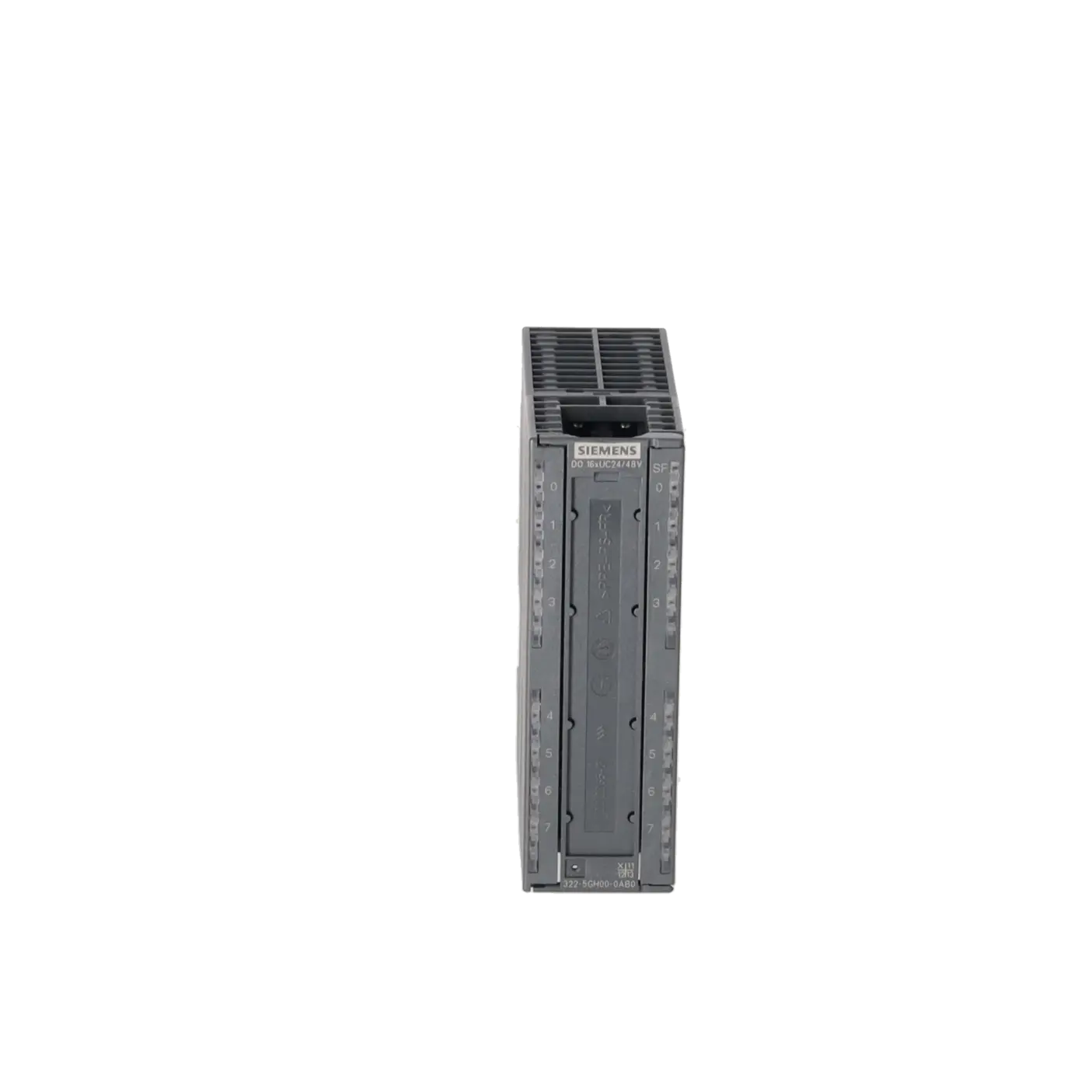
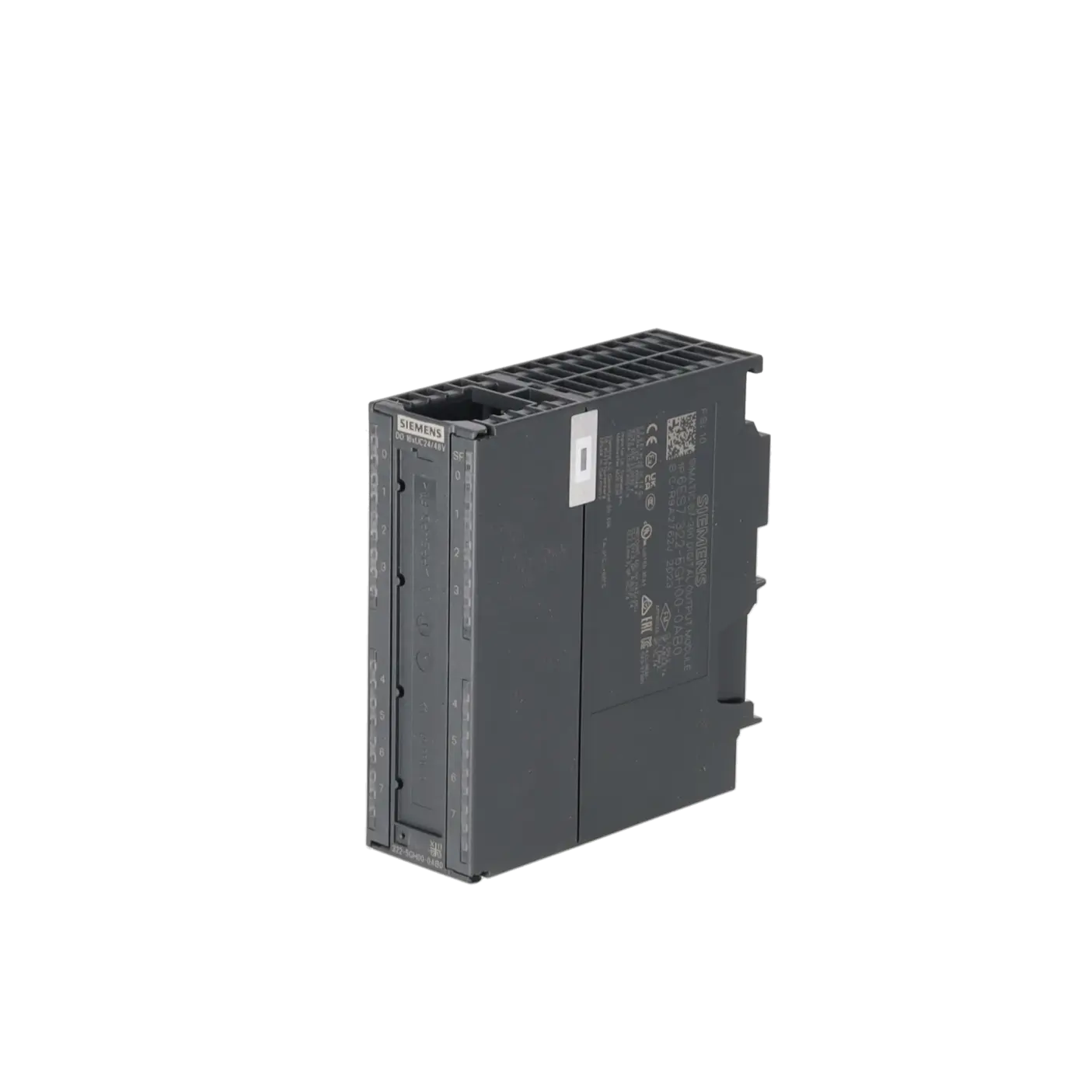
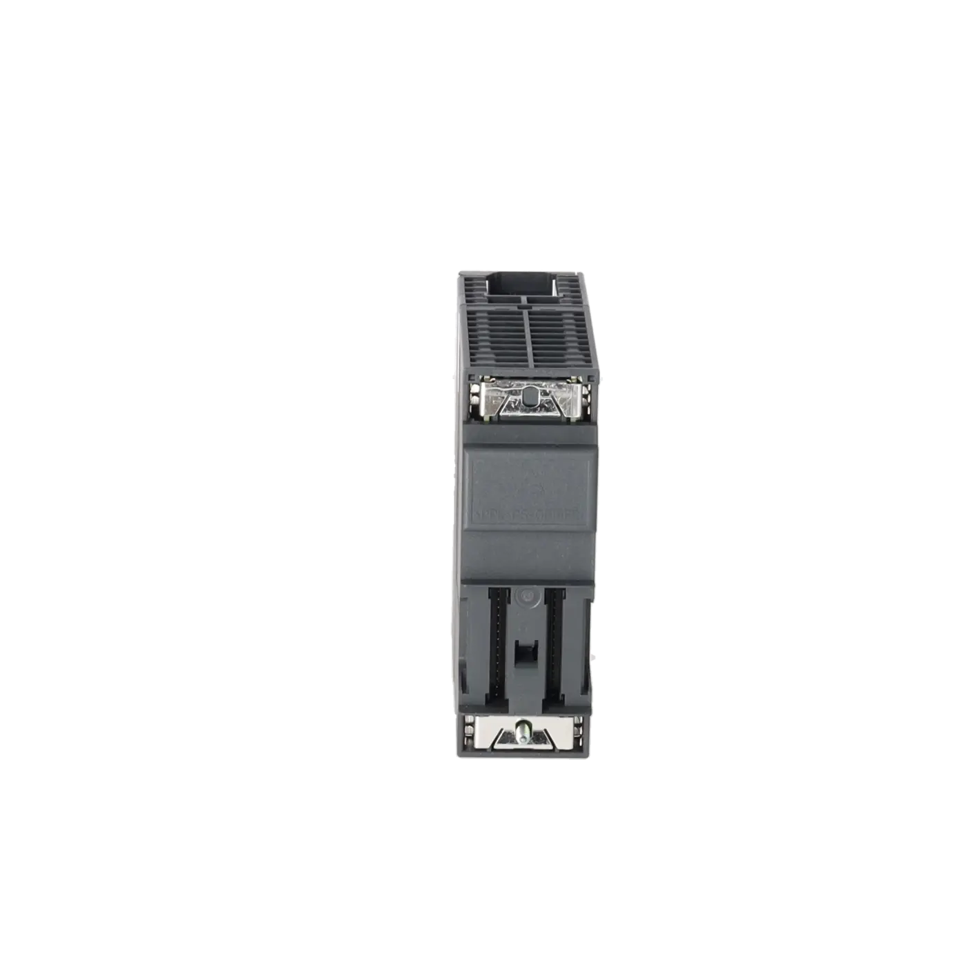
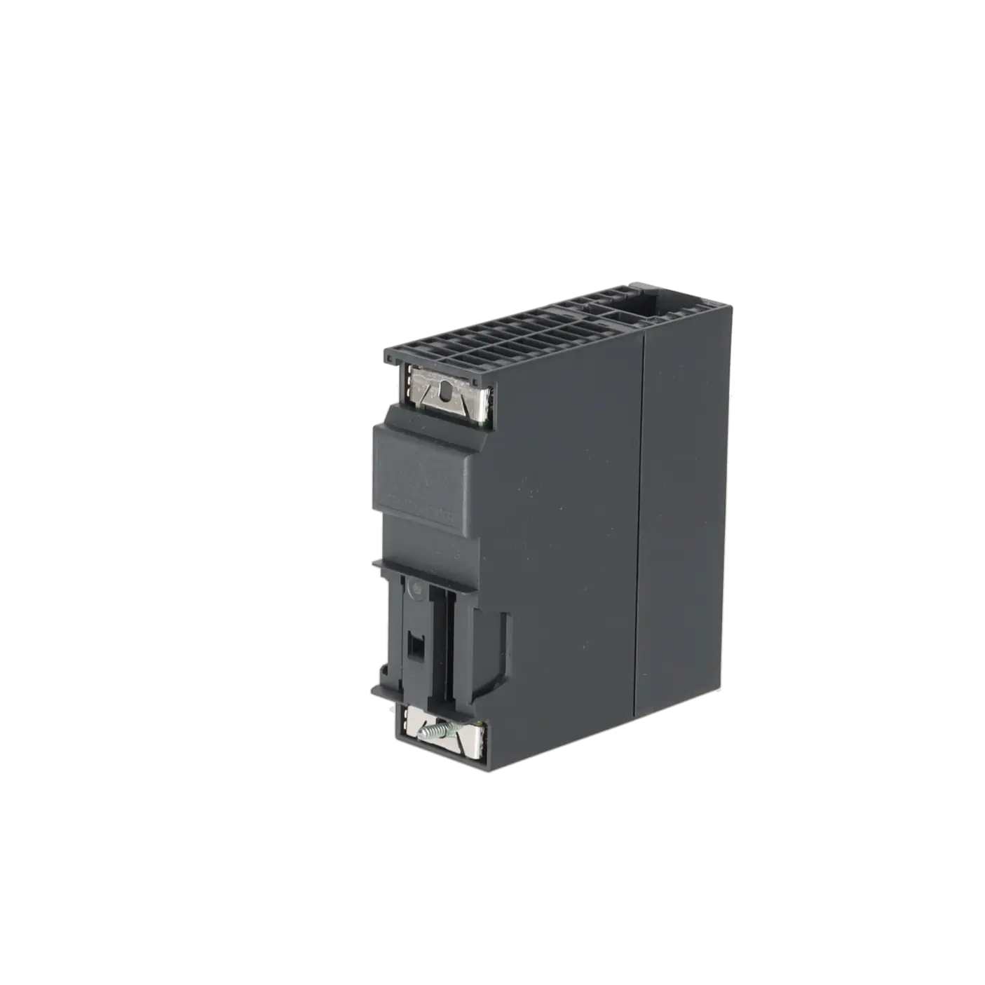
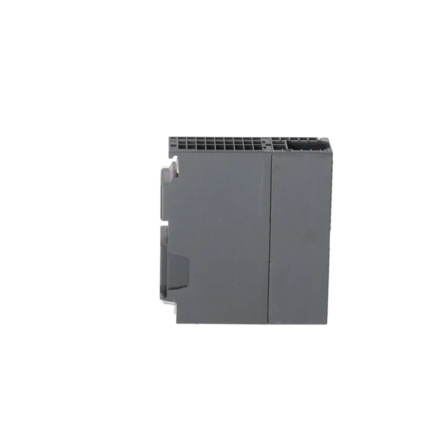
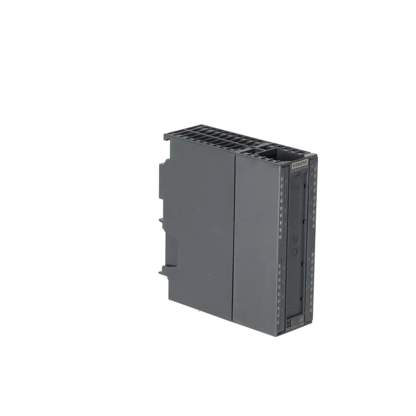
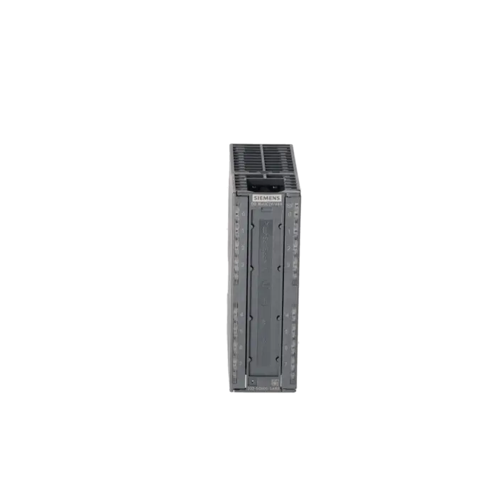
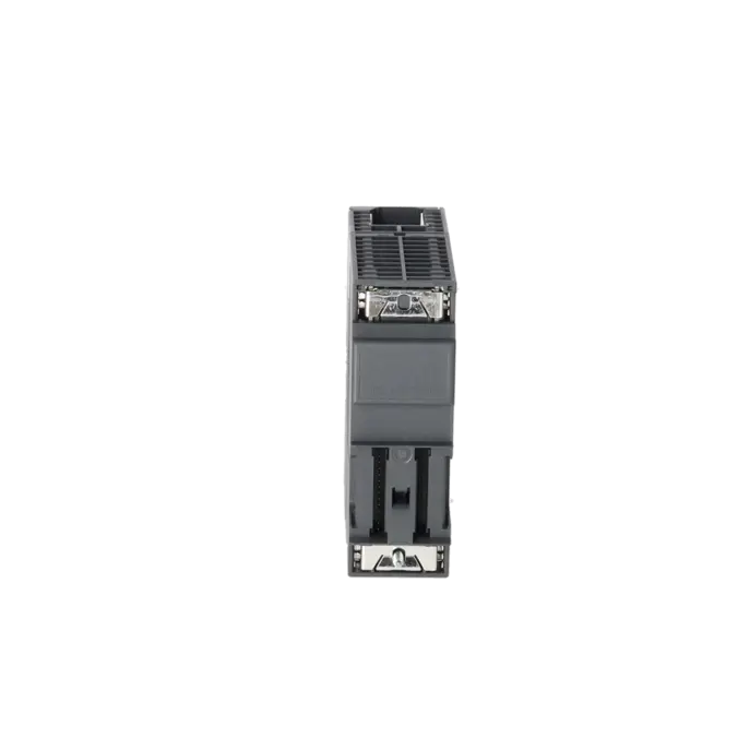
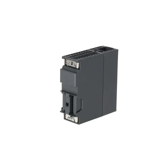
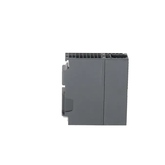
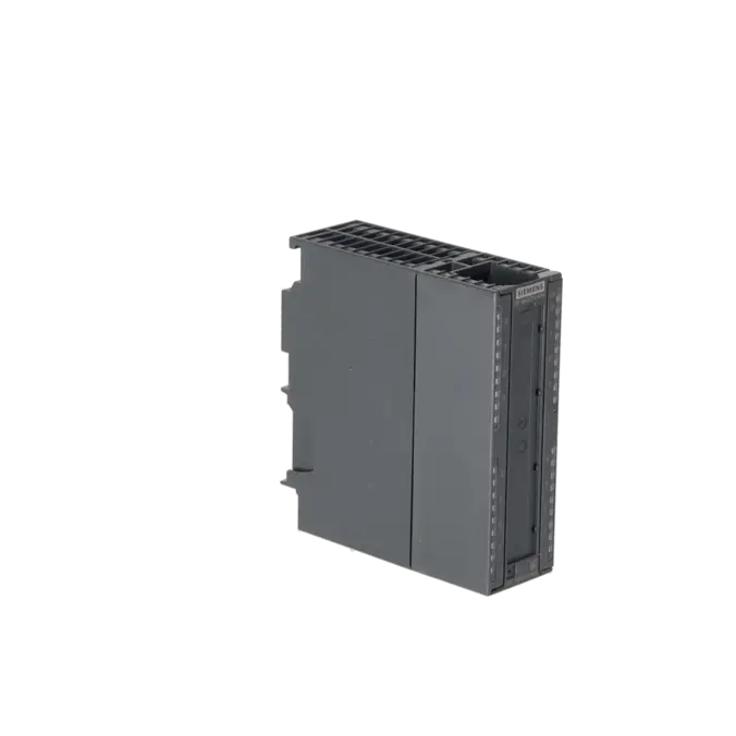
SIMATIC S7-300, DIGITAL OUTPUT SM 322, ISOLATED, 16 DO (SOLID-STATE RELAY), 24-48 V AC/DC; 0.5 A WITH SINGLE ROOTING, 1X 40-POLE
Services for SIEMENS 6ES7322-5GH00-0AB0
SIEMENS |
6ES7322-5GH00-0AB0 –
additional product information
| Delivery information | |||
|---|---|---|---|
| Export identifier | AL: N ECCN: N | ||
| Net weight | 0.314 | ||
| Quantity | 1 Stück | ||
| Packaging quantity | 1 | ||
| Additional product information | |||
|---|---|---|---|
| Product status | |||
| EAN | 4025515069959 | ||
| UPC | 662643171419 | ||
| Static lot number | 85389091 | ||
| List indicator | ST73 | ||
| Product group | 4561 | ||
| Country of origin | DE | ||
| Compliance with the substance restrictions according to RoHS directive | Since: 20100401 | ||
| Product classifications | Version | Classification | |
|---|---|---|---|
| eClass | 4 | 27-24-03-04 | |
| eClass | 5.1 | 27-24-22-04 | |
| eClass | 6.0 | 27-24-22-04 | |
| ETIM | 3 | / | |
| ETIM | 4 | EC001419 | |
| ETIM | 5 | EC001419 | |
What is 6ES7322-5GH00-0AB0 and where is it used?
6ES7322-5GH00-0AB0 is a SIEMENS SIMATIC S7-300 SM 322 digital output assembly with 16 digital outputs, galvanic isolation, and solid-state relay technology for 24 to 48 V AC/DC applications. The assembly is designed for applications where actuators need to be controlled safely and with galvanic isolation from an S7-300 station or within suitable ET 200M configurations. Typical applications include the switching of AC solenoid valves, actuators, motor starters, small motors, and signal lamps. For maintenance personnel, the article number is particularly important when an existing PLC station must be replaced with an identical unit, tested, or returned to service quickly after a failure.
Overview of the key technical data and what they mean
The assembly provides 16 outputs with a rated current of 0.5 A per output, requires a 40-pin front connector, and offers diagnostic-capable status and fault monitoring. The permissible load voltage ranges from 20.4 to 57.6 V DC, while the typical power dissipation is 2.8 W. In practice, this means that the assembly is well suited to compact switching tasks with moderate output currents where galvanic isolation, clear channel allocation, and diagnostic feedback are important. Siemens also specifies maximum cable lengths of 600 m unshielded and 1,000 m shielded, which are significant planning parameters for legacy systems with widely distributed actuators.
Product status, life cycle status and obsolescence
In the current Siemens datasheet, 6ES7322-5GH00-0AB0 is classified as a spare part. For purchasing and maintenance departments, this is an important indication that the assembly remains technically documented and available, but is no longer a focus of new platform strategies. In addition, this exact MLFB is listed in an EICHLER overview of SIMATIC S7-300 and ET 200M assemblies entering the discontinuation phase from 01/10/2025. For operators, this primarily means increasing procurement and stockholding risks. When planning replacements, not only availability but also testability, repairability, and stockholding strategy should be evaluated. The reviewed sources do not identify a clearly designated Siemens 1:1 successor for this assembly.
Available EICHLER services and when they are relevant
For 6ES7322-5GH00-0AB0, EICHLER offers several practical options to ensure long-term availability: Repair, Exchange, Used, and New. Repair is particularly relevant when an existing system should continue operating with an identical hardware status and project modifications are to be avoided. According to the product page, the repair service includes technical cleaning, preventive maintenance, comprehensive functional testing, and a minimum 24-month warranty. In addition, a test report for digital input/output assemblies is available. For purchasing teams, new units are attractive when identical hardware is required at short notice. For decision-makers, exchange and used-unit options are valuable tools for balancing downtime, obsolescence risks, and capital commitment. These services are intended exclusively for business customers.
| Attribute | Value |
|---|---|
| Supply voltage | |
| Mains buffering | |
| ● Mains/voltage failure stored energy time | 5 ms |
| Load voltage L+ | |
| ● Rated value (DC) | 24 V; 24 / 48 |
| ● permissible range, lower limit (DC) | 20.4 V |
| ● permissible range, upper limit (DC) | 57.6 V |
| ● Reverse polarity protection | Yes |
| Input current | |
| from supply voltage L+, max. | 200 mA |
| from backplane bus 5 V DC, max. | 100 mA |
| Power loss | |
| Power loss, typ. | 2.8 W |
| Digital outputs | |
| Number of digital outputs | 16 |
| Short-circuit protection | No; to be provided externally |
| Controlling a digital input | Yes |
| Size of motor starters according to NEMA, max. | Size 5 according to NEMA |
| Switching capacity of the outputs | |
| ● on lamp load, max. | 2.5 W |
| Output voltage | |
| ● for signal "1", min. | L+ (-0.25 V) |
| Output current | |
| ● for signal "1" rated value | 0.5 A |
| ● for signal "1" permissible range for 0 to 40 °C, max. | 0.5 A |
| ● for signal "1" permissible range for 40 to 60 °C, max. | 0.5 A |
| ● for signal "1" permissible surge current, max. | 1.5 A; for 50 ms, 1 A 2 s one-time |
| ● for signal "0" residual current, max. | 10 µA |
| Output delay with resistive load | |
| ● "0" to "1", max. | 6 ms |
| ● "1" to "0", max. | 3 ms |
| Parallel switching of two outputs | |
| ● for uprating | No |
| ● for redundant control of a load | Yes |
| Switching frequency | |
| ● with resistive load, max. | 10 Hz |
| ● with inductive load, max. | 0.5 Hz |
| ● with inductive load (acc. to IEC 60947-5-1, DC13), max. | 0.5 Hz |
| ● on lamp load, max. | 0.5 Hz |
| Total current of the outputs (per group) | |
| horizontal installation | |
| — up to 40 °C, max. | 0.5 A; 8 A per module |
| — up to 60 °C, max. | 0.5 A; 8 A per module |
| vertical installation | |
| — up to 40 °C, max. | 0.5 A; 8 A per module |
| Cable length | |
| ● shielded, max. | 1 000 m |
| ● unshielded, max. | 600 m |
| Interrupts/diagnostics/status information | |
| Diagnostics function | Yes; Parameterizable |
| Alarms | |
| ● Diagnostic alarm | Yes; Parameterizable |
| Diagnoses | |
| ● Diagnostic information readable | Yes |
| Diagnostics indication LED | |
| ● Group error SF (red) | Yes |
| ● Status indicator digital output (green) | Yes |
| Potential separation | |
| Potential separation digital outputs | |
| ● between the channels | Yes |
| ● between the channels, in groups of | 1 |
| ● between the channels and backplane bus | Yes; Optocoupler |
| ● between the channels and the power supply of the electronics | Yes |
| Isolation | |
| Isolation tested with | 1 500 V AC |
| Connection method | |
| required front connector | 40-pin |
| Dimensions | |
| Width | 40 mm |
| Height | 125 mm |
| Depth | 120 mm |
| Weights | |
| Weight, approx. | 260 g |
| Fault description | Possible solution |
|---|---|
| Why is the SF LED on the 6ES7322-5GH00-0AB0 illuminated red? | Siemens identifies several possible diagnostics for this assembly, including module faults, internal faults, external faults, missing auxiliary voltage, missing parameterisation, and incorrect parameters. Therefore, first check the L+ supply voltage, then verify the correct front connector wiring, followed by the hardware configuration in STEP 7 and the online module diagnostics. If the external supply voltage is missing, the assembly generally remains accessible via the backplane bus, but it will report a fault and will not switch loads as expected. |
| Why does an output of the 6ES7322-5GH00-0AB0 not switch even though the program is setting the signal? | With this SM 322 assembly, the actuators must be correctly wired via a 40-pin front connector, and the outputs must be externally protected. Check the load voltage, reference potential, front connector seating, and load wiring. If the output LED switches but the field load does not respond, the cause is often a missing load supply, a wiring fault, or a defect in either the output stage or the connected load circuit. |
| Why does STEP 7 report "Module not parameterised" or "Incorrect parameters" for the 6ES7322-5GH00-0AB0? | Siemens explicitly lists both conditions in the assembly's system diagnostics. Typical causes include a hardware configuration that does not match the installed assembly, an incompletely downloaded hardware configuration, or the replacement of the assembly with a different variant number without updating the project. The solution is to verify the exact MLFB, download the hardware configuration again, and check whether the diagnostic parameters and the configured behaviour during CPU STOP are correctly set. |
| Why do the outputs behave differently than expected after a CPU STOP or a brief power interruption? | The assembly supports parameterisable behaviour and can, depending on the configuration, output substitute values or maintain the last valid state. Siemens also specifies a power failure bridging time of 5 ms. Therefore, if unexpected switching behaviour occurs, check how the module has been configured for CPU STOP, restart behaviour, and substitute value generation. Particularly in legacy systems, poorly documented parameter settings often result in actual output behaviour differing from the expected control logic. |
What exactly does the 6ES7322-5GH00-0AB0 do?
The 6ES7322-5GH00-0AB0 is a 16-channel digital output assembly from the SIMATIC S7-300 range. It converts PLC control signals into switching operations for field loads and is designed for 24 to 48 V AC/DC applications with 0.5 A per output. Thanks to its galvanically isolated solid-state relay outputs, the assembly is particularly suitable for applications where clean galvanic isolation and reliable signal switching are more important than high switching currents.
Which loads can I switch with the 6ES7322-5GH00-0AB0?
Siemens describes the assembly as suitable for AC solenoid valves, actuators, motor starters, small motors, and signal lamps. The key requirement is that the load matches both the voltage type and the current rating of the assembly. For purchasing and maintenance departments, this means that not only the article number but also the actual field load must be considered. Particularly in legacy systems, it is advisable to verify that the inrush current, switching frequency, and wiring configuration remain within the specified limits before replacing the assembly.
Which front connector is required for the 6ES7322-5GH00-0AB0?
A 40-pin front connector is required for this assembly. Siemens lists, among others, the 40-pin front connector with screw terminals, 6ES7392-1AM00-0AA0, for this purpose. In practice, it is also important to check which connection technology is already installed in the system and whether sufficient installation space is available for the wiring. For a rapid replacement, the correct front connector assignment is often just as important as the assembly itself.
Is 6ES7322-5GH00-0AB0 still available or already obsolete?
Current Siemens documentation lists the assembly as a spare part. At the same time, the MLFB appears in an EICHLER overview of S7-300 and ET 200M assemblies entering the discontinuation phase from 01/10/2025. In practice, this means that the part has not automatically disappeared from the market, but the supply risk is increasing. Anyone wishing to secure long-term system availability should therefore plan for repair, exchange, used stock, and strategic stockholding at an early stage.
Can I also use the 6ES7322-5GH00-0AB0 in an ET 200M station?
The assembly is listed in Siemens documentation both within the SIMATIC S7-300 range and in ET 200M-related module overviews. However, actual compatibility depends on the specific IM 153 variant, the installed hardware revision, and the project configuration. For service and procurement purposes, this means that not only the assembly MLFB but also the existing ET 200M configuration should be checked before replacement to ensure mechanical, electrical, and project-level compatibility.
When is repair more sensible than purchasing a new unit for the 6ES7322-5GH00-0AB0?
Repair is particularly worthwhile when a legacy system is to continue operating with an identical functional status and without any project modifications, or when the availability of new parts is uncertain. Purchasing a new unit is the preferred option when an immediately deployable assembly is required and suitable stock is available. On the EICHLER product page, Repair, Exchange, Used, and New options are available for this model. The repair service includes technical cleaning, preventive maintenance, functional testing, and a minimum 24-month warranty.