SIEMENS 6ES7322-1HH01-0AA0
-
SIEMENS | PLC Controls | Digital Input / Output Modules
- EICHLER-art.no.: K0118553
- EAN: 4025515067412
- UPC: 662643170993
Product description
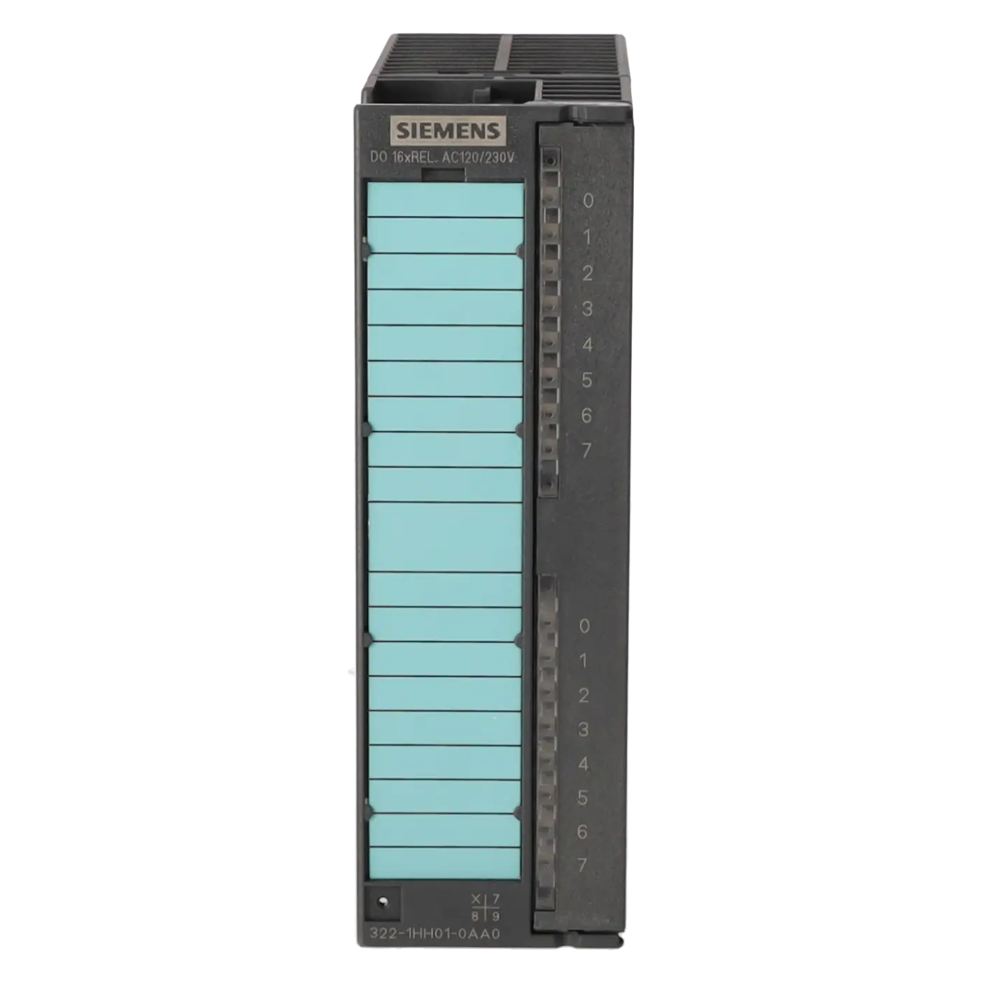
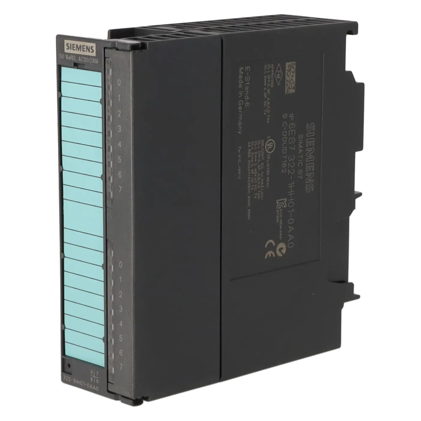
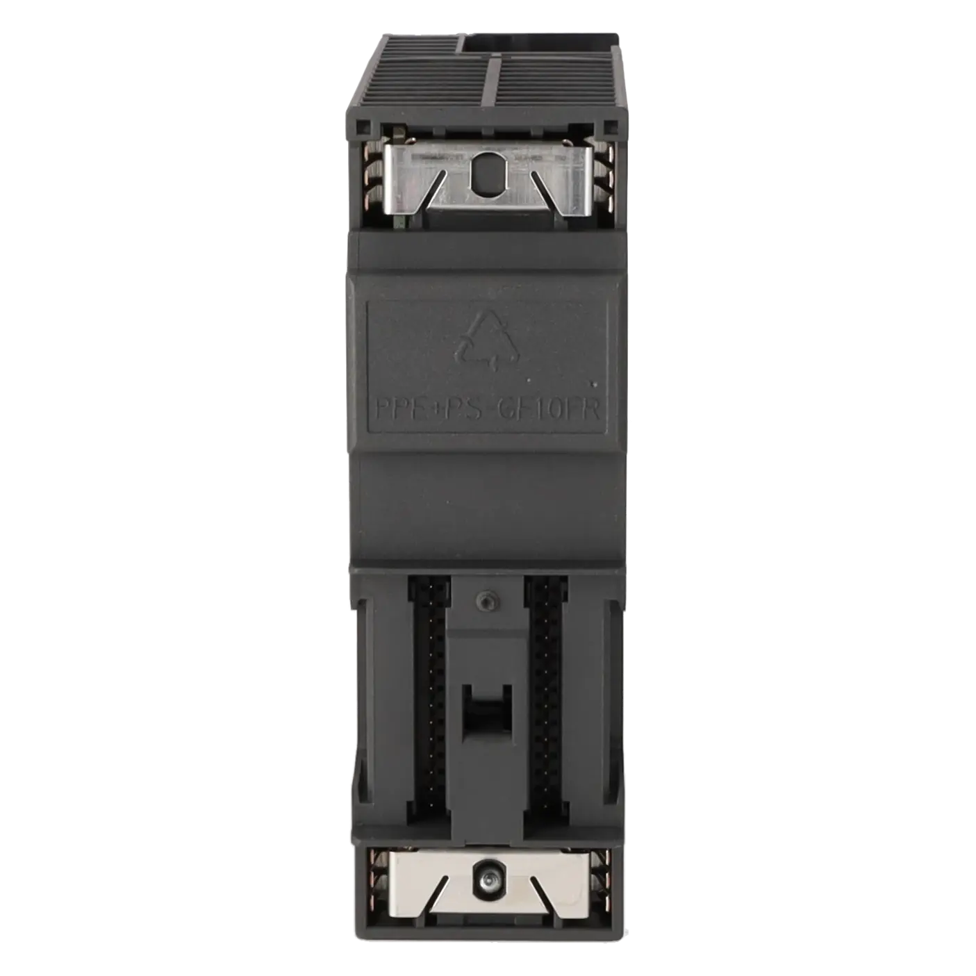
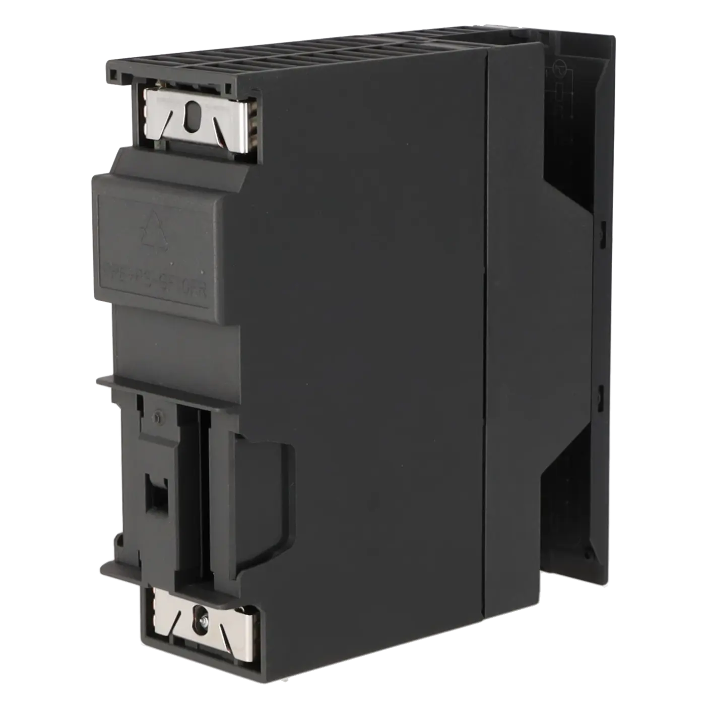
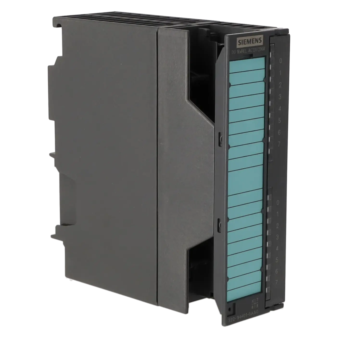
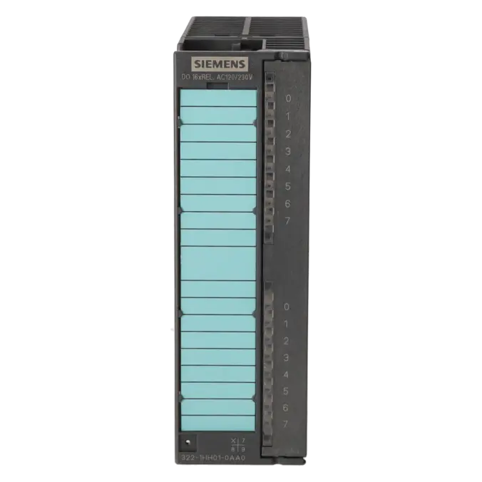
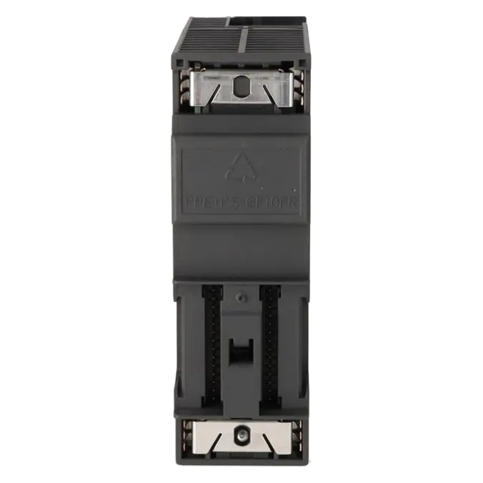
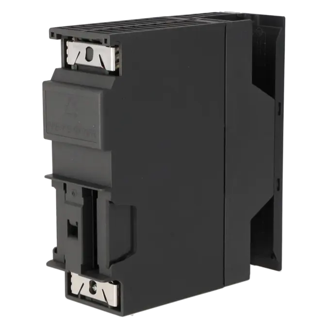
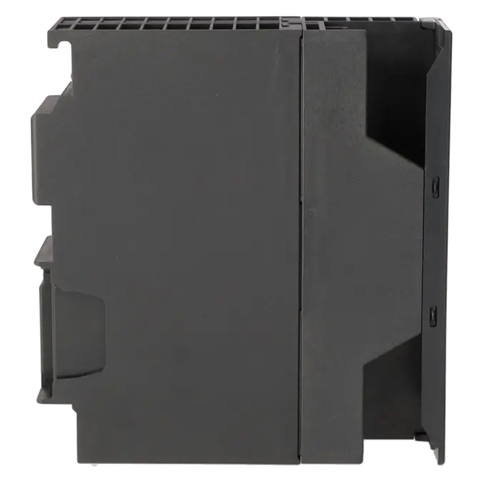
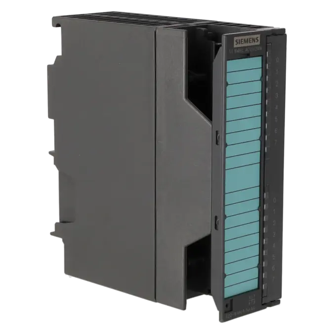
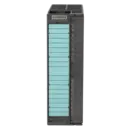
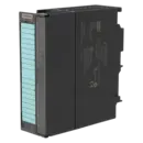
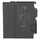
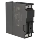
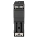
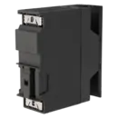
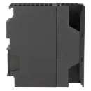
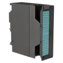
SIMATIC S7-300, digital output SM 322, isolated 16 DO, relay contacts, 1x 20-pole
Services for SIEMENS 6ES7322-1HH01-0AA0
Repair
from 383,50 €
to 690,30 €
Replacement
506,09 €
379,57 €
Used
562,32 €
421,74 €
New
624,80 €
468,60 €
SIEMENS |
6ES7322-1HH01-0AA0 –
additional product information
| Delivery information | |||
|---|---|---|---|
| Export identifier | AL: N ECCN: N | ||
| Net weight | 0.276 | ||
| Quantity | 1 Stück | ||
| Packaging quantity | 1 | ||
| Additional product information | |||
|---|---|---|---|
| Product status | EOP: 2025-10-01 | ||
| EAN | 4025515067412 | ||
| UPC | 662643170993 | ||
| Static lot number | 85389091 | ||
| List indicator | ST73 | ||
| Product group | 4561 | ||
| Country of origin | DE | ||
| Compliance with the substance restrictions according to RoHS directive | Since: 20080331 | ||
| Product classifications | Version | Classification | |
|---|---|---|---|
| eClass | 4 | 27-24-03-04 | |
| eClass | 5.1 | 27-24-22-04 | |
| eClass | 6.0 | 27-24-22-04 | |
| ETIM | 3 | / | |
| ETIM | 4 | EC001419 | |
| ETIM | 5 | EC001419 | |
What is 6ES7322-1HH01-0AA0 and where is it used?
The 6ES7322-1HH01-0AA0 is a SIMATIC S7-300 SM 322 digital output module with 16 electrically isolated relay outputs and one 20-pin front connector. The module is used in automation systems where actuators must be switched with galvanic isolation, such as solenoid valves, contactors, motor starters, small motors, and signal lamps.
Thanks to its relay output technology, the module is suitable for both AC and DC loads, making it a practical choice where standard 24 V transistor outputs are insufficient or where robust isolation between the controller and the load side is required. Typical applications include production lines, conveyor systems, machine-building projects, retrofit applications, and existing S7-300 or ET 200M installations.
Overview of the key technical specifications and what they mean
The module provides 16 relay outputs, arranged in two electrically isolated groups of eight channels. The load side supports 24 to 120 V DC and 24 to 230 V AC. Each output can switch up to 2 A, while the maximum total current per group is 8 A.
An important practical consideration is that the module offers no short-circuit protection and no diagnostic functions for wire break, short circuit, blown fuse, or missing load voltage. The only built-in indication consists of green status LEDs for each channel.
In addition, the relay coils require a separate 24 V DC supply voltage (L+). For maintenance personnel and purchasing departments, this means the module is robust and highly versatile, but troubleshooting relies on proper wiring checks, load verification, and manual measurements rather than integrated diagnostics.
Product status, lifecycle status, and obsolescence
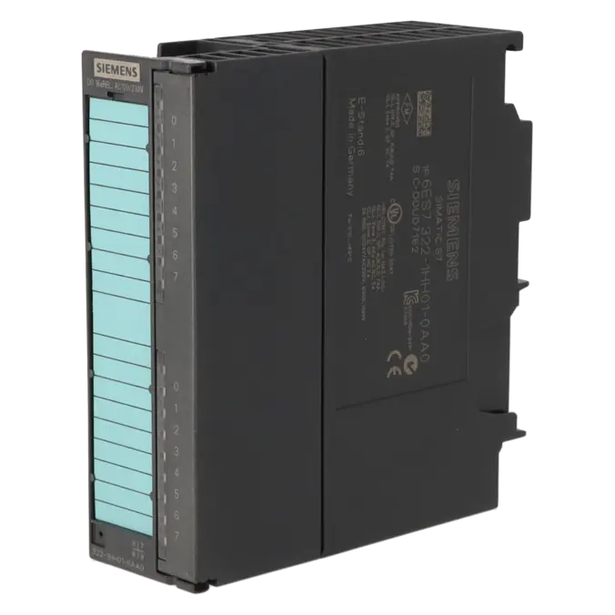
Siemens currently classifies the 6ES7322-1HH01-0AA0 as a spare part. The Product Phase-Out Announcement was issued on 1 October 2023, while Product Cancellation is specified as 1 October 2025. The EICHLER product page likewise lists the module with EOP: 2025-10-01.
For operators of existing S7-300 and ET 200M systems, this means the module remains important for ongoing operation but should be included in an active spare-parts and obsolescence strategy. Siemens does not identify a direct plug-and-play replacement within the S7-300 platform for this specific module. While migration targets exist for newer platforms, they are not direct 1:1 replacement modules.
Available EICHLER services and when they are relevant
For the 6ES7322-1HH01-0AA0, EICHLER offers repair, exchange, and new units. The product page currently indicates 2–5 days for repair and 1–3 days for exchange or new units.
The repair service includes technical cleaning, preventive maintenance, comprehensive functional testing, and a minimum 24-month warranty. An optional test report for digital inputs and outputs is also available.
For maintenance teams, repair is often the preferred option when an existing S7-300 installation is expected to remain in service and downtime must be managed economically. For purchasing departments, exchange units can be advantageous when restoring production quickly is the highest priority. For decision-makers, the combination of repair, exchange, and tested replacement hardware provides an effective way to maintain operational reliability despite the module's advancing obsolescence.
| Attribute | Value |
|---|---|
| Supply voltage | |
| Load voltage L+ | |
| ● Rated value (DC) | 120 V |
| Load voltage L1 | |
| ● Rated value (AC) | 230 V |
| Input current | |
| from supply voltage L+, max. | 250 mA |
| from backplane bus 5 V DC, max. | 100 mA |
| Power loss | |
| Power loss, typ. | 4.5 W |
| Digital outputs | |
| Number of digital outputs | 16; Relays |
| Short-circuit protection | No |
| Controlling a digital input | Yes |
| Size of motor starters according to NEMA, max. | Size 5 according to NEMA |
| Switching capacity of the outputs | |
| ● on lamp load, max. | 50 W; 230 V AC |
| Output current | |
| ● for signal "1" rated value | 2 A |
| ● for signal "1" minimum load current | 10 mA |
| Parallel switching of two outputs | |
| ● for uprating | No |
| ● for redundant control of a load | Yes |
| Switching frequency | |
| ● with resistive load, max. | 1 Hz |
| ● with inductive load, max. | 0.5 Hz |
| ● With inductive load (to IEC 60947-5-1, DC13/AC15), max. | 0.5 Hz |
| ● on lamp load, max. | 1 Hz |
| ● mechanical, max. | 10 Hz |
| Total current of the outputs (per group) | |
| horizontal installation | |
| — up to 60 °C, max. | 8 A |
| vertical installation | |
| — up to 40 °C, max. | 8 A |
| Relay outputs | |
| ● Rated supply voltage of relay coil L+ (DC) | 24 V |
| ● Contact connection (internal) | No |
| ● Number of operating cycles, max. | 100 000; 50 000 (24 V DC, at 2 A); 700 000 (120 V AC, at 2 A); 100 000 (230 V AC, at 2 A) |
| Switching capacity of contacts | |
| — with inductive load, max. | 2 A; 2 A (230 V AC), 2 A (24 V DC) |
| — with resistive load, max. | 2 A; 2 A (230 V AC), 2 A (24 V DC) |
| — Thermal continuous current, max. | 2 A |
| Cable length | |
| ● shielded, max. | 1 000 m |
| ● unshielded, max. | 600 m |
| Interrupts/diagnostics/status information | |
| Alarms | No |
| Diagnostics function | No |
| Alarms | |
| ● Diagnostic alarm | No |
| Diagnoses | |
| ● Wire break | No |
| ● Short-circuit | No |
| ● Fuse blown | No |
| ● missing load voltage | No |
| Diagnostics indication LED | |
| ● Rated load voltage PWR (green) | No |
| ● Fuse OK FSG (green) | No |
| ● Status indicator digital output (green) | Yes |
| Potential separation | |
| Potential separation digital outputs | |
| ● between the channels | Yes |
| ● between the channels, in groups of | 8 |
| ● between the channels and backplane bus | Yes; Optocoupler |
| Isolation | |
| Isolation tested with | 1 500 V AC |
| Connection method | |
| required front connector | 20-pin |
| Dimensions | |
| Width | 40 mm |
| Height | 125 mm |
| Depth | 120 mm |
| Weights | |
| Weight, approx. | 250 g |
| Fault description | Possible solution |
|---|---|
| Why is the output LED illuminated, but the contactor or valve does not energise? | First measure the load side directly at the module and check the wiring. The status LED only indicates the switching state of the channel, not the actual presence of load voltage. Also verify that the 24 V supply for the relay coils is present, that the load remains within the permitted current limits, and that the relay contact has not already been damaged by wear or overload. |
| Why does the 6ES7322-1HH01-0AA0 not switch at all, even though the program sets the output? | Check the hardware configuration and addressing, reload the complete configuration, and verify that the output is not being written by multiple program sections or overwritten by other logic. Then measure the voltage at L+ and M and test the load directly at the module. In existing installations, address conflicts, incomplete hardware downloads, or wiring faults are often more common causes than an actual module failure. |
| Why is there permanent voltage on an output even though the output should be off? | In this situation, a welded or mechanically damaged relay contact is the most likely cause. The risk increases when switching unsuitable loads, inductive loads without adequate suppression circuitry, or loads operating close to the module limits. Disconnect the load, measure the contact condition separately, and have the module inspected. Since the module has no internal contact protection, repair or replacement is often more economical than spending excessive time searching for a software-related cause. |
| Why does the CPU not report a diagnostic fault even though an output is not working? | This module provides no diagnostic functions for short circuits, wire breaks, blown fuses, or missing load voltage. As a result, a fault in the load circuit often does not generate any diagnostic alarm in the CPU. Troubleshooting must therefore be carried out through voltage measurements, wiring checks, load testing, and comparison with a known working channel. |
| Why do outputs behave unexpectedly for a short time when the power supply is switched off? | Siemens states that the internal buffer capacitance can provide enough energy for approximately 200 ms, allowing the user program to set a defined relay state during power-down. If loads react unexpectedly during this period, the shutdown logic, interlocks, and safe isolation of the load circuits should be reviewed to ensure the application behaves as intended. |
Is 6ES7322-1HH01-0AA0 still available or only as a spare part?
Siemens classifies the module as a spare part in its documentation. At the same time, the current EICHLER product page shows that repair, exchange, and new units are still available for this article number. For procurement, this means that the market has not disappeared completely, but the module clearly belongs to the area of installed-base support and obsolescence management. Anyone planning purchases should secure availability and a spare-parts strategy early rather than waiting for a failure to occur.
Can I replace 6ES7322-1HH00-0AA0 with 6ES7322-1HH01-0AA0?
Yes. Siemens has documented that the earlier signal module 6ES7322-1HH00-0AA0 was revised and replaced by the new order number 6ES7322-1HH01-0AA0. A Siemens notice also states that when reusing the old front connector, the locking elements must be removed. For existing installations, this is important because it makes replacement within the existing platform much easier to plan.
What types of loads is the module suitable for?
The SM 322 is designed for AC/DC solenoid valves, contactors, motor starters, fractional-horsepower motors, and indicator lamps. Up to 2 A per output is permitted, although the load type and switching frequency must be taken into account. Different conditions apply for resistive and inductive loads. Siemens specifies a maximum lamp load of 50 W at 230 V AC. In practice, this makes the module ideal for conventional switching tasks in machinery and industrial systems, but not for arbitrarily high or highly dynamic loads.
Are diagnostic functions available for wire break, short circuit, or missing load voltage?
No. This is an important consideration for maintenance personnel. The module provides no diagnostic functions for wire break, short circuit, blown fuse, or missing load voltage. Only the channel status LEDs are available. Therefore, when troubleshooting, it is not enough to rely solely on CPU diagnostics. The load circuits should be measured directly and the wiring checked systematically. In this case, electrical measurement is usually faster and more effective than software diagnostics alone.
Is there a direct successor to 6ES7322-1HH01-0AA0?
There is no manufacturer-designated 1:1 successor for this article number within the existing S7-300/ET 200M architecture. However, Siemens identifies other target modules in its migration documentation, including 6ES7522-5FF00-0AB0 for S7-1500 projects and 6DL1132-6HD50-0PK0 for ET 200SP HA environments. These references are useful for retrofit planning, but they do not replace the original module without system modifications.
When is repair more sensible than exchange or purchasing a new unit?
Repair is the preferred option when the existing S7-300 installation is to remain in service and the original module can be restored economically. Exchange is more suitable when the system must be returned to operation as quickly as possible and a tested replacement unit offers the shortest downtime. Purchasing a new unit is attractive when stock is still available and standardisation is required. Since Siemens already treats the module as part of its spare-parts and discontinuation programme, the combination of repair capability, short availability, and functional testing is often the safest way for operators to minimise unplanned downtime.