
SIEMENS 6ES7322-1HF10-0AA0
-
SIEMENS | PLC Controls | Digital Input / Output Modules
- EICHLER-art.no.: K0118551
- EAN: 4025515061038
- UPC: 662643170986
Product description
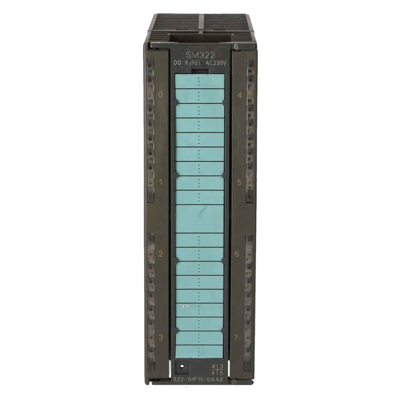
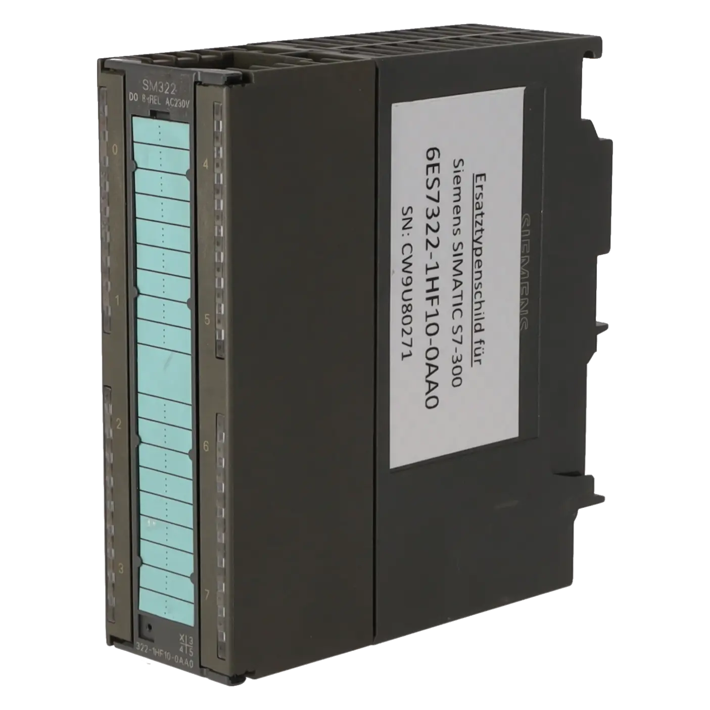
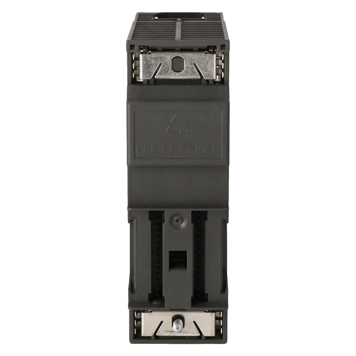
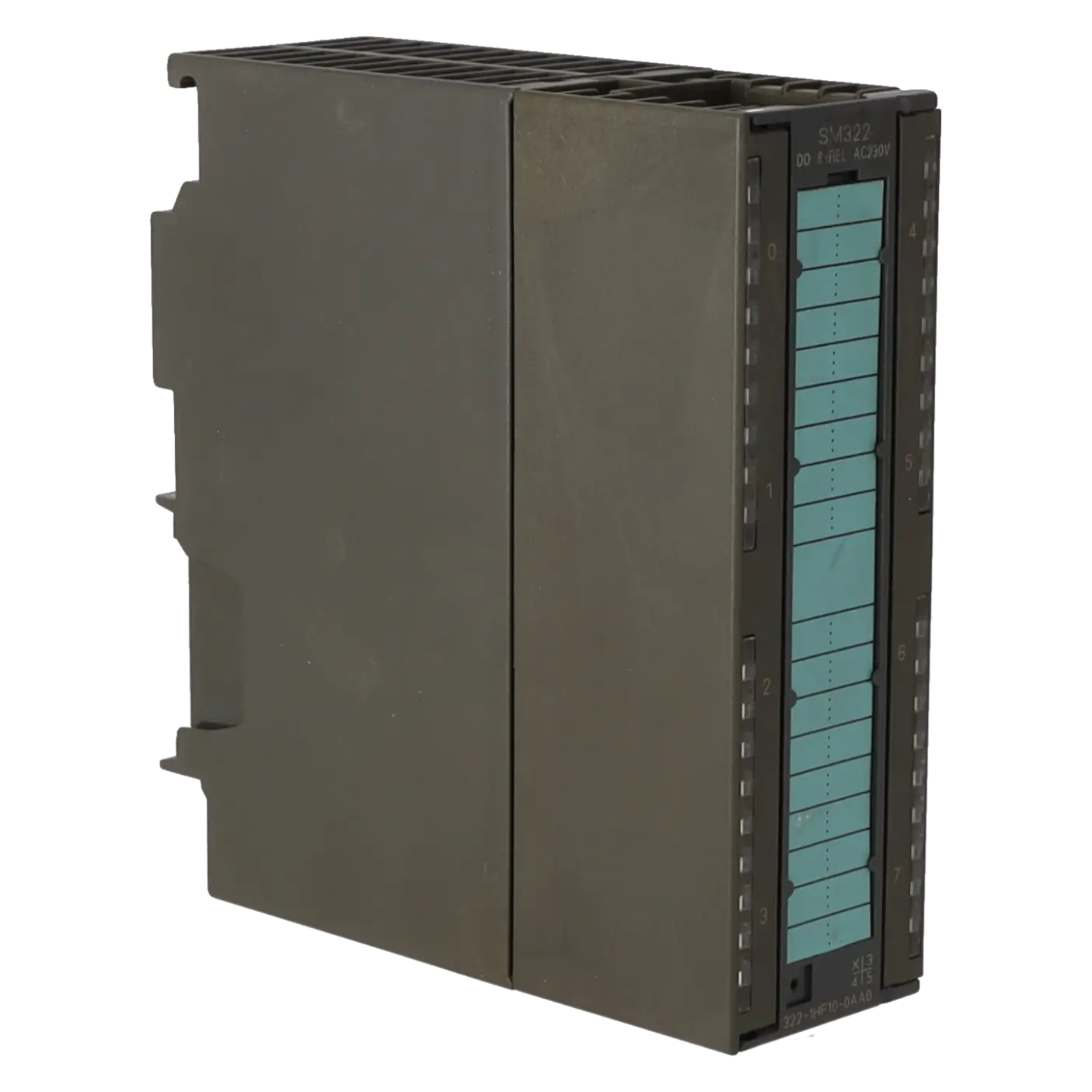
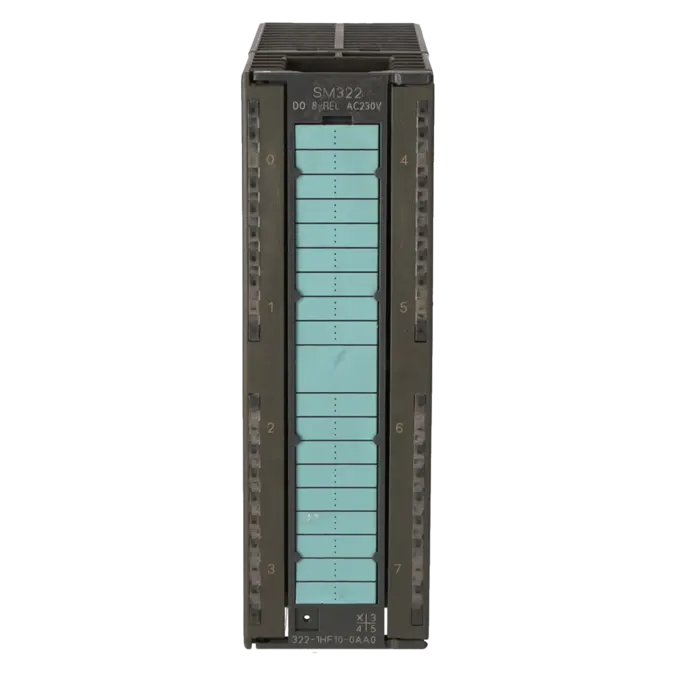
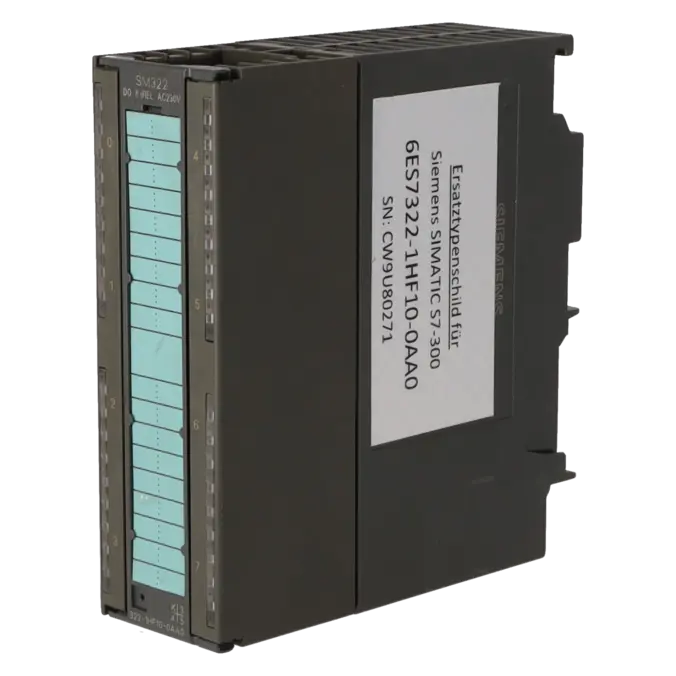
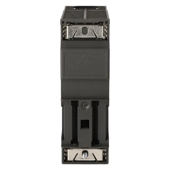
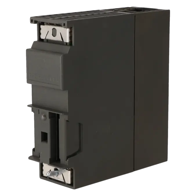
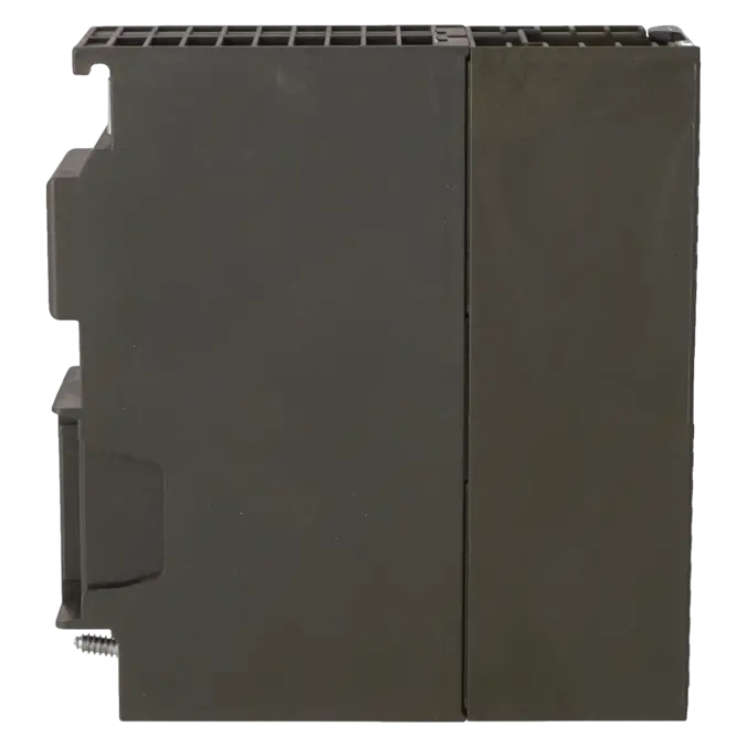
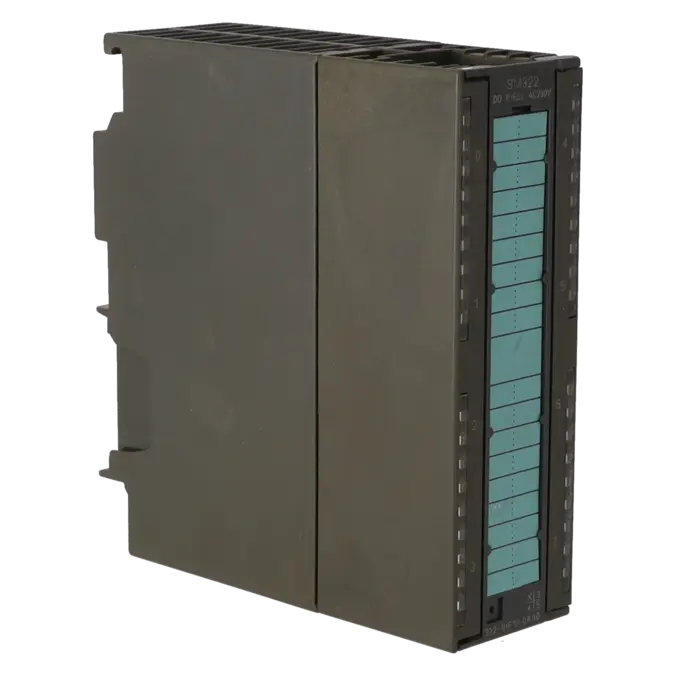
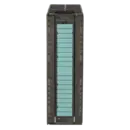
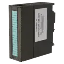
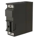
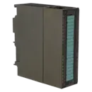
SIMATIC S7-300, DIGITAL OUTPUT SM 322, ISOLATED, 8 DO (RELAY), 1X 40-POLE, 24 V DC, 5 A OR 230 V AC, 5 A, CONNECTORS WITH SPRING-LOADED TERMINAL CAN BE USED AS OF 6ES7392-1BM01-0AA0
Services for SIEMENS 6ES7322-1HF10-0AA0
SIEMENS |
6ES7322-1HF10-0AA0 –
additional product information
| Delivery information | |||
|---|---|---|---|
| Export identifier | AL: N ECCN: N | ||
| Net weight | 0.367 | ||
| Quantity | 1 Stück | ||
| Packaging quantity | 1 | ||
| Additional product information | |||
|---|---|---|---|
| Product status | EOP: 2025-10-01 | ||
| EAN | 4025515061038 | ||
| UPC | 662643170986 | ||
| Static lot number | 85389091 | ||
| List indicator | ST73 | ||
| Product group | 4561 | ||
| Country of origin | DE | ||
| Compliance with the substance restrictions according to RoHS directive | Since: 20080331 | ||
| Product classifications | Version | Classification | |
|---|---|---|---|
| eClass | 4 | 27-24-03-04 | |
| eClass | 5.1 | 27-24-22-04 | |
| eClass | 6.0 | 27-24-22-04 | |
| ETIM | 3 | / | |
| ETIM | 4 | EC001419 | |
| ETIM | 5 | EC001419 | |
What is 6ES7322-1HF10-0AA0 and where is it used?
6ES7322-1HF10-0AA0 is an SM 322 digital output module from the Siemens SIMATIC S7-300 family. The module provides 8 relay outputs and is designed for applications where actuators with different load types must be switched reliably. Typical applications include solenoid valves, contactors, motor contactors, indicator lamps, and other field loads within control cabinets. Thanks to its relay technology, the assembly is particularly attractive in legacy systems where both 24 V DC and 230 V AC loads are present. The module can be used not only in a central S7-300 system but also in ET 200M stations using compatible S7-300 modules.
Overview of the key technical data and what they mean
The assembly features 8 individually isolated relay outputs and requires 24 V DC L+ for the relay coils. It can switch loads up to 120 V DC or 230 V AC with a rated current of 5 A per output. According to the datasheet, contact loads of up to 8 A are possible with resistive loads, while inductive loads are limited to 3 A. Important in practice: this is not a diagnostic module. It does not provide short-circuit detection, wire-break monitoring, fuse diagnostics, or load-voltage monitoring, but only green status LEDs for each channel. Also relevant is the requirement for a 40-pin front connector, while the module itself has a typical power dissipation of 3.2 W.
Product status, life cycle status and obsolescence
For operators of legacy systems, the lifecycle status is particularly important. Siemens lists the 6ES7322-1HF10-0AA0 as a spare part and specifies the lifecycle status PM410 / Product Cancellation, effective from 01 October 2025. The EICHLER product page also identifies the module with an EOP (End of Product) date of 01 October 2025. For purchasing and maintenance departments, this means that although the module remains available on the market, the risk associated with procurement increases, particularly in cases of unexpected failures, production stoppages, or spare-parts shortages. For migration projects, Siemens references the 6DL1132-6HD50-0PK0 as a target module within the ET 200SP HA upgrade context; however, this should not be regarded as a universal 1:1 replacement without first evaluating the wiring, diagnostic behaviour, and station architecture.
Available EICHLER services and when they are relevant
For companies operating S7-300 legacy systems, the services offered on the EICHLER product page are particularly practical. Repair is a suitable option when an existing module must be returned to operation quickly while keeping the application unchanged. EICHLER specifies a typical turnaround time of 2–5 days and includes services such as technical cleaning, preventive maintenance, comprehensive functional testing, and a minimum 24-month warranty. Exchange units and used modules are particularly attractive when downtime costs exceed the repair time. New units are relevant when a defined procurement route is required for stockholding or urgent replacement needs; the product page currently indicates a delivery time of 1–3 days. In cases of obsolescence, these options help maintain system availability despite the product's phase-out status.
| Attribute | Value |
|---|---|
| Supply voltage | |
| Load voltage L+ | |
| ● Rated value (DC) | 120 V |
| Load voltage L1 | |
| ● Rated value (AC) | 230 V |
| Input current | |
| from supply voltage L+, max. | 125 mA |
| from backplane bus 5 V DC, max. | 40 mA |
| Power loss | |
| Power loss, typ. | 3.2 W |
| Digital outputs | |
| Number of digital outputs | 8; Relays |
| Short-circuit protection | No; to be provided externally |
| Controlling a digital input | Yes |
| Switching capacity of the outputs | |
| ● on lamp load, max. | 1 500 W; 230 V AC |
| ● Low energy/fluorescent lamps with electronic control gear | 10x 58 W |
| ● Fluorescent tubes, conventionally compensated | 1x 58 W |
| ● Fluorescent tubes, uncompensated | 10x 58 W |
| Output current | |
| ● for signal "1" rated value | 5 A |
| ● for signal "1" minimum load current | 5 mA |
| Parallel switching of two outputs | |
| ● for uprating | No |
| ● for redundant control of a load | Yes |
| Switching frequency | |
| ● with resistive load, max. | 2 Hz |
| ● with inductive load, max. | 0.5 Hz |
| ● With inductive load (to IEC 60947-5-1, DC13/AC15), max. | 0.5 Hz |
| ● on lamp load, max. | 2 Hz |
| ● mechanical, max. | 10 Hz |
| Total current of the outputs (per group) | |
| horizontal installation | |
| — up to 60 °C, max. | 5 A |
| vertical installation | |
| — up to 40 °C, max. | 5 A |
| Relay outputs | |
| ● Rated supply voltage of relay coil L+ (DC) | 24 V |
| ● Contact connection (internal) | No |
| ● Number of operating cycles, max. | 300 000; 300 000 (24 V DC, at 2 A); 200 000 (120 V AC, at 3 A); 100 000 (230 V AC, at 3 A) |
| Switching capacity of contacts | |
| — with inductive load, max. | 3 A; 3 A (230 V DC), 2 A (24 V AC) |
| — with resistive load, max. | 8 A; 8 A (230 V DC), 5 A (24 V AC) |
| — Thermal continuous current, max. | 8 A |
| Cable length | |
| ● shielded, max. | 1 000 m |
| ● unshielded, max. | 600 m |
| Interrupts/diagnostics/status information | |
| Alarms | No |
| Diagnostics function | No |
| Alarms | |
| ● Diagnostic alarm | No |
| Diagnoses | |
| ● Wire break | No |
| ● Short-circuit | No |
| ● Fuse blown | No |
| ● missing load voltage | No |
| Diagnostics indication LED | |
| ● Rated load voltage PWR (green) | No |
| ● Fuse OK FSG (green) | No |
| ● Status indicator digital output (green) | Yes |
| Potential separation | |
| Potential separation digital outputs | |
| ● between the channels | Yes |
| ● between the channels, in groups of | 1 |
| ● between the channels and backplane bus | Yes; Optocoupler |
| Isolation | |
| Isolation tested with | 2 000 V AC |
| Connection method | |
| required front connector | 40-pin |
| Dimensions | |
| Width | 40 mm |
| Height | 125 mm |
| Depth | 120 mm |
| Weights | |
| Weight, approx. | 320 g |
| Fault description | Possible solution |
|---|---|
| Why does the 6ES7322-1HF10-0AA0 not switch the output even though the PLC program writes a 1? | First check the 24 V DC L+ supply for the relay coils at both the module and the front connector. The module can only energise its relays when this supply voltage is present and stable. Next, force or set the channel in STEP 7 and simultaneously monitor the channel LED while measuring the voltage directly in the load circuit. Since the module does not provide diagnostics for a missing load supply, measuring L+, the front connector, and the load circuit is the quickest way to identify the cause. |
| Why does the CPU not report a module fault even though one channel is not functioning? | This SM 322 variant does not provide integrated diagnostics for wire breaks, short circuits, fuse failures, or missing load voltage. Therefore, if an output does not switch, the channel status, wiring, front connector, load current, and contact condition must be checked manually. Start by observing the channel LED, activate the output from the program or via a watch table, and then measure the load voltage and current directly at the wiring. |
| Why do the relay contacts in the SM 322 wear out unusually quickly or become stuck? | Common causes include inductive loads, excessive inrush currents, or an excessively high switching frequency. Siemens limits the module to 0.5 Hz for inductive loads and specifies a finite number of permissible switching operations for the relay contacts. Siemens also notes that suitable external suppression circuitry can significantly increase relay contact life. Therefore, check whether solenoid valves, contactors, or other inductive loads are fitted with appropriate suppression devices and whether the actual load remains within the specified limits. |
| Why does the output switch only sporadically or only reliably with small loads? | It is important to distinguish between the relay coil supply and the switched load circuit. The module requires 24 V DC for relay actuation, while the relay contacts switch an external load circuit of up to 120 V DC or 230 V AC. Siemens also specifies a minimum load current of 5 mA. With marginal loads, contaminated contacts, or incorrectly wired potentials, unreliable switching behaviour may occur. Therefore, check the load type, load current, common reference potentials, and the condition of the front connector. |
| Why does the front connector not fit after replacing the module, or why is the wiring no longer correct? | The 6ES7322-1HF10-0AA0 requires a 40-pin front connector. Siemens specifies, among others, the 6ES7392-1BM01-0AA0 spring-type front connector, while screw-terminal versions are also available for 40-pin modules. In practice, problems often occur when a 20-pin connector from a different SM 322 variant is mistakenly reused. Before installation, always verify both the complete module order number and the correct front connector version for the module. |
Can the 6ES7322-1HF10-0AA0 switch both 24 V DC and 230 V AC?
Yes. The assembly is designed as a relay output module. According to Siemens, the relay contacts can switch loads up to 120 V DC or 230 V AC, each with a rated current of 5 A. It is important to understand the often-misinterpreted separation of voltages: the 24 V DC L+ supply powers the relay coils within the module, while the relay contacts themselves switch the external load circuit. This characteristic is particularly relevant when selecting a replacement part, as the module can accommodate mixed load environments in legacy systems more easily than pure transistor output modules.
Which front connector is required for the 6ES7322-1HF10-0AA0?
A 40-pin front connector is required. Siemens assigns, among others, the 6ES7392-1BM01-0AA0 spring-type front connector to the 40-pin S7-300 module class. In the S7-300 module assignment tables, the 6ES7322-1HF10-0AA0 is explicitly listed as a 40-pin module. For purchasing and maintenance departments, this is an important consideration because many field issues arise not from the module itself but from an incorrectly transferred or insufficiently documented front connector. Using the correct connector reduces modification time and helps prevent wiring errors during downtime situations.
Can the module be operated in an ET 200M station?
Yes. Siemens describes in the ET 200M operating manuals that modules from the S7-300 range can be operated within an ET 200M system together with an IM 153 interface module. In addition, the S7-300/ET 200M module documentation refers to the same module portfolio. This is particularly relevant for legacy systems because the 6ES7322-1HF10-0AA0 can therefore be used both as a central S7-300 output module and as part of a distributed I/O architecture. Before replacing the module, however, the exact station configuration, addressing, and mechanical arrangement of the ET 200M station should always be verified.
What does the product status PM410 or EOP mean for the 6ES7322-1HF10-0AA0?
This status indicates that the assembly has been discontinued within the Siemens lifecycle programme. Siemens specifies PM410 / Product Cancellation for this module with an effective date of 01 October 2025, and the EICHLER product page also lists EOP: 2025-10-01. For operators, this does not mean that procurement immediately becomes impossible; however, availability of new units, price stability, and long-term interchangeability become increasingly critical. This is precisely why repair services, tested used parts, exchange units, and strategic stockholding are becoming significantly more important for operators of S7-300 legacy systems.
Is there a migration path from the 6ES7322-1HF10-0AA0 to newer Siemens I/O systems?
Yes. Siemens provides a clear migration reference for retrofit and modernisation projects. In the ET 200M to ET 200SP HA comparison and upgrade documentation, the 6ES7322-1HF10-0AA0 is mapped to the 6DL1132-6HD50-0PK0. This is particularly relevant for long-term modernisation projects where an existing S7-300/ET 200M architecture is to be replaced gradually. However, it is important to note that this mapping should not be regarded as automatic approval for an unchecked 1:1 replacement. Before migration, the wiring, channel behaviour, diagnostic requirements, and the desired relay behaviour of the target system must all be evaluated carefully.
Does the 6ES7322-1HF10-0AA0 use normally open or normally closed contacts?
The official Siemens migration documentation identifies this module as a Normally Open (NO) Relay type. In practice, this means that the outputs use normally open contacts, not normally closed contacts. This information is particularly important when adopting an existing wiring diagram or when replacement projects focus only on the current-carrying capability of the module. Especially in contactor control circuits or enable circuits, it is therefore essential to verify not only the order number but also the contact logic of the relay output module.