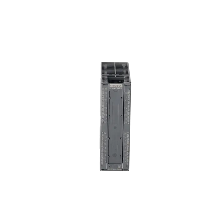
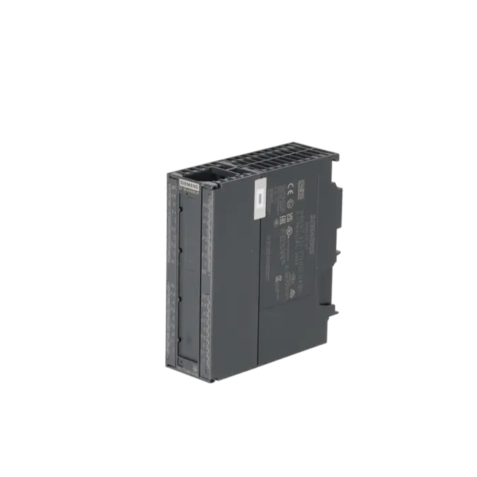
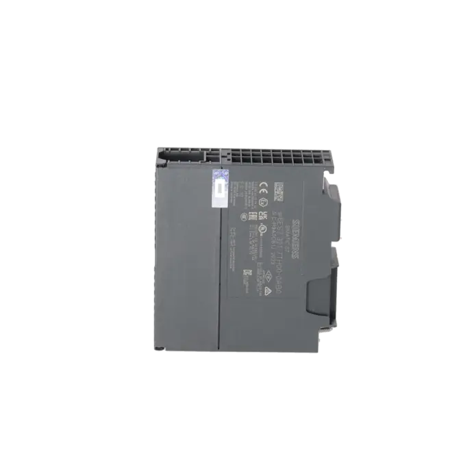
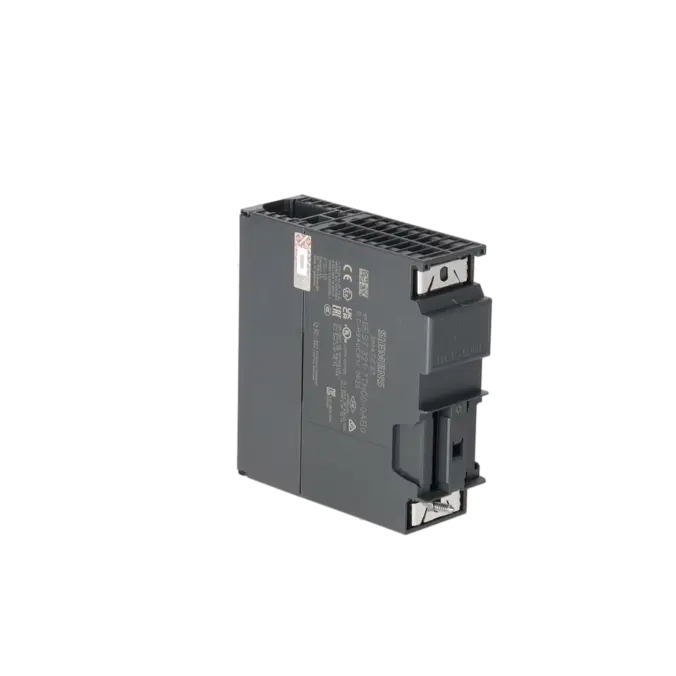
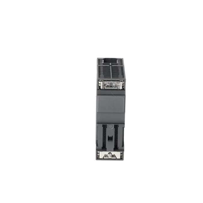

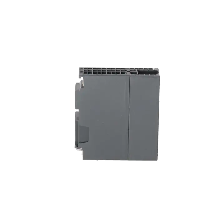
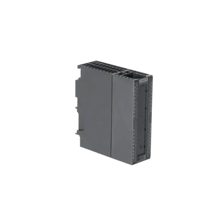

SIEMENS 6ES7321-7TH00-0AB0
-
SIEMENS | PLC Controls | Digital Input / Output Modules
- EICHLER-art.no.: K0118540
- EAN: 4025515066729
- UPC: 040892693010
Product description
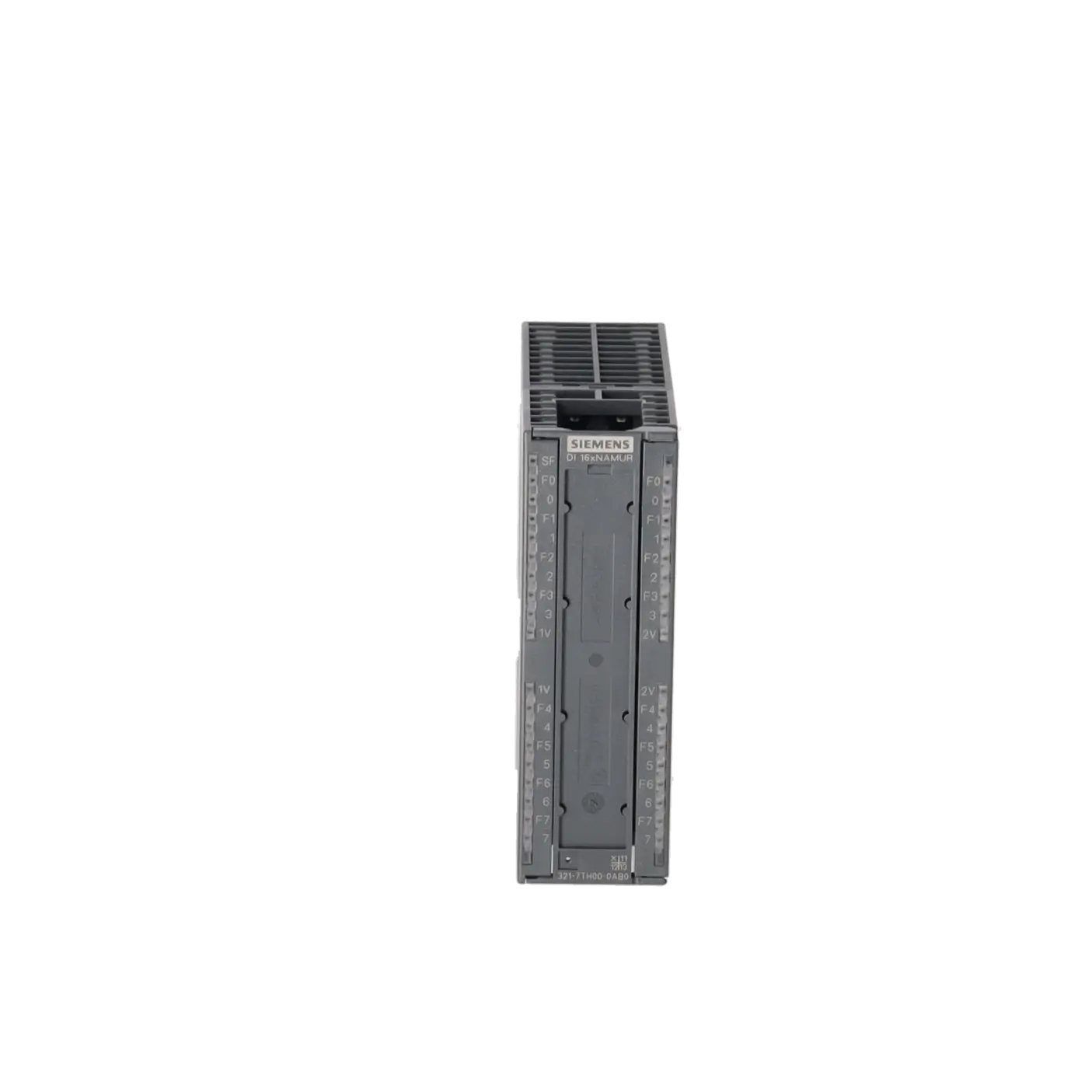
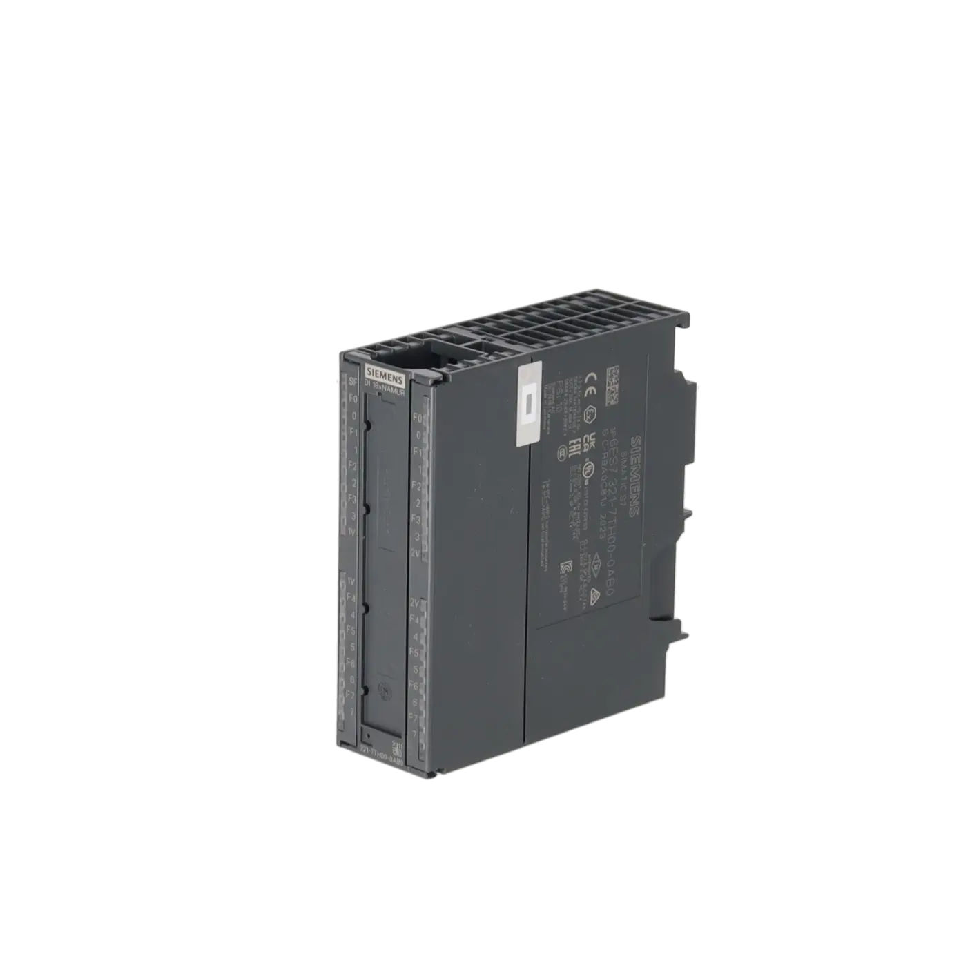
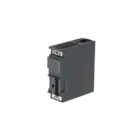
SIMATIC S7/PCS7 DIGITAL INPUT SM 321, 16 DI; 24 V DC, 1 X 40-POLE, DIAGNOSTICS-CAPABLE, FOR CONTACTS (WIRED/ NOT WIRED), NAMUR ENCODER, 3/4-WIRE BERO, WITH CHATTER MONITORING; PULSE EXTENSION, OPEN-CIRCUIT DETECTION INTERFACE MODULE IM 153-2 HF OR IM 153-
Services for SIEMENS 6ES7321-7TH00-0AB0
Repair
from 740,01 €
to 1.088,25 €
Replacement
Used
New
1.451,00 €
1.088,25 €
SIEMENS |
6ES7321-7TH00-0AB0 –
additional product information
| Delivery information | |||
|---|---|---|---|
| Export identifier | AL: N ECCN: EAR99H | ||
| Net weight | 0.385 | ||
| Quantity | 1 Stück | ||
| Packaging quantity | 1 | ||
| Additional product information | |||
|---|---|---|---|
| Product status | EOP: 2025-10-01 | ||
| EAN | 4025515066729 | ||
| UPC | 040892693010 | ||
| Static lot number | 85389091 | ||
| List indicator | STPCS7 | ||
| Product group | 4428 | ||
| Country of origin | DE | ||
| Compliance with the substance restrictions according to RoHS directive | Since: 20110414 | ||
| Product classifications | Version | Classification | |
|---|---|---|---|
| eClass | 4 | 27-24-03-04 | |
| eClass | 5.1 | 27-24-22-04 | |
| eClass | 6.0 | 27-24-22-04 | |
| ETIM | 3 | / | |
| ETIM | 4 | EC001419 | |
| ETIM | 5 | EC001419 | |
What is 6ES7321-7TH00-0AB0 and where is it used?
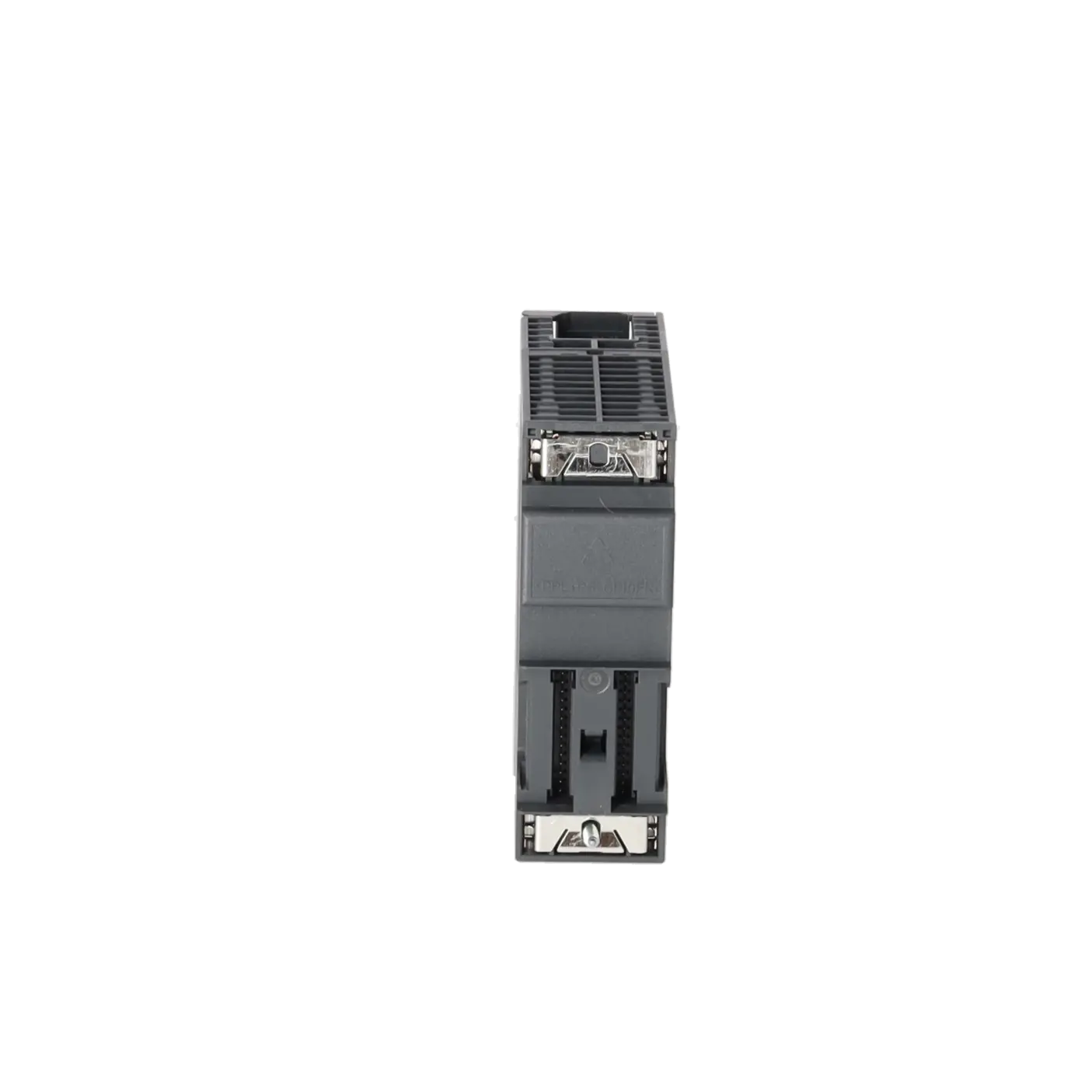
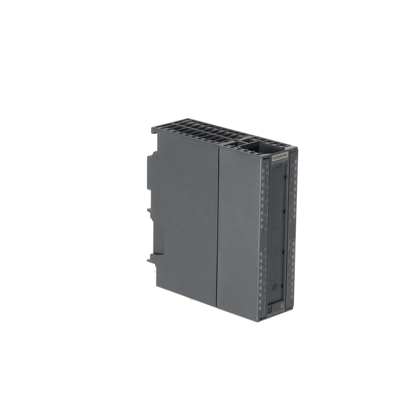
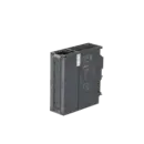
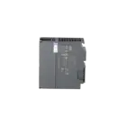
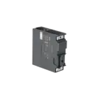
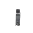
The 6ES7321-7TH00-0AB0 is a SIMATIC S7/PCS 7 SM 321 digital input module from Siemens with 16 digital 24 V DC inputs. It is designed for wired and unwired contacts, NAMUR sensors, and 3-wire/4-wire proximity switches, and provides additional diagnostic functions such as wire-break detection, contact bounce monitoring, and pulse extension. As a result, the module is particularly well suited to PCS 7 and ET 200M applications where signals must not only be detected but also evaluated for quality and reliability. Typical applications include limit level switches, limit positions, valve feedback signals, and other binary sensor signals in systems where effective diagnostics help reduce downtime and speed up troubleshooting.
Overview of the key technical specifications and what they mean
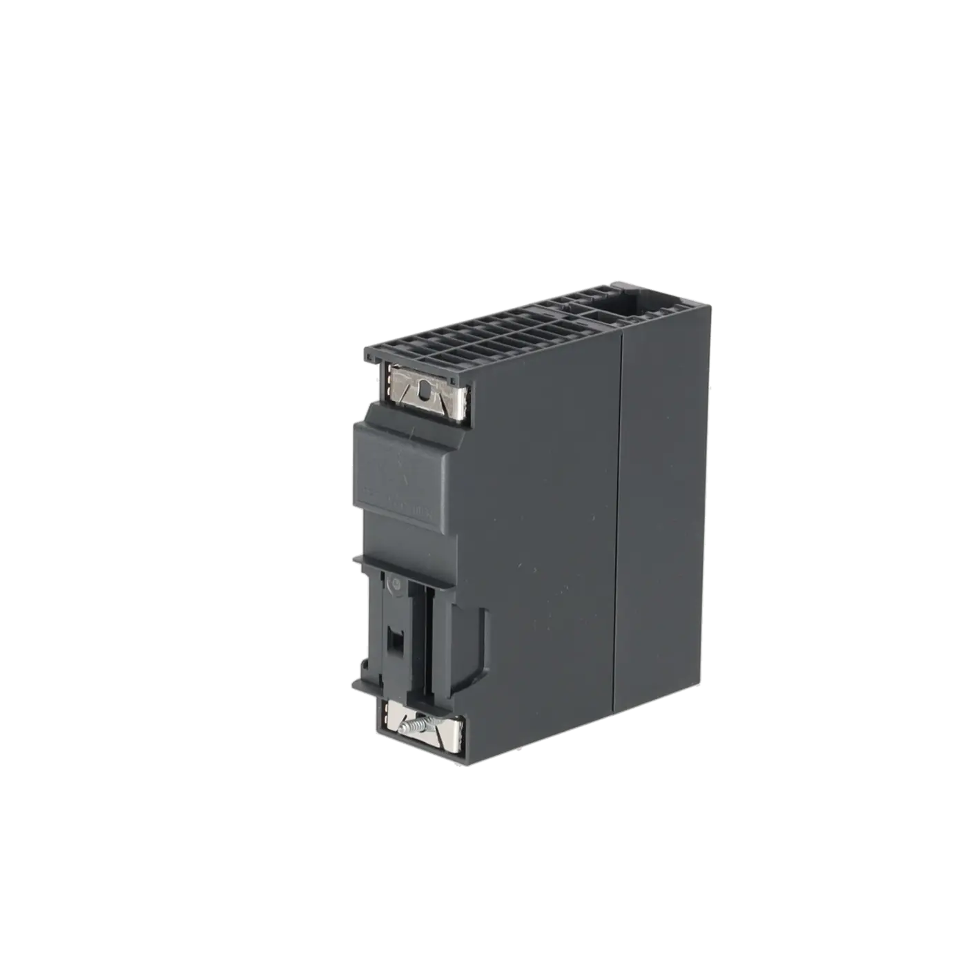
The module provides 16 digital inputs, requires a 24 V DC load supply, and uses a single 40-pin front connector. On the sensor side, it operates with evaluation voltages of 8.2 V and 18 V. Particularly important for maintenance personnel are the diagnostic-capable inputs, the input delay of 2.5 to 3.5 ms, the operating temperature range of 0 to 60 °C, the isolated channel structure in groups of eight, and the maximum shielded cable length of up to 400 m. In practical terms, this means that the module is designed for robust signal acquisition in industrial environments, supports typical NAMUR instrumentation, and provides valuable diagnostic information to both the PLC and the control system. This helps distinguish actual process conditions from fault-related signals more quickly.
Product status, life-cycle status, and obsolescence
From a procurement perspective, it is important to note that the EICHLER product page lists the module with EOP: 2025-10-01. Siemens also identifies the 6ES7321-7TH00-0AB0 as a spare part in its product references. This indicates that the module remains relevant for existing installations but is no longer considered one of the core products of the platform. No direct 1:1 replacement module could be clearly verified in the reviewed Siemens sources. For modernisation projects, however, Siemens documents adapter-based migration paths to 6ES7521-7TH00-0AB0 in the S7-1500 environment and to 6DL1131-6TH00-0PH1 in the ET 200SP HA environment. For operators, this means that continued operation remains possible, but the module should be included in medium-term obsolescence planning.
Available EICHLER services and their practical benefits
For this module, EICHLER offers repair, exchange, used, and new units. Repair is particularly relevant when the existing system is intended to continue operating unchanged and when addressing, wiring, and configuration should remain intact. EICHLER combines repair services with technical cleaning, preventive maintenance, comprehensive functional testing, and a minimum 24-month warranty. This is especially valuable for maintenance and purchasing departments when obsolescence is already becoming an issue but a complete retrofit is not yet economically justified. Exchange and used-unit solutions help minimise downtime in the short term, while new units are attractive when a planned spare part is required for critical stockholding or preventive replacement strategies.
| Attribute | Value |
|---|---|
| Supply voltage | |
| Load voltage L+ | |
| ● Rated value (DC) | 24 V |
| ● Reverse polarity protection | Yes |
| Input current | |
| from load voltage L+ (without load), max. | 100 mA |
| from backplane bus 5 V DC, max. | 100 mA |
| Encoder supply | |
| Number of outputs | 4 |
| Type of output voltage | 1Vs1/2Vs1: 18 V, 1Vs2/2Vs2: 8.2 V |
| Short-circuit protection | Yes; Electronic |
| additional (redundant) feed | No |
| Output current | |
| ● Rated value | 190 mA; at 18V: 190mA, at 8.2V: 60mA |
| ● permissible range, upper limit | Up to 60 degree: at 18V: 0 to 110mA, at 8.2V: 0 to 60mA; Up to 40 degree: at 18V: 0 to 190mA, at 8.2V: 0 to 60mA |
| Power loss | |
| Power loss, typ. | 11 W |
| Digital inputs | |
| Number of digital inputs | 16 |
| Input characteristic curve in accordance with IEC 61131, type 1 | No |
| Input characteristic curve in accordance with IEC 61131, type 2 | Yes |
| Number of simultaneously controllable inputs | |
| horizontal installation | |
| — up to 60 °C, max. | 16 |
| vertical installation | |
| — up to 40 °C, max. | 16 |
| Input voltage | |
| ● Type of input voltage | DC |
| ● Rated value (DC) | 8.2 V; 8.2V/18V |
| Input current | |
| ● for signal "0", min. | 0.35 mA |
| ● for signal "0", max. (permissible quiescent current) | 1.2 mA |
| ● for signal "1", typ. | 10 mA; for NAMUR: 2.1 to 7 mA, for 10k ohm/47k ohm contact: typical 10mA, for 4 wire BEROs: typical 10 mA |
| Input delay (for rated value of input voltage) | |
| for standard inputs | |
| — at "0" to "1", min. | 2.5 ms |
| — at "0" to "1", max. | 3.5 ms |
| — at "1" to "0", min. | 2.5 ms |
| — at "1" to "0", max. | 3.5 ms |
| Cable length | |
| ● shielded, max. | 400 m; max. 200m with 8.2 V sensor, max. 400m with 18 V sensor |
| ● unshielded, max. | Not permitted |
| Interrupts/diagnostics/status information | |
| Alarms | Yes |
| Diagnostics function | Yes |
| Alarms | |
| ● Diagnostic alarm | Yes |
| ● Hardware interrupt | Yes |
| Diagnoses | |
| ● Diagnostic information readable | Yes |
| ● Wire break | Yes |
| Diagnostics indication LED | |
| ● Group error SF (red) | Yes |
| ● Status indicator digital input (green) | Yes |
| ● Encoder supply Vs (green) | Yes |
| Potential separation | |
| Potential separation digital inputs | |
| ● between the channels | Yes |
| ● between the channels, in groups of | 8 |
| ● between the channels and backplane bus | Yes |
| Isolation | |
| Isolation tested with | 600 V DC |
| Ambient conditions | |
| Ambient temperature during operation | |
| ● min. | 0 °C |
| ● max. | 60 °C |
| Connection method | |
| required front connector | 1x 40-pin |
| Dimensions | |
| Width | 40 mm |
| Height | 125 mm |
| Depth | 120 mm |
| Fault description | Possible solution |
|---|---|
| Why does the 6ES7321-7TH00-0AB0 report a wire break even though the contact is connected? | First check the cable route between the module and the sensor, the sensor supply, and the contact wiring with a 10 kΩ or 47 kΩ resistor directly at the contact. Siemens lists typical causes such as an interrupted sensor cable, an interrupted supply, a broken bridging resistor, or a defective sensor. If a contact is operated without suitable wire-break monitoring, the parameterisation must also match the actual sensor type. |
| Why does the SF LED remain red, or why does one channel permanently show a fault? | The module reports short circuit, wire break, contact bounce fault, missing load voltage L+, or sensor supply failure on a channel-specific basis. Therefore, check the L+ supply, sensor wiring, possible short circuits between the sensor cable and sensor supply, and whether group diagnostics are enabled. If the fault remains after the wiring has been corrected, a defective sensor or module fault should be considered. |
| Why is the input signal visible in the PLC but marked as invalid? | In addition to the input signal, this module provides a separate value status. Siemens describes that the value status is stored in the process image after the input word and indicates whether the signal is valid. Invalid signals can occur due to sensor or voltage faults, wire-break testing, short circuits in the sensor cable, contact bounce monitoring, or changeover-contact diagnostics. For troubleshooting, it is therefore not sufficient to evaluate only the input bit. |
| Why does a changeover contact generate a diagnostic alarm? | When a sensor is evaluated as a changeover contact, the module expects the changeover between the normally closed and normally open contacts to occur within 300 ms. If this time is exceeded or the mechanical coupling is unreliable, the module marks the normally open channel as invalid and generates a diagnostic interrupt. In this case, check the channel pairing, mechanical coupling, contact play, and the wiring of both associated channels. |
| Why do contact bounce faults or unstable status changes occur? | The contact bounce monitoring detects unusually frequent switching between 0 and 1. Typical causes include bouncing contacts, unstable sensors, or interference on the cable. Siemens describes that when a contact bounce fault occurs, the current signal state is still transferred to the process image, but the value status is set to invalid. Check the sensor condition, shielding, grounding, and the configured input delay. |
What is the difference between a standard 24 V DI module and the 6ES7321-7TH00-0AB0?
The 6ES7321-7TH00-0AB0 is more than a standard 24 V digital input module. It is designed for NAMUR sensors, monitored and unmonitored contacts, and 3-wire/4-wire proximity switches, and extends basic signal acquisition with wire-break detection, contact bounce monitoring, pulse extension, and a value status for evaluating signal validity. This makes it particularly suitable for process-oriented applications where simple 0/1 detection is not sufficient and diagnostic information needs to be available directly within the control or process control system.
Which front connector is required for the 6ES7321-7TH00-0AB0?
The module requires one 40-pin front connector. This is important for purchasing and maintenance because, when replacing used or repaired modules, it is often missing connection accessories rather than the electronics themselves that delay recommissioning. When sourcing a replacement, the module, front connector, and existing wiring concept should therefore always be checked together.
Is the 6ES7321-7TH00-0AB0 discontinued or still available?
The evaluated product information lists the module with EOP: 2025-10-01, and Siemens classifies it as a spare part. At the same time, it remains available through EICHLER via repair, exchange, used, and new procurement options. For operators, this means the module is no longer part of the latest product generation, but it remains relevant in the context of spare parts supply and service support.
Is there a compatible replacement or migration path for the 6ES7321-7TH00-0AB0?
No single product was clearly identified in the reviewed Siemens documentation as a direct successor. However, Siemens documents migration paths using adapters. In migration guides, the module is mapped to 6ES7521-7TH00-0AB0 in the S7-1500 environment and to 6DL1131-6TH00-0PH1 in the ET 200SP HA environment. This is particularly relevant for retrofit projects where existing wiring and system availability must be considered. This assessment is derived from Siemens migration and adapter documentation and should not be interpreted as the designation of a direct 1:1 successor.
Can repair be more economical than purchasing a new module?
Yes, particularly when the existing PCS 7 or ET 200M structure is to remain unchanged, when the module must be returned to service quickly, or when obsolescence is already becoming a concern but a retrofit project has not yet been approved. EICHLER's repair service includes technical cleaning, preventive maintenance, comprehensive functional testing, and a minimum 24-month warranty. For many operators, this is more economical than carrying out an unplanned migration under time pressure.
Which sensors can be connected to the 6ES7321-7TH00-0AB0?
The module is designed for NAMUR sensors, monitored and unmonitored contacts, and 3-wire/4-wire proximity switches. Siemens documentation also describes contact monitoring concepts using 10 kΩ and 47 kΩ resistors for diagnostic purposes. This is especially important when wire-break monitoring or clearly defined contact states are required. Therefore, selecting the correct module depends not only on the article number but also on the actual sensor type and the desired diagnostic functionality.