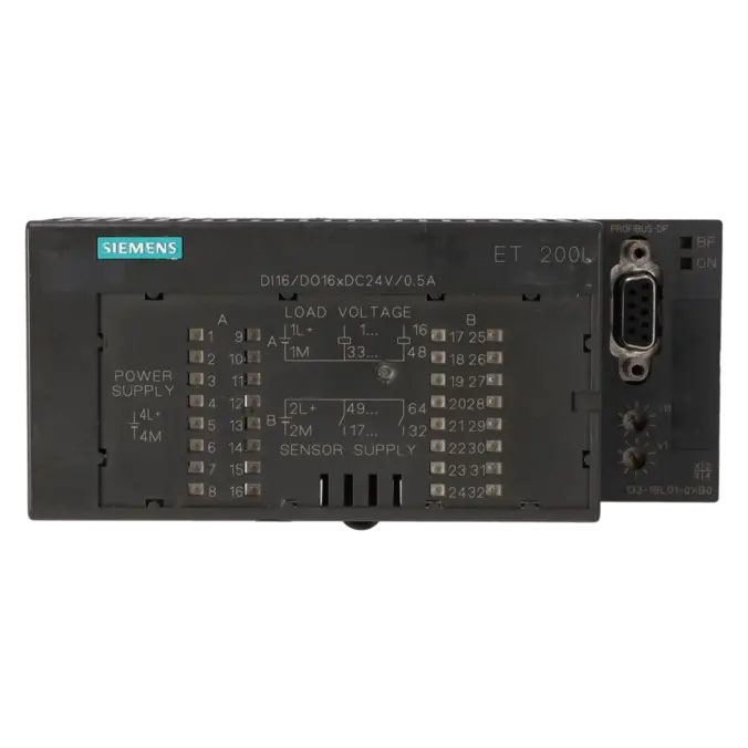
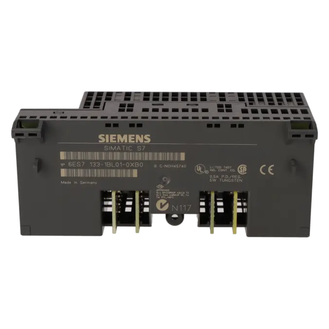
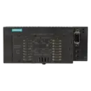
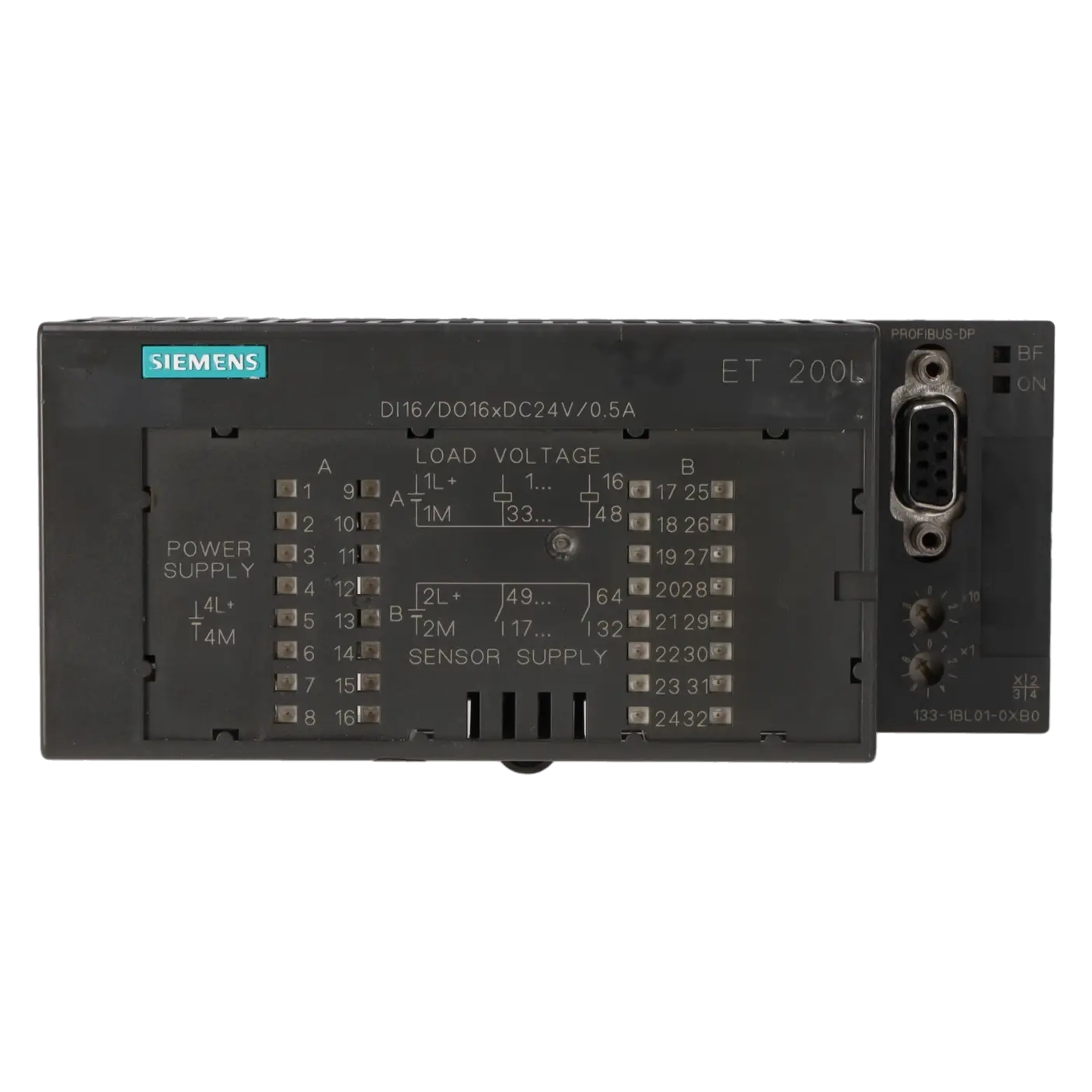
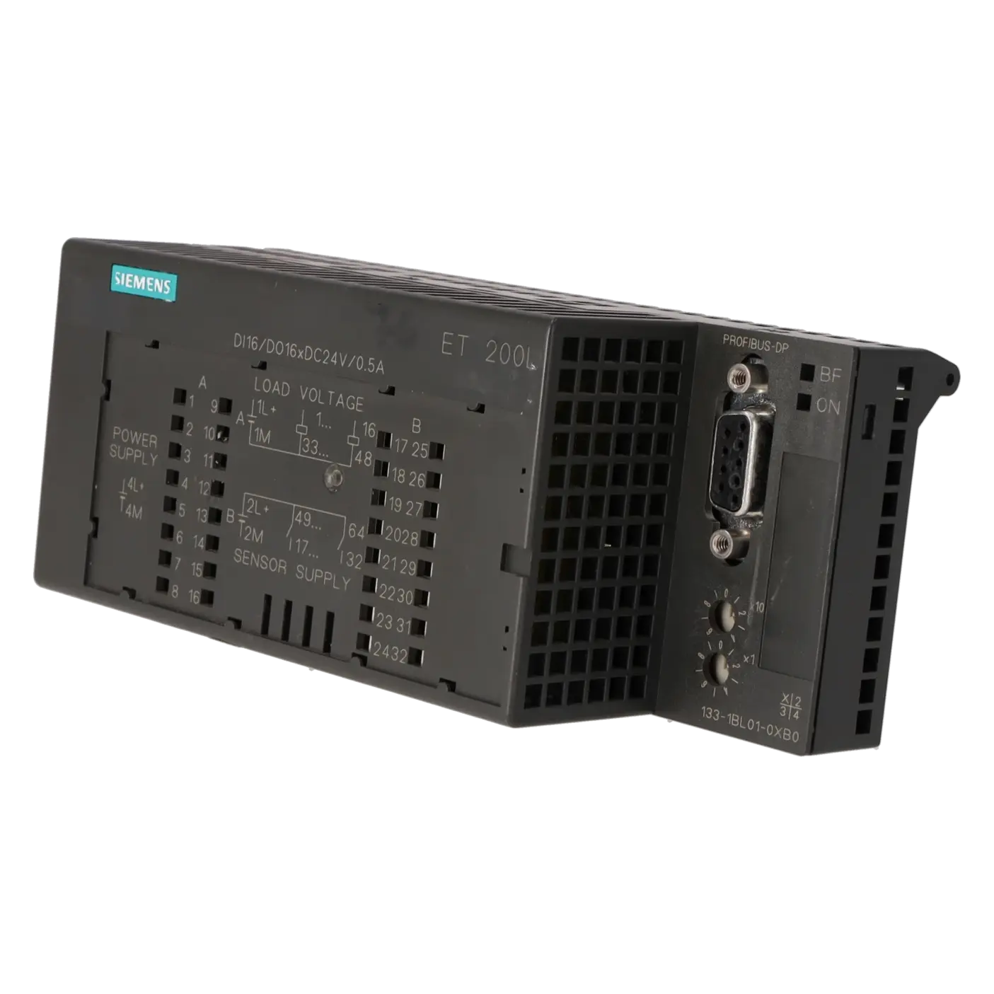
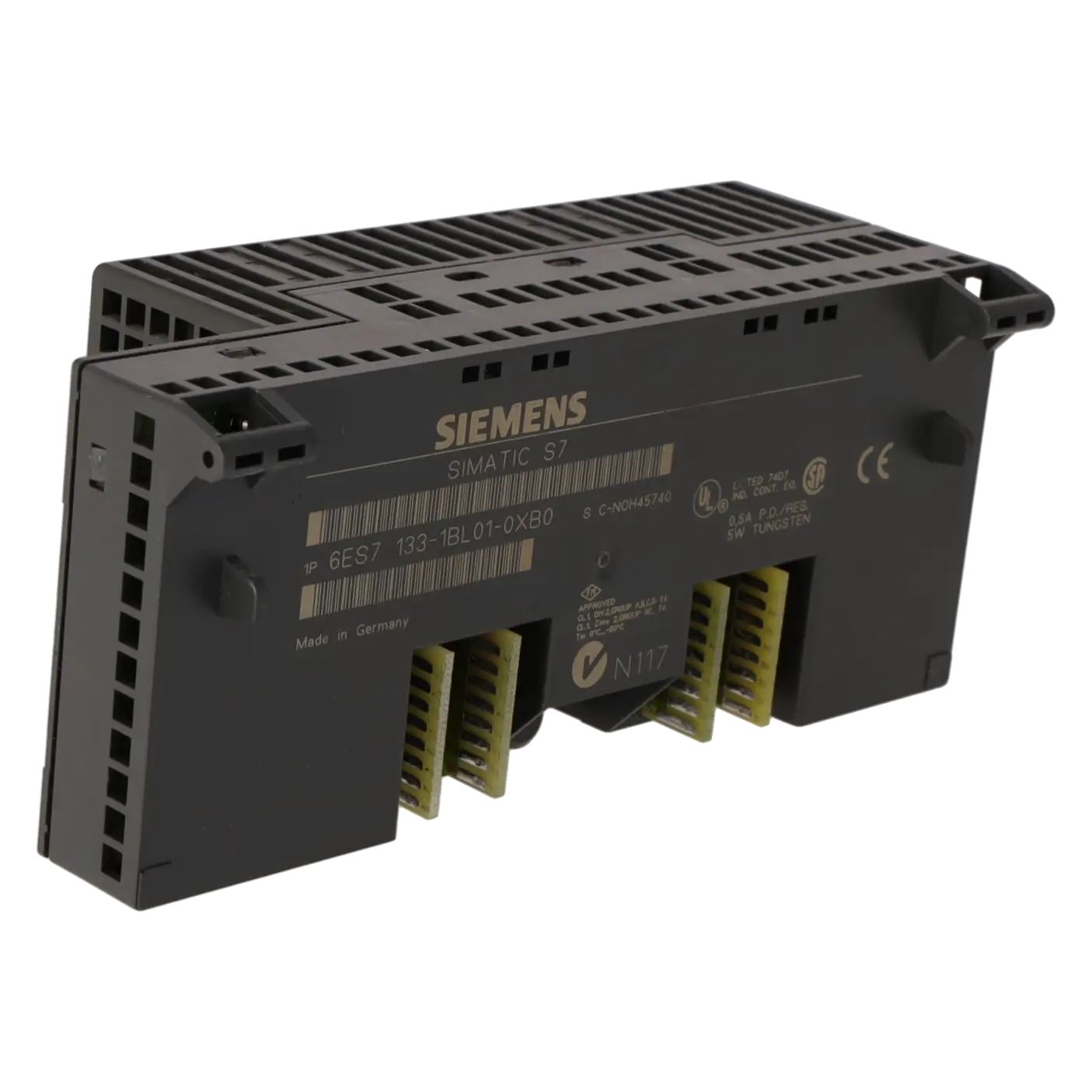
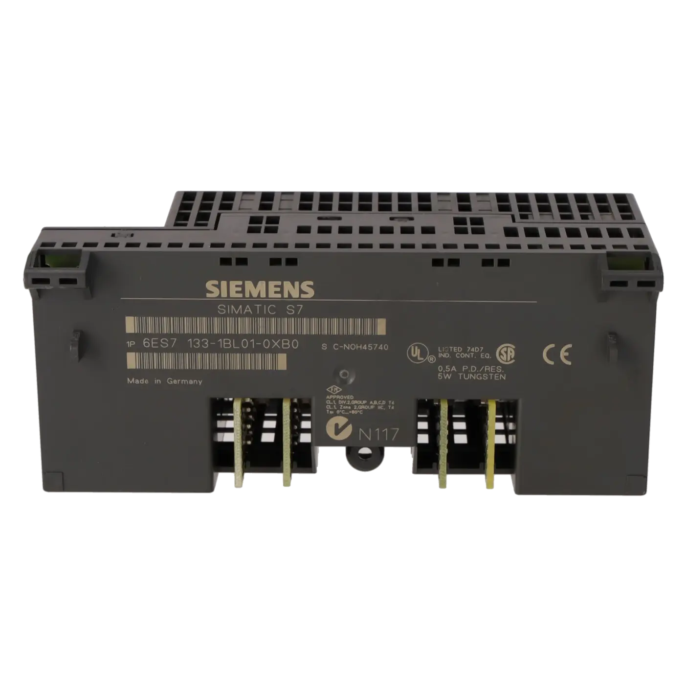
| Usable terminal block |
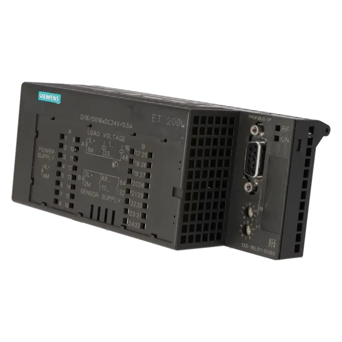
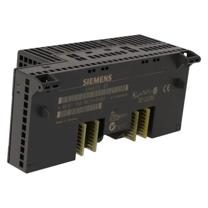
TB 32L |
| Supply voltage |
|
| Rated value (DC) |
24 V |
| Reverse polarity protection |
Yes |
| Mains buffering |
|
| ● Mains/voltage failure stored energy time |
20 ms |
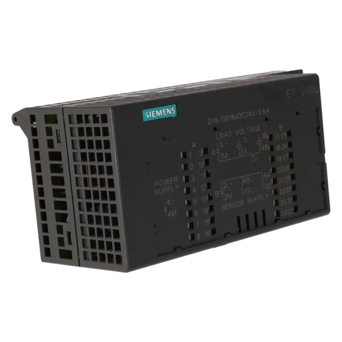
| Load voltage L+ |
|
| ● Rated value (DC) |
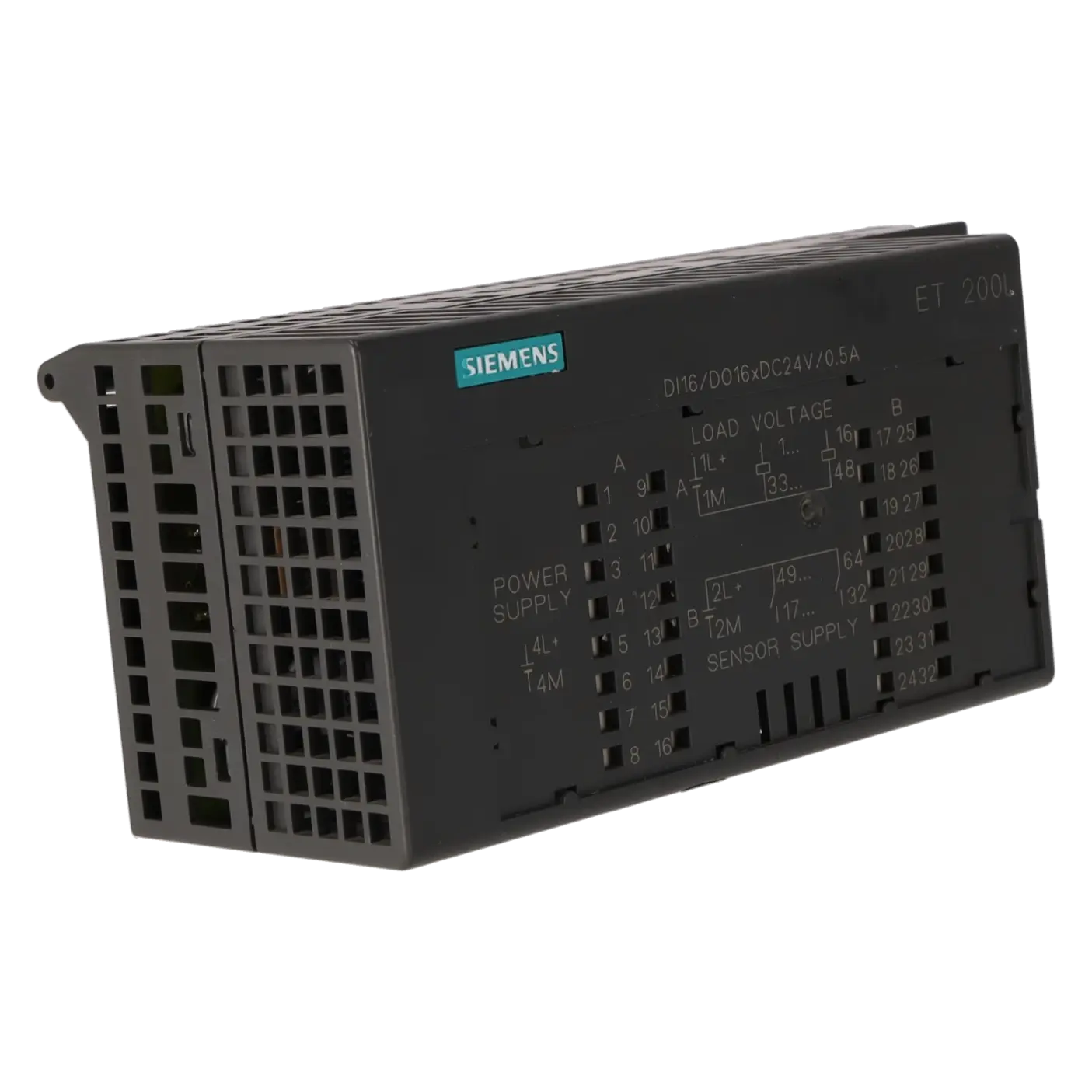
24 V; 1L+, 2L+, 3L+ |
| Input current |
|
| from supply voltage L+, max. |
70 mA; L4+ / L5+ |
| from load voltage L+ (without load), max. |
50 mA |
| Power loss |
|
| Power loss, typ. |
5 W |
| Digital inputs |
|
| Number of digital inputs |
16 |
| Input characteristic curve in accordance with IEC 61131, type 1 |
Yes |
| Number of simultaneously controllable inputs |
|
| ● Number of simultaneously controllable inputs |
16 |
| Input voltage |
|
| ● Rated value (DC) |
24 V |
| ● for signal "0" |
-30 to +5 V |
| ● for signal "1" |
13 to 30V |
| Input current |
|
| ● for signal "0", max. (permissible quiescent current) |
1.5 mA |
| ● for signal "1", typ. |
5 mA |
| Input delay (for rated value of input voltage) |
|
| for standard inputs |
|
| — at "0" to "1", min. |
2 ms |
| — at "0" to "1", max. |
4.5 ms |
| — at "1" to "0", min. |
2 ms |
| — at "1" to "0", max. |
4.5 ms |
| Cable length |
|
| ● shielded, max. |
1 000 m |
| ● unshielded, max. |
600 m |
| Digital outputs |
|
| Number of digital outputs |
16 |
| Short-circuit protection |
Yes |
| ● Response threshold, typ. |
0.7 A |
| Limitation of inductive shutdown voltage to |
Typ. (L1+ or L2+ / L3+) -55 V |
| Controlling a digital input |
Yes |
| Switching capacity of the outputs |
|
| ● on lamp load, max. |
5 W |
| Load resistance range |
|
| ● lower limit |
41 Ω |
| ● upper limit |
28 kΩ |
| Output voltage |
|
| ● Rated value (DC) |
24 V |
| ● for signal "1", min. |
Ua - 3 V |
| Output current |
|
| ● for signal "1" permissible range, min. |
1 mA |
| ● for signal "1" permissible range, max. |
0.5 A |
| ● for signal "0" residual current, max. |
1 mA |
| Output delay with resistive load |
|
| ● "0" to "1", max. |
50 µs |
| ● "1" to "0", max. |
200 µs |
| Parallel switching of two outputs |
|
| ● for uprating |
No |
| ● for redundant control of a load |
Yes |
| Switching frequency |
|
| ● with resistive load, max. |
100 Hz |
| ● with inductive load, max. |
0.5 Hz |
| ● on lamp load, max. |
8 Hz |
| Total current of the outputs (per group) |
|
| horizontal installation |
|
| — up to 30 °C, max. |
4 A |
| — up to 40 °C, max. |
3 A |
| — up to 60 °C, max. |
2 A |
| all other mounting positions |
|
| — up to 40 °C, max. |
2 A |
| Cable length |
|
| ● shielded, max. |
1 000 m |
| ● unshielded, max. |
600 m |
| Encoder |
|
| Connectable encoders |
|
| ● 2-wire sensor |
Yes |
| Interfaces |
|
| Transmission rate, max. |
1.5 Mbit/s |
| Protocols |
|
| Bus protocol/transmission protocol |
PROFIBUS DP |
| PROFIBUS DP |
|
| Services |
|
| — SYNC capability |
Yes |
| — FREEZE capability |
Yes |
| — Direct data exchange (slave-to-slave communication) |
Yes; Transmitter (for digital outputs and hybrid modules ET 200L: not for L-SC or IM-SC) |
| Interrupts/diagnostics/status information |
|
| Alarms |
No |
| Diagnostics function |
Yes |
| Diagnostics indication LED |
|
| ● Bus fault BF (red) |
Yes |
| ● Status indicator digital input (green) |
Yes |
| ● Status indicator digital output (green) |
Yes |
| ● Monitoring 24 V voltage supply ON (green) |
Yes |
| Potential separation |
|
| between PROFIBUS DP and all other circuit components |
Yes |
| Potential separation digital inputs |
|
| ● between the channels |
No |
| ● between the channels and PROFIBUS DP |
Yes |
| Potential separation digital outputs |
|
| ● between the channels |
No |
| ● between the channels and PROFIBUS DP |
Yes |
| Isolation |
|
| Isolation tested with |
500 V DC |
| Degree and class of protection |
|
| IP degree of protection |
IP20 |
| Ambient conditions |
|
| Ambient temperature during operation |
|
| ● horizontal installation, min. |
0 °C |
| ● horizontal installation, max. |
60 °C; 40°C for other mountings |
| Air pressure acc. to IEC 60068-2-13 |
|
| ● permissible range, lower limit |
795 hPa |
| ● permissible range, upper limit |
1 080 hPa |
| Relative humidity |
|
| ● Operation, min. |
5 % |
| ● Operation, max. |
95 %; RH class 2 in accordance with IEC 1131-2 |
| Vibrations |
|
| ● Operation, tested according to IEC 60068-2-6 |
Yes; IEC 68, Part 2-6; 10 to 57 Hz; (constant amplitude 0.075 mm); 57 to 150 Hz; (constant acceleration 1 g) |
| Shock testing |
|
| ● tested according to IEC 60068-2-27 |
Yes; IEC 68, Part 2-27; half-sine, 15 g, 11 ms |
| connection method |
|
| Design of electrical connection for the inputs and outputs |
Screw-type and spring-loaded terminals, permanent wiring; standard: 2-wire connection, optional: 3 and 4-wire connection |
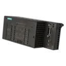
| Dimensions |
|
| Width |
145 mm |
| Height |
60 mm |
| Depth |
60.5 mm |
| Weights |
|
| Weight, approx. |
130 g |