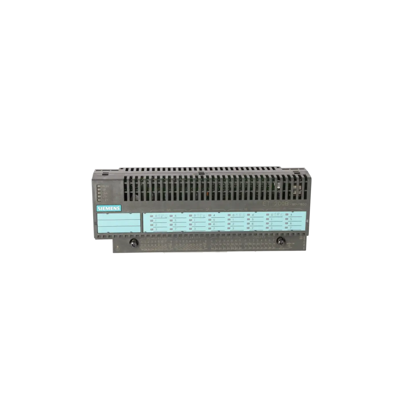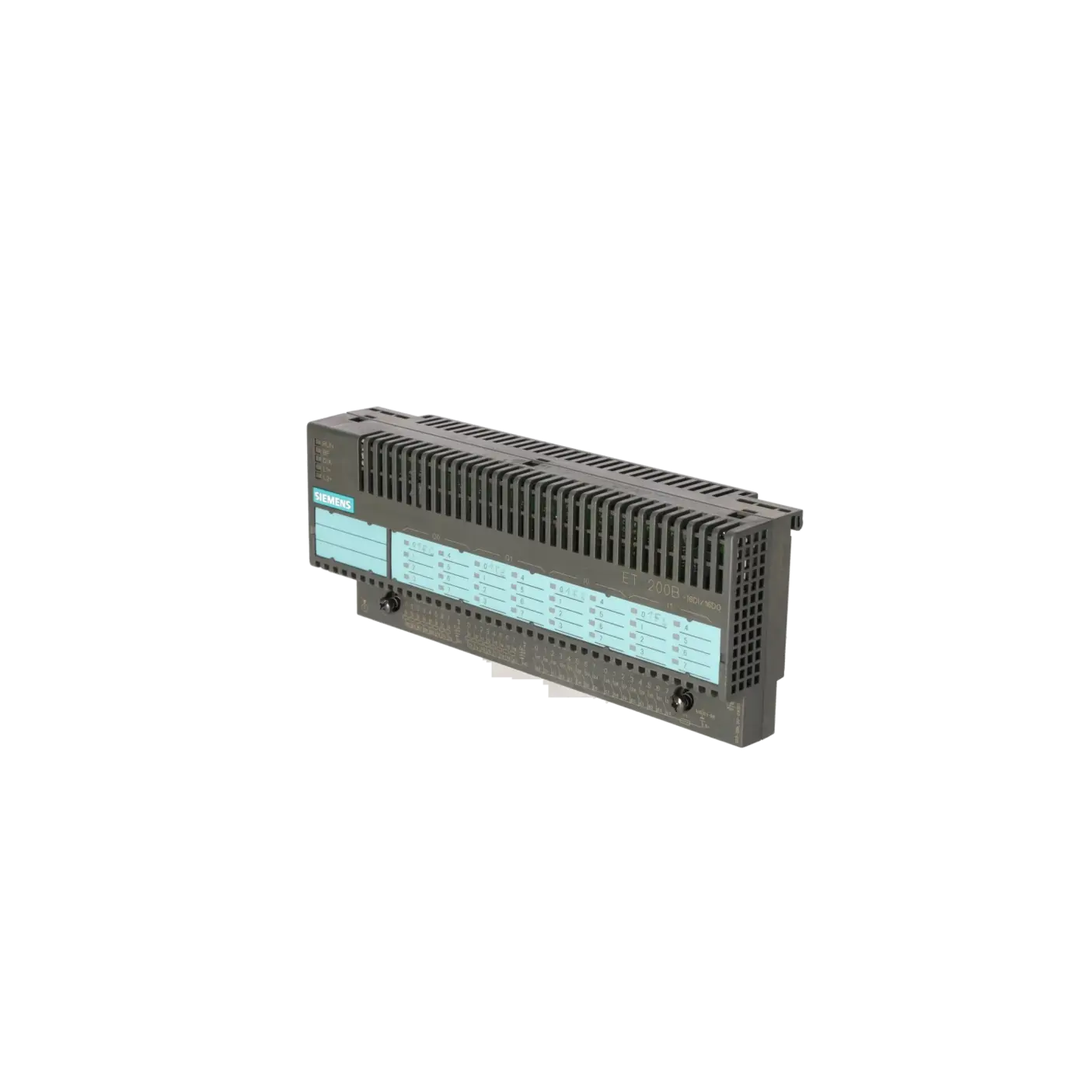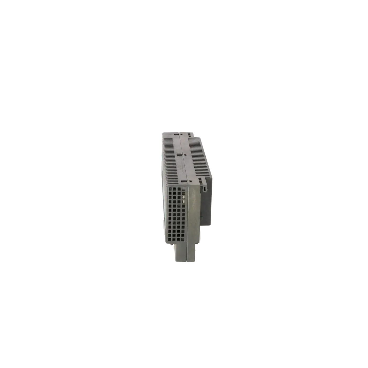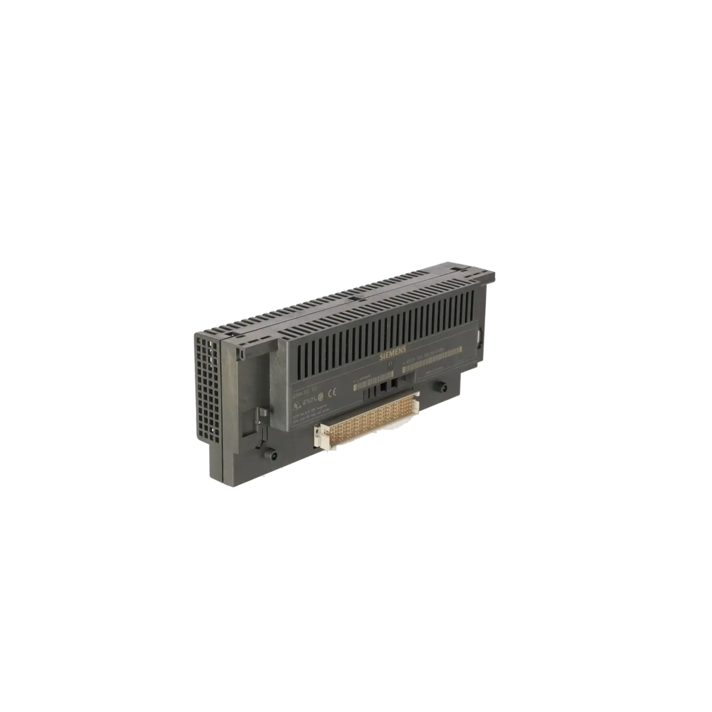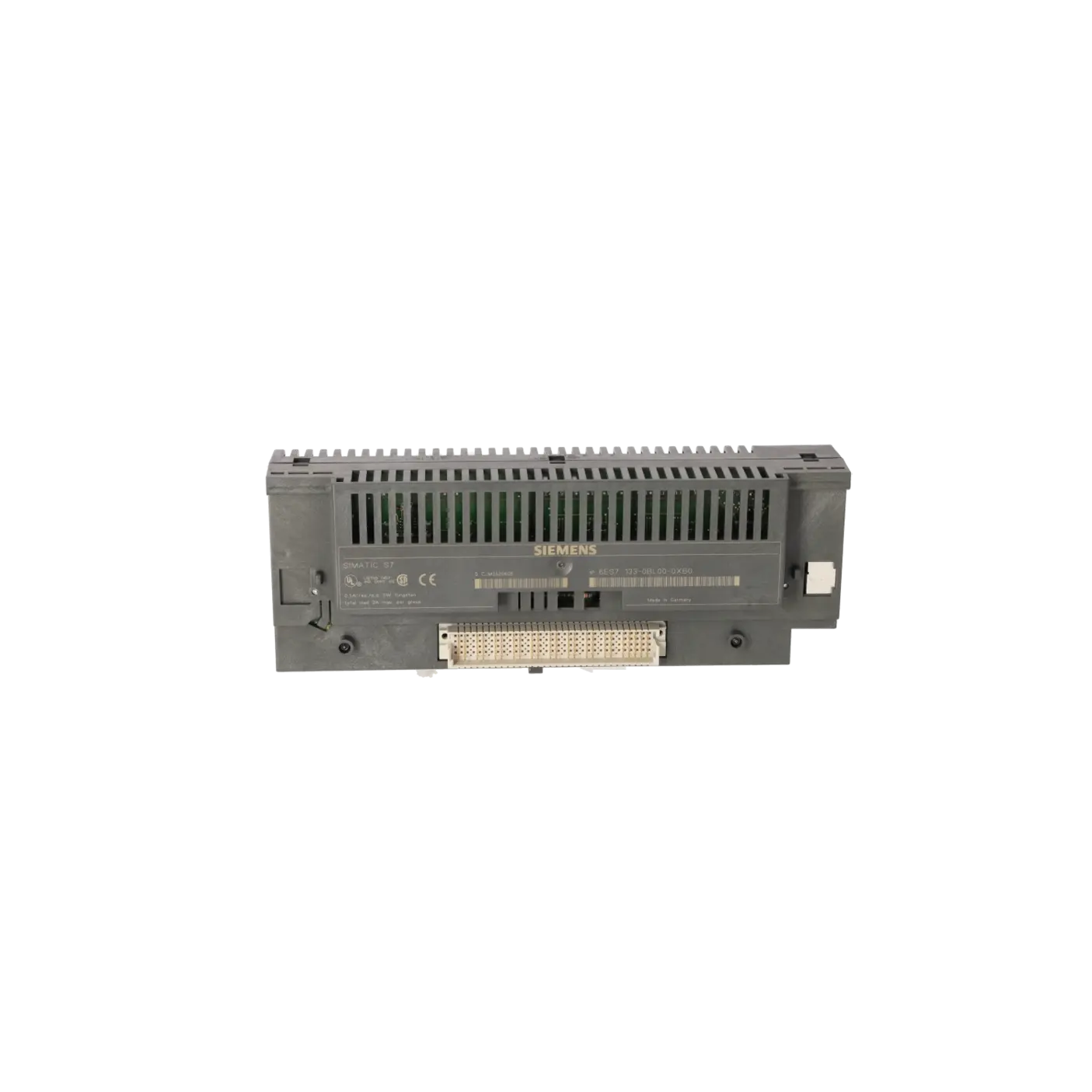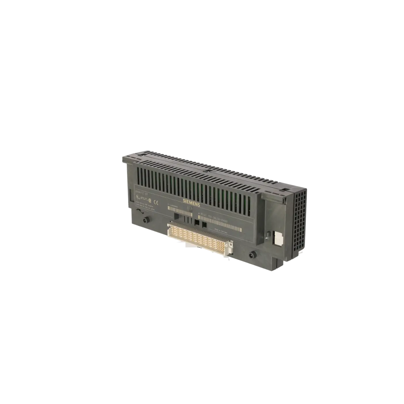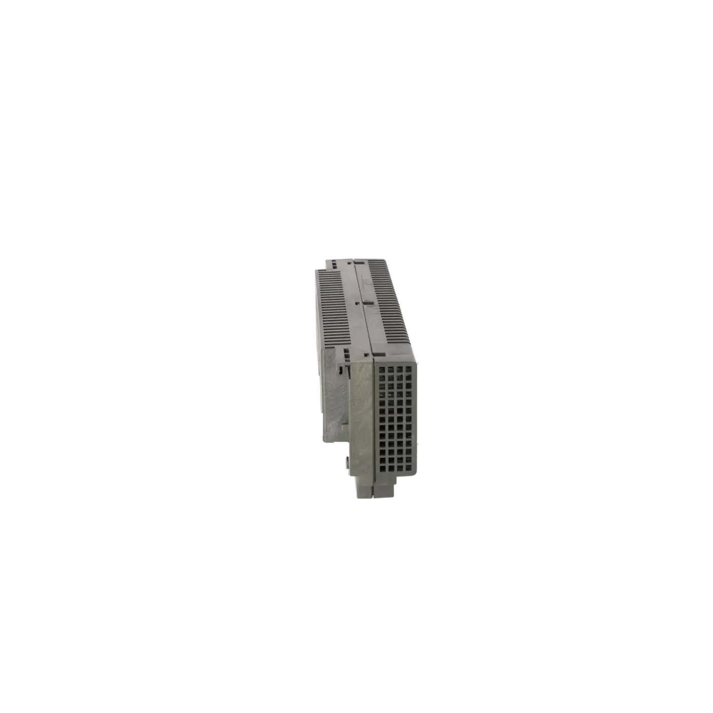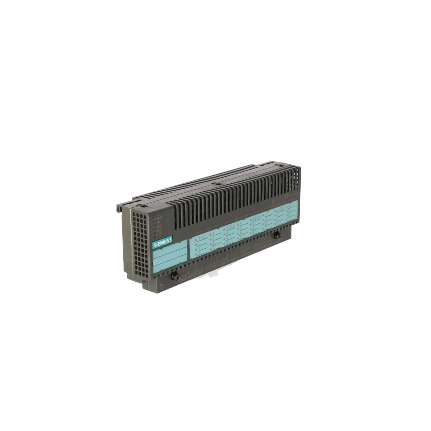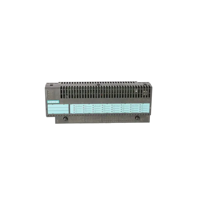
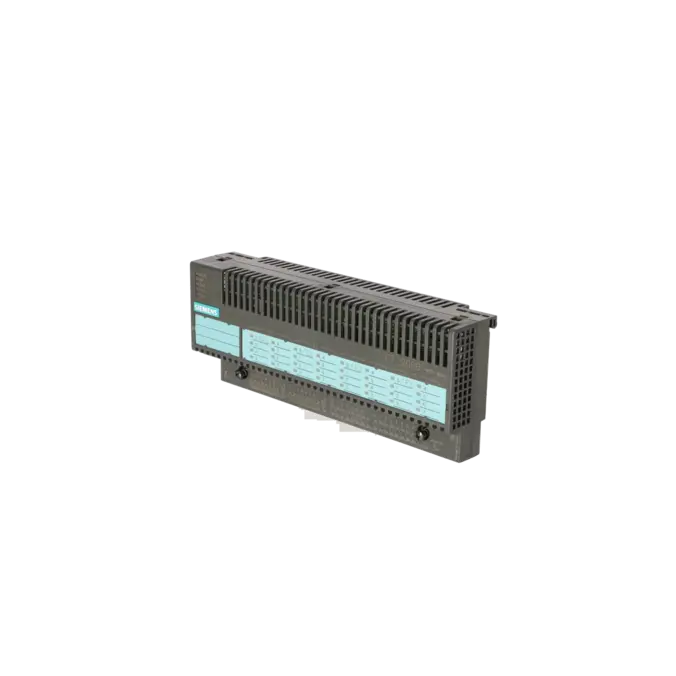
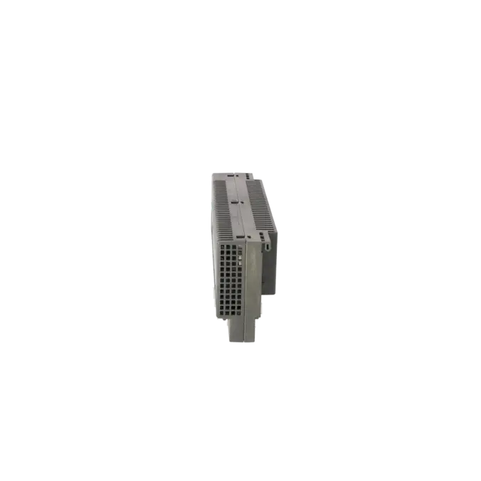
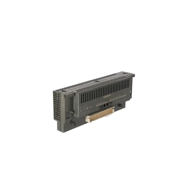
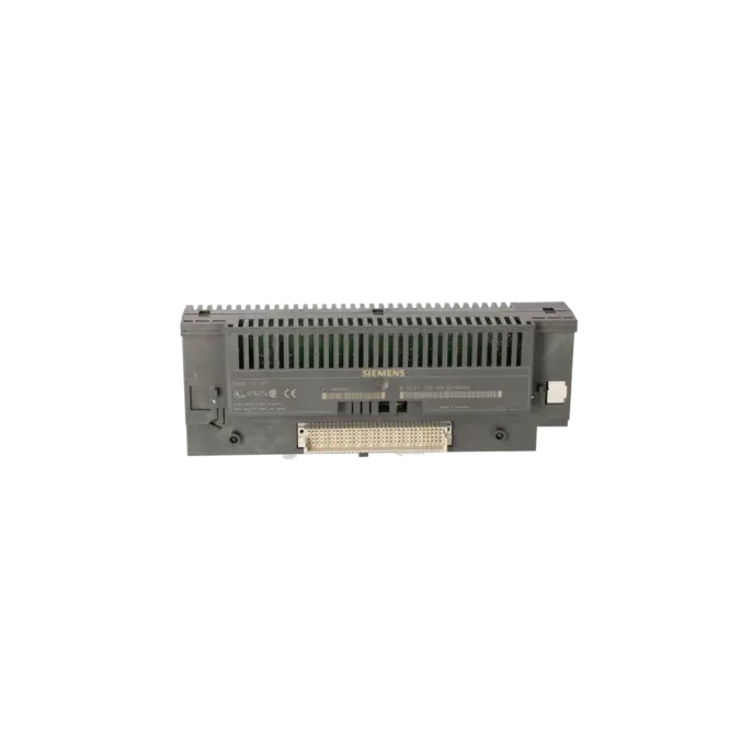
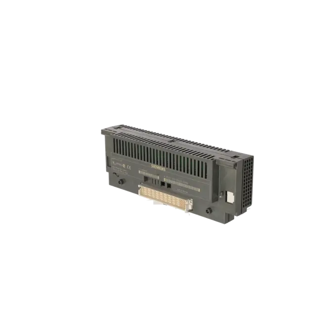
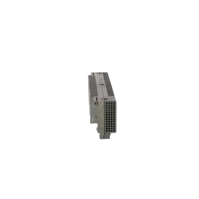
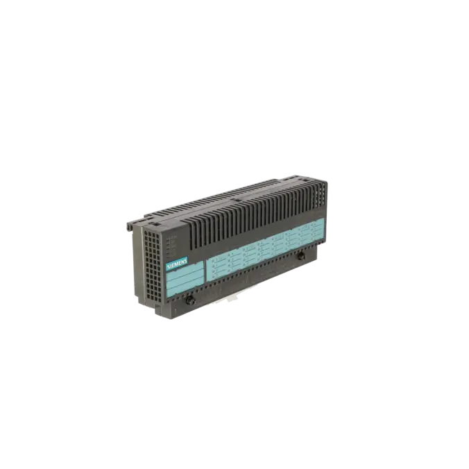
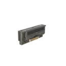
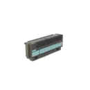
SIEMENS 6ES7133-0BL00-0XB0
- EICHLER-art.no.: K0118095
- EAN: 4025515058304
Product description
SIMATIC DP, ELECTRONIC MODULE DIGITAL, FOR ET 200B, W=235MM, 16DI 24V DC, 16DO 24V DC/0.,5A STANDARD
Services for SIEMENS 6ES7133-0BL00-0XB0
Repair
from 585,87 €
to 1.054,57 €
Replacement
948,60 €
901,17 €
Used
1.054,00 €
1.001,30 €
New
SIEMENS |
6ES7133-0BL00-0XB0 –
additional product information
| Delivery information | |||
|---|---|---|---|
| Export identifier | AL: ECCN: | ||
| Net weight | 0.329 | ||
| Quantity | 1 Stück | ||
| Packaging quantity | 1 | ||
| Additional product information | |||
|---|---|---|---|
| Product status | EOP: 2006-10-01 | ||
| EAN | 4025515058304 | ||
| UPC | / | ||
| Static lot number | 85389091 | ||
| List indicator | / | ||
| Product group | 4467 | ||
| Country of origin | DE | ||
| Compliance with the substance restrictions according to RoHS directive | Since: / | ||
| Product classifications | Version | Classification | |
|---|---|---|---|
| eClass | 4 | / | |
| eClass | 5.1 | / | |
| eClass | 6.0 | / | |
| ETIM | 3 | / | |
| ETIM | 4 | / | |
| ETIM | 5 | / | |
What is 6ES7133-0BL00-0XB0 and where is it used?
The 6ES7133-0BL00-0XB0 is a digital electronics assembly for the decentralised ET 200B I/O system from Siemens. The assembly operates as a PROFIBUS DP slave and combines 16 digital inputs with 16 digital outputs in a compact design. It is typically used in legacy systems where sensors and actuators need to be connected in a decentralised manner but where installation space is limited. Siemens describes the ET 200B family as a compact I/O station for applications with shallow installation depth and a relatively modest number of signals. For maintenance personnel, the article number is particularly relevant when a targeted 1:1 replacement, a repair or the continued support of existing PROFIBUS systems is required.
Overview of the most important technical data and what it means
The assembly processes 24 V DC signals on both the input and output sides and requires a supply via L1+, L2+ and L5+. The permissible voltage range is 18.5 to 30.2 V DC. The 16 inputs switch to signal “1” within a range of 13 to 30 V, while the 16 outputs provide up to 0.5 A per channel. The outputs are organised into groups of 8, with a maximum permissible load of 2 A per group. The input delay is a maximum of 3 ms, and communication takes place via PROFIBUS DP at speeds of up to 12 Mbit/s. In practice, this means that the assembly is well suited to conventional 24 V switching signals, valves, relays and simple actuators, but it requires proper load distribution across the output groups and a stable field power supply.
Product status, life cycle status and obsolescence status
For the 6ES7133-0BL00-0XB0, the shop lists a product status of EOP dated 2006-10-01. Siemens also classified the ET 200B system as a Mature Product from 1 October 2005 and announced the discontinuation of all ET 200B components by 30 September 2015. On the Siemens product page, the article number is listed as discontinued without a replacement product. Therefore, no verified 1:1 successor is apparent. For functional migration, however, Siemens refers to ET 200SP as the successor platform; in migration documentation, Siemens generally recommends ET 200SP or ET 200MP for modernisation projects. For operators of existing systems, this means that procurement, repair and inventory management remain key considerations for ET 200B installations.
Available EICHLER services and when they are relevant in practice
For this assembly, the key procurement options are repair, exchange, used assemblies and new equipment enquiries. Repair is particularly beneficial when the existing ET 200B structure is to remain unchanged and breakdown costs need to be reduced more quickly than would be possible through a complete migration. EICHLER specifies a turnaround time of 2 to 5 days and includes technical cleaning, preventive maintenance, functional testing and a minimum 24-month warranty. Exchange units and used assemblies are particularly attractive when a system must be returned to operation at short notice; these options are listed in the shop with lead times of 1 to 3 days. Especially for discontinued ET 200B assemblies, these services help maintain supply security despite obsolescence and make migration projects easier to plan.
| Attribute | Value |
|---|---|
| Usable terminal block | TB2/DC, TB2-4/DC, TB4/DC, TB4-4/DC |
| Supply voltage | |
| Rated value (DC) | 24 V; L1+, L2+, L5+; value at t < 0.5 s: 35 V |
| permissible range, lower limit (DC) | 18.5 V |
| permissible range, upper limit (DC) | 30.2 V |
| Input current | |
| Current consumption, typ. | 85 mA; From L5+; logic |
| Current consumption, max. | 1 000 mA; from L5+; sensor |
| I²t | 0.05 A²·s; with starting current inrush |
| Power loss | |
| Power loss, max. | 5.5 W |
| Digital inputs | |
| Number of digital inputs | 16 |
| Input voltage | |
| ● Rated value (DC) | 24 V |
| ● for signal "0" | -30 to +5 V |
| ● for signal "1" | 13 to 30V |
| Input current | |
| ● for signal "1", typ. | 4 mA; At 24 V min. 2 mA |
| Input delay (for rated value of input voltage) | |
| for standard inputs | |
| — at "0" to "1", max. | 3 ms |
| Cable length | |
| ● unshielded, max. | 100 m |
| Digital outputs | |
| Number of digital outputs | 16 |
| Short-circuit protection | Yes; Electronic |
| Limitation of inductive shutdown voltage to | typ. (L1+, L2+) -55 V |
| Controlling a digital input | Yes |
| Switching capacity of the outputs | |
| ● on lamp load, max. | 5 W |
| Output voltage | |
| ● Rated value (DC) | 24 V |
| ● for signal "0", max. | 2 V; idling |
| ● for signal "1", min. | UE -3 V |
| Output current | |
| ● for signal "1" permissible range, max. | 0.5 A; in groups of 8, each group 8x 0.5 A |
| ● for signal "0" residual current, max. | 1 mA |
| Output delay with resistive load | |
| ● "0" to "1", max. | 20 µs |
| ● "1" to "0", max. | 0.5 ms |
| Switching frequency | |
| ● with resistive load, max. | 1 000 Hz |
| ● with inductive load, max. | 0.5 Hz |
| ● on lamp load, max. | 8 Hz |
| Total current of the outputs (per group) | |
| all mounting positions | |
| — up to 60 °C, max. | 2 A |
| Cable length | |
| ● unshielded, max. | 100 m |
| Encoder | |
| Connectable encoders | |
| ● 2-wire sensor | Yes |
| — permissible quiescent current (2-wire sensor), max. | 1.5 mA |
| Interfaces | |
| PROFIBUS DP | |
| ● Transmission rate, max. | 12 Mbit/s |
| Protocols | |
| Bus protocol/transmission protocol | PROFIBUS DP |
| PROFIBUS DP | |
| Services | |
| — SYNC capability | Yes |
| — FREEZE capability | Yes |
| Interrupts/diagnostics/status information | |
| Diagnostics indication LED | |
| ● RUN LED | Yes |
| ● Bus fault BF (red) | Yes |
| ● Status indicator digital input (green) | Yes |
| ● Status indicator digital output (green) | Yes |
| Potential separation | |
| between electronic block and PROFIBUS DP | Yes |
| Potential separation digital inputs | |
| ● Potential separation digital inputs | No |
| Potential separation digital outputs | |
| ● Potential separation digital outputs | Yes |
| ● between the channels, in groups of | 8 |
| Ambient conditions | |
| Ambient temperature during operation | |
| ● horizontal installation, min. | 0 °C |
| ● horizontal installation, max. | 60 °C; 40°C for other mountings |
| Air pressure acc. to IEC 60068-2-13 | |
| ● permissible range, lower limit | 795 hPa |
| ● permissible range, upper limit | 1 080 hPa |
| Relative humidity | |
| ● Operation, min. | 15 % |
| ● Operation, max. | 95 %; RH class 2 in accordance with IEC 1131-2 |
| Vibrations | |
| ● Operation, tested according to IEC 60068-2-6 | Yes; IEC 68, Part 2-6; 10 to 57 Hz; (constant amplitude 0.075 mm); 57 to 150 Hz; (constant acceleration 1 g) |
| Shock testing | |
| ● tested according to IEC 60068-2-27 | Yes; IEC 68, Part 2-27; half-sine, 15 g, 11 ms |
| Connection method | |
| Design of electrical connection for the inputs and outputs | Screw-type and spring-loaded terminals, permanent wiring; 3 and 4-wire connection |
| Dimensions | |
| Width | 235 mm; EB and TB |
| Height | 130 mm; EB and TB |
| Depth | 60 mm; EB and TB |
| Weights | |
| Weight, approx. | 800 g; EB and TB |
| Fault description | Possible solution |
|---|---|
| Why is the BF LED illuminated on the ET 200B and the outputs remain inactive? | The BF indication points to a bus fault. First, check whether the assembly is configured in the DP master with the correct station type, matching address and correct baud rate. Then inspect the bus connector, A/B wire assignment, terminating resistors and the wiring at the PROFIBUS connection. In practical cases with similar symptoms, incorrect DP addressing, missing bus termination or incompletely loaded hardware configurations are also common causes. |
| Why does the 6ES7133-0BL00-0XB0 report DIA or channel diagnostics due to a missing load voltage? | Within the ET 200B diagnostic system, the diagnostic byte assigns faults such as overload, output short circuit to M, defective fuse or missing load voltage on a channel-group basis for digital assemblies. Therefore, check the 24 V supply at L1+, L2+ and L5+, the wiring of the affected output group and the fuse protection in the terminal block. The manual specifies a 2.5 A F1 fuse for the sensor supply. |
| Why does the assembly not reliably detect my 24 V input signals? | Check whether at least 13 V is actually present at the input for a logical “1” signal. Also verify the sensor supply via L5+ and M5, as well as the sensor type. The assembly is suitable for 2-wire sensors, but specifies a maximum quiescent current of 1.5 mA for this application. If the input voltage is too low or the sensor supply is unstable, channels may appear implausible despite correct wiring or may fail to switch reliably. |
| Why do individual outputs switch correctly, but an entire output group fails under load? | Pay attention to the electrical load per channel and per group. The maximum permissible load is 0.5 A per output and 2 A total current per group of 8 channels. In addition, the permissible lamp load is limited. If the group is overloaded or a short circuit is present, the assembly may generate a channel-group diagnostic message. Redistribute the loads, check the wiring to M, and verify the load voltage of the affected group. |
| Why does the message “Slave not in database” appear during commissioning, or why does the station type not match? | When using non-Siemens masters, the correct GSD file for ET 200B must be integrated. Siemens explicitly states that GSD files for DP standard slaves are required when the DP master is not a Siemens product. In forum discussions relating to ET 200B commissioning, messages such as “Slave not in database” frequently occur in exactly this context. Therefore, check the correctly configured station type ET 200B-16DI/16DO, the GSD configuration, the slave address and the loaded configuration of the master. |
What is the difference between repair, exchange, used and new for 6ES7133-0BL00-0XB0?
Repair is the best option when your existing assembly should be retained and you do not want to modify the current system structure. Exchange is suitable when minimising breakdown time is the priority and a functional replacement is required quickly. Used equipment is an attractive option when rapid availability and budget considerations are important. New equipment is listed in the shop as an enquiry-based option for this article number. For operators of ET 200B systems, this tiered approach is beneficial because it allows a balance between downtime reduction, cost control and preservation of existing assets.
Is the 6ES7133-0BL00-0XB0 still an active Siemens product?
No. The assembly belongs to the discontinued ET 200B family. Siemens announced the mature product status of ET 200B from October 2005 and the discontinuation of all components by the end of September 2015. In addition, the specific article number is displayed as discontinued in the Siemens product search. For ongoing operation, this primarily means that spare parts strategy, repair capability and inventory management become more important than the traditional procurement of newly manufactured products.
Is there a direct Siemens successor for 6ES7133-0BL00-0XB0?
There is no verified 1:1 successor apparent for this article number. Siemens lists the assembly as discontinued without a replacement product. For functional replacement, however, Siemens refers to ET 200SP modules; Siemens migration documentation also recommends ET 200SP or ET 200MP for modernisation projects. This is important from a procurement perspective: migration is possible, but it is not a like-for-like replacement and always requires verification of the configuration, wiring, address space and mechanical design.
Which terminal blocks are compatible with this assembly?
For the 6ES7133-0BL00-0XB0, the terminal blocks TB2/DC, TB2-4/DC, TB4/DC and TB4-4/DC, or TB4M/DC in older Siemens documentation, are specified as approved variants. This information is crucial for purchasing and maintenance departments because with ET 200B, not only the electronics assembly but also the correct terminal block version must be used to ensure reliable recommissioning. Especially when using used equipment or exchange assemblies, it should always be verified that the existing terminal block variant is mechanically and electrically compatible with the assembly.
What should I pay particular attention to when connecting the power supply?
The separate supply references of the assembly are particularly important. The technical documentation identifies L1+, L2+ and L5+ as the relevant 24 V supply connections. L5+ supplies the internal logic and sensor supply, while the outputs are supplied on a group basis. In addition, the output groups are electrically isolated from one another, whereas the inputs are not. This is critical for troubleshooting: a missing or incorrectly assigned supply can quickly result in inputs not being detected correctly or output groups failing to switch despite correct programming.
Which diagnostic functions does the assembly support directly on the device?
The ET 200B provides LED indications for RUN, BF for bus faults, collective diagnostics such as short circuits or missing load voltage, as well as status indicators for the inputs and outputs. For maintenance personnel, this is useful because it allows a distinction to be made directly at the device between communication issues, power supply problems and channel-related load faults. In addition, the slave diagnostics can report channel-group-related conditions such as overload, short circuit to M or missing load voltage.
When is repair often more sensible than immediate migration for this assembly?
Repair is particularly worthwhile when the system continues to operate on ET 200B and PROFIBUS DP, when no short-term retrofit window is available, and when the existing wiring and configuration should remain unchanged. As the assembly has been discontinued for many years and no direct 1:1 successor has been specified, a qualified repair can be the quickest and lowest-risk option for maintaining stable operation. At the same time, a future migration to ET 200SP or ET 200MP can be planned and prepared in a structured manner rather than being implemented under the pressure of an unexpected breakdown.