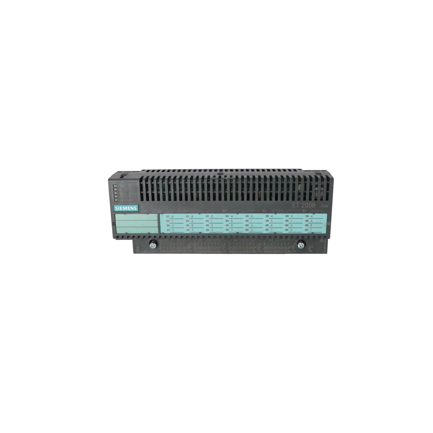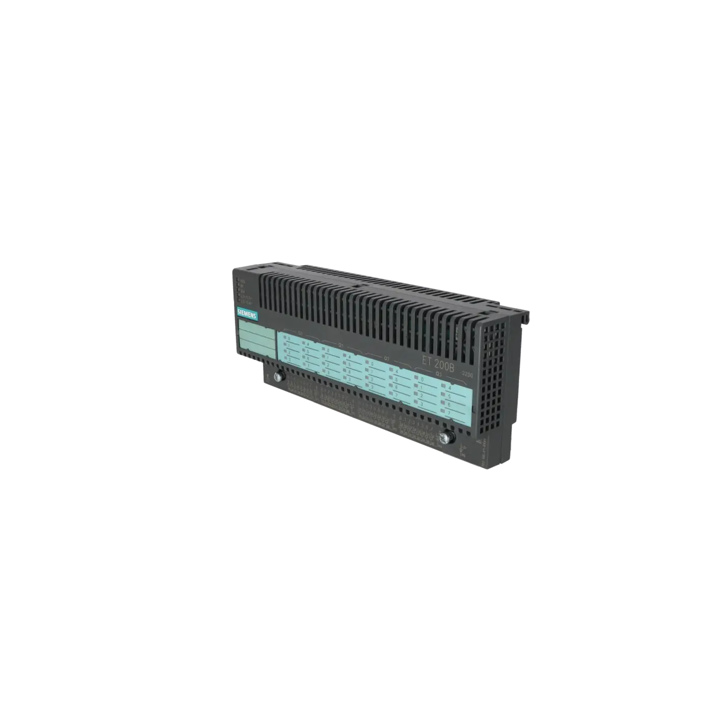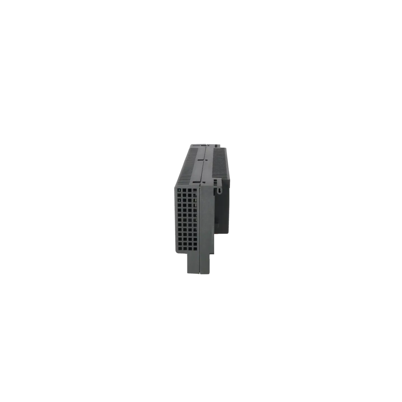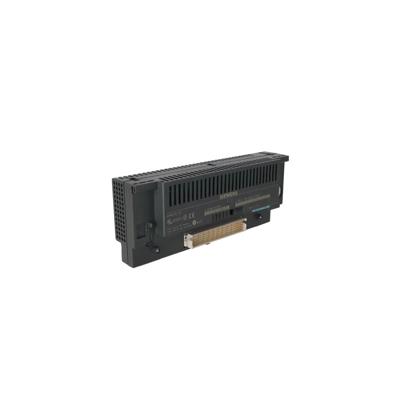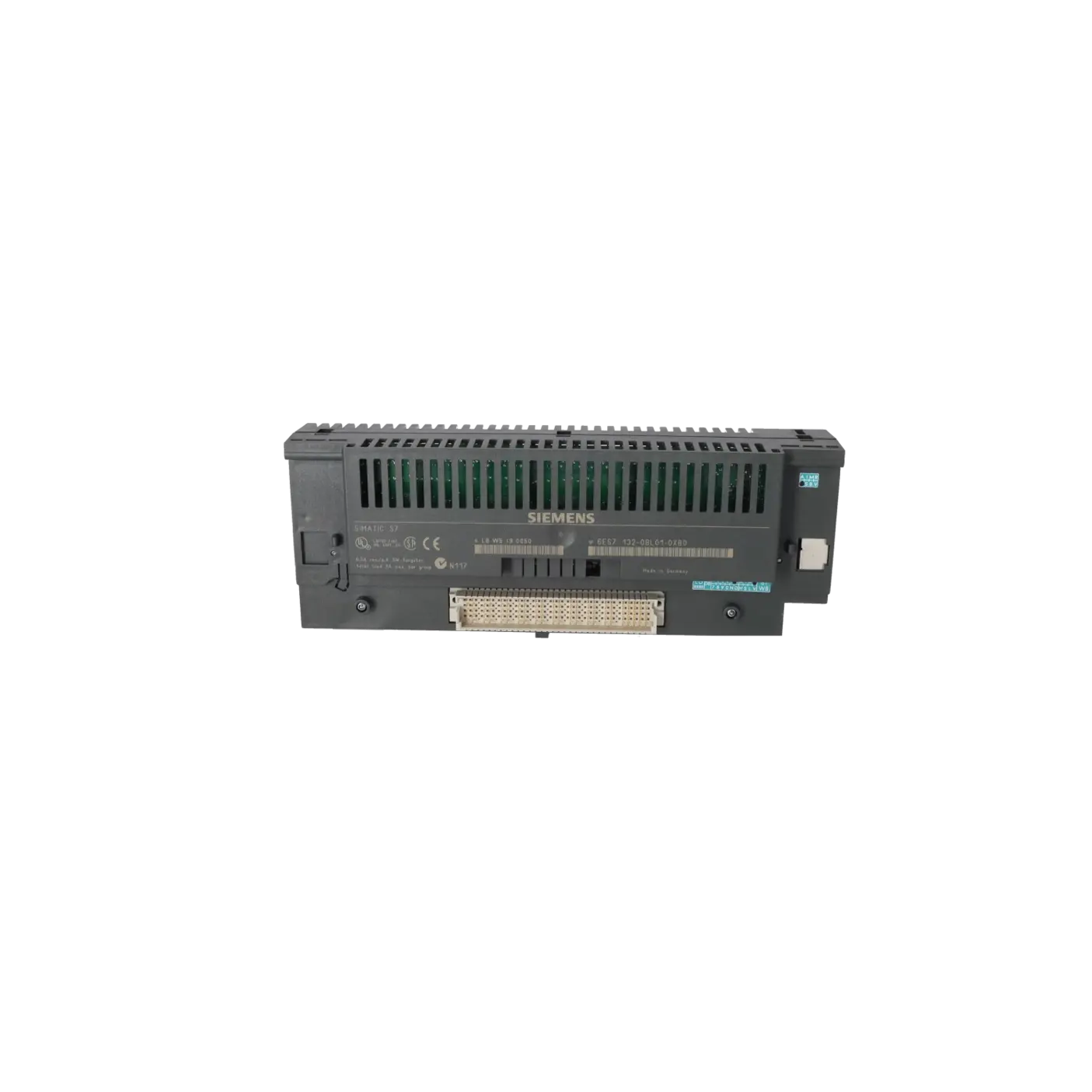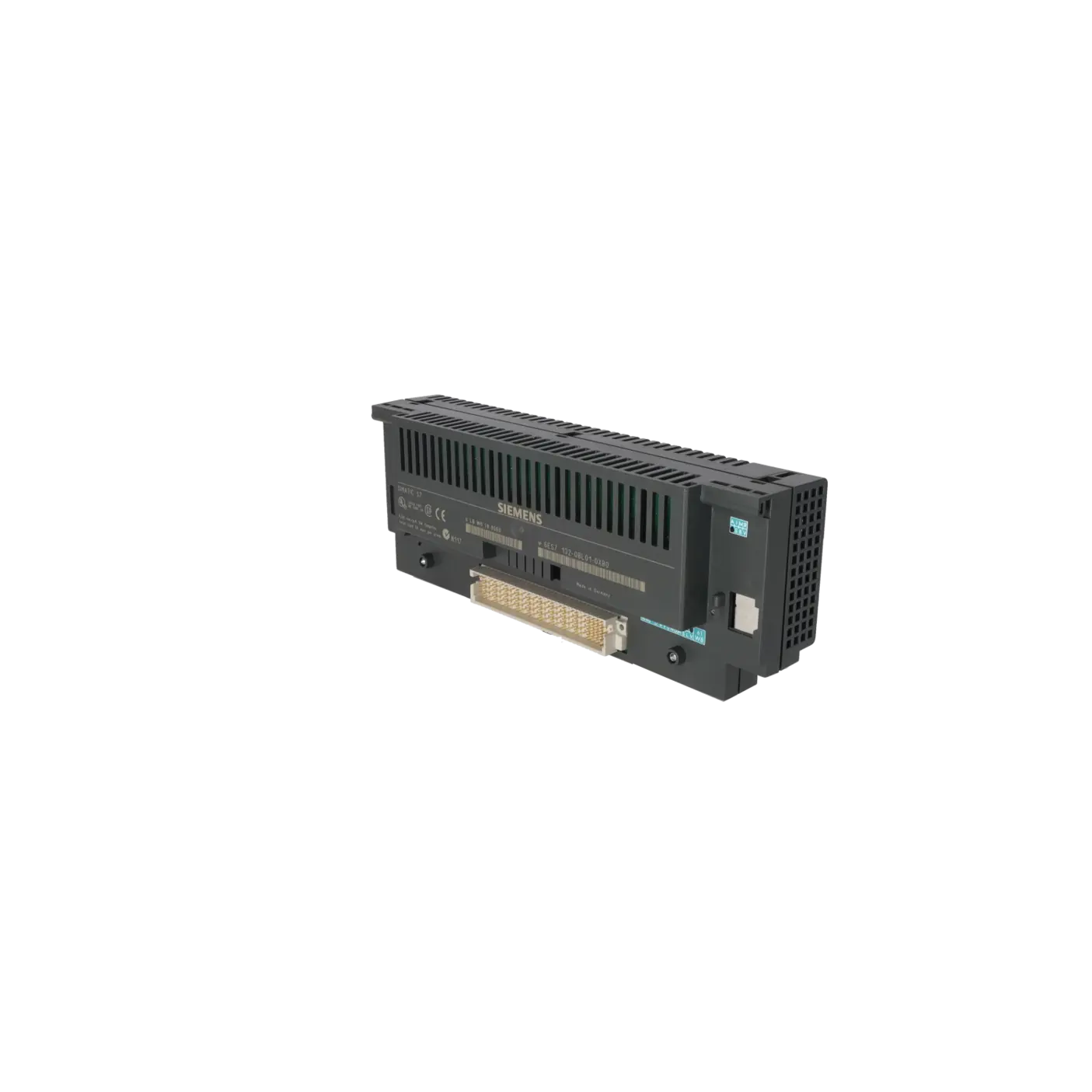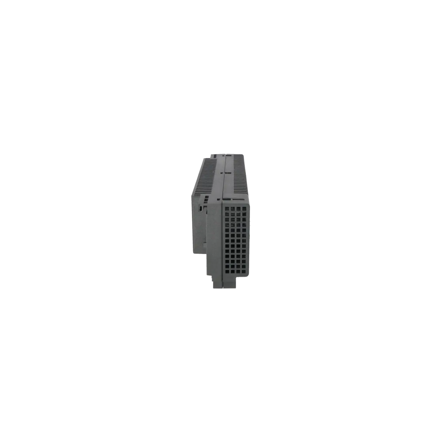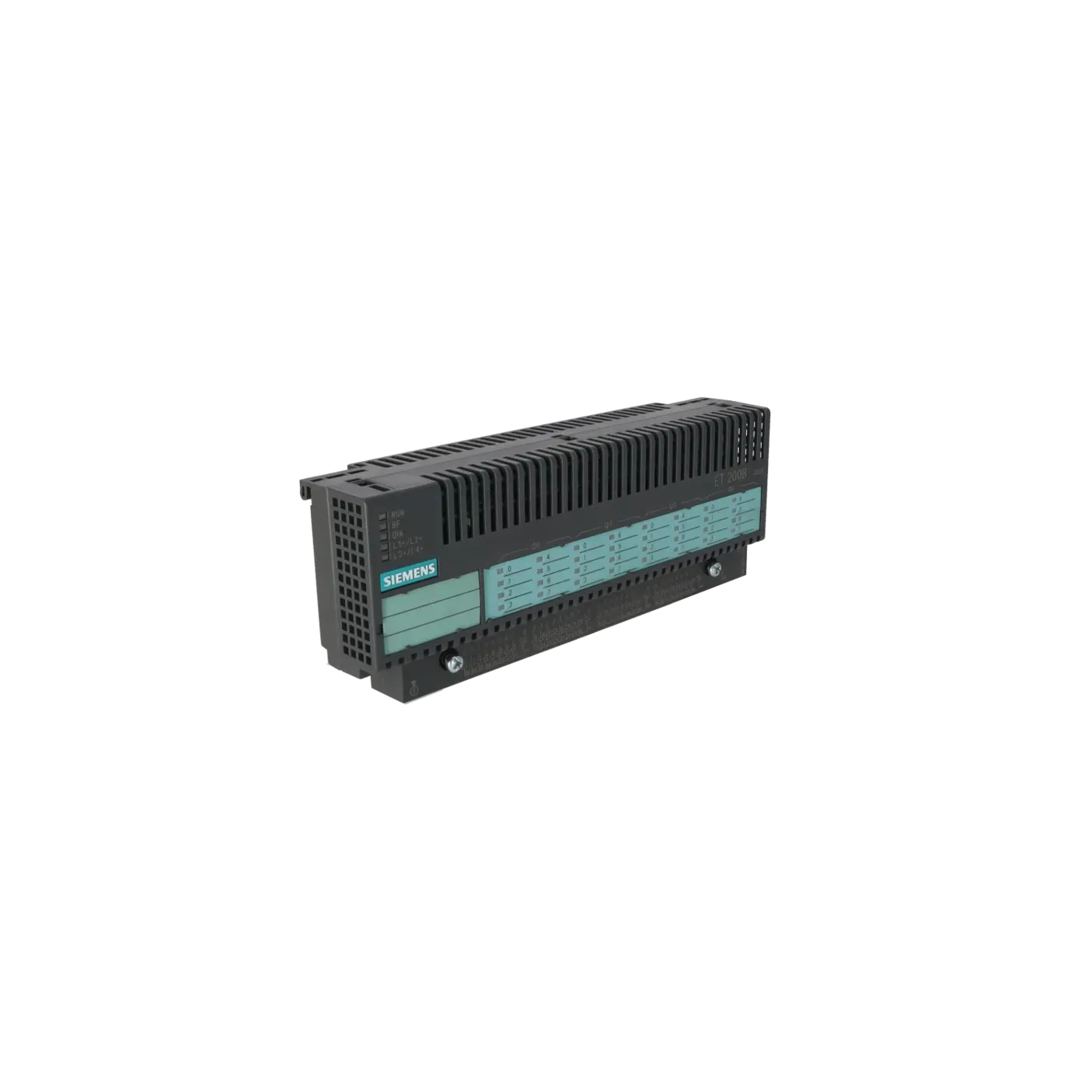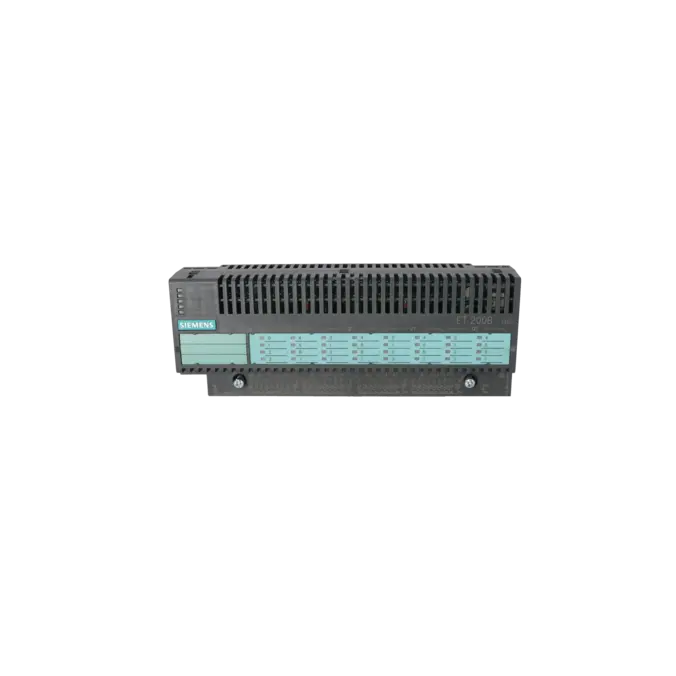
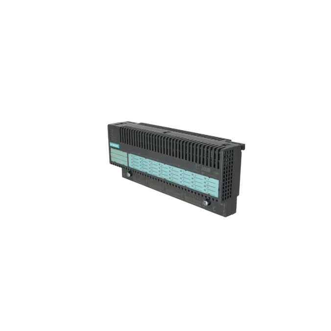
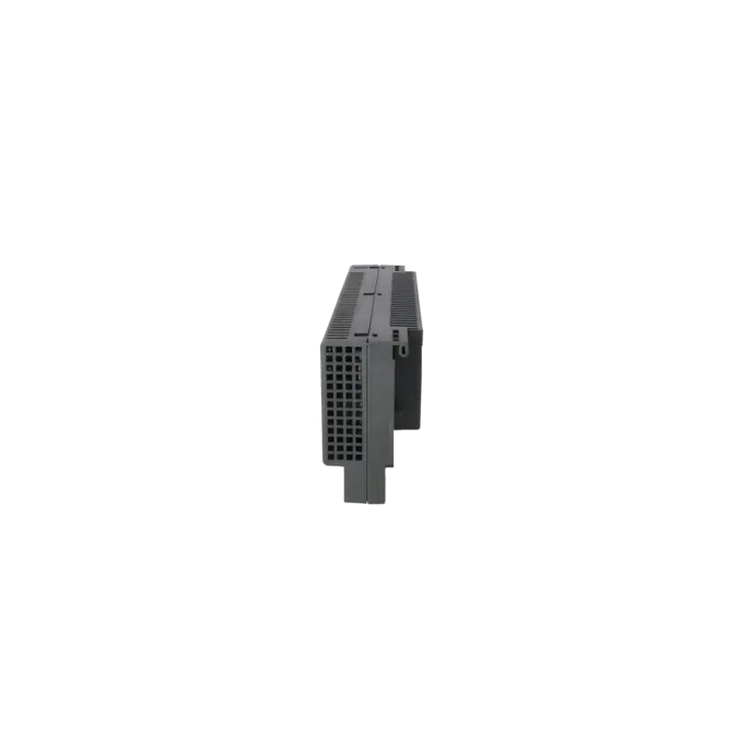
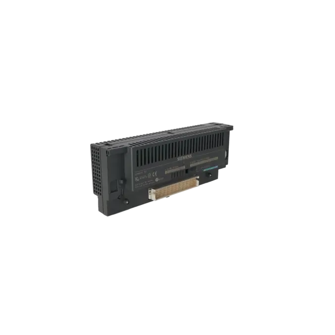
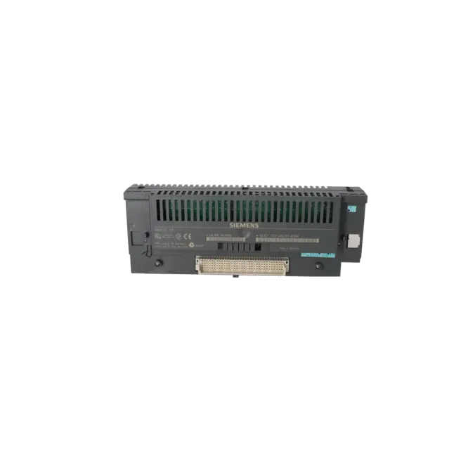
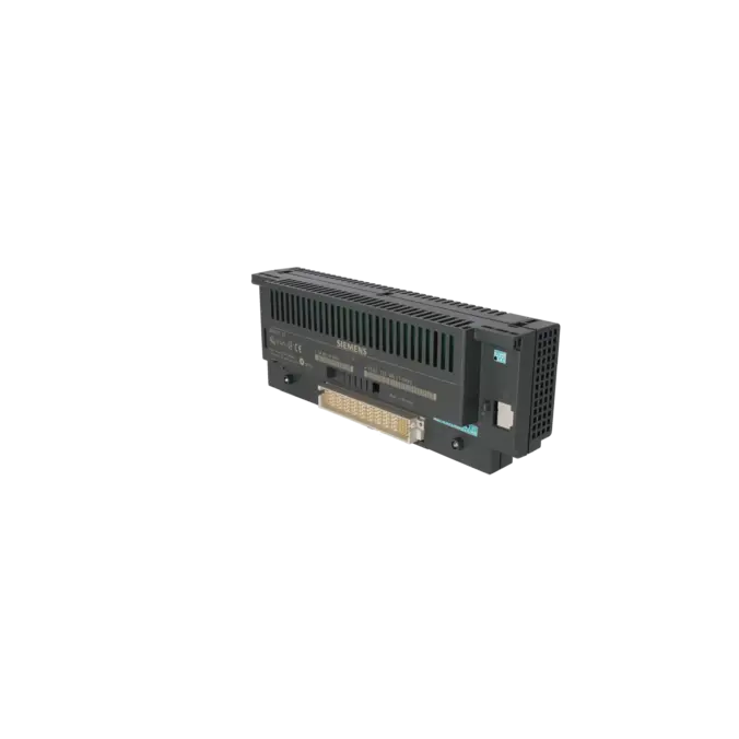
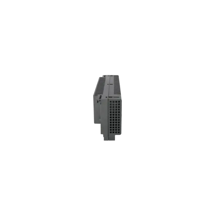
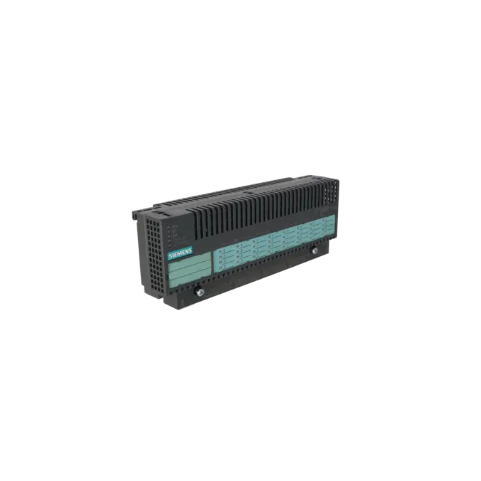
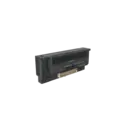
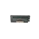
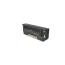
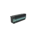
SIEMENS 6ES7132-0BL01-0XB0
- EICHLER-art.no.: K0118074
- EAN: 4025515058120
Product description
SIMATIC DP, ELEKTRONIKMODUL DIGITAL, FUER ET 200B, B=235MM, 32DA, DC 24V, 0,5A
Services for SIEMENS 6ES7132-0BL01-0XB0
Repair
from 681,63 €
to 1.226,93 €
Replacement
Used
New
1.095,00 €
1.040,25 €
SIEMENS |
6ES7132-0BL01-0XB0 –
additional product information
| Delivery information | |||
|---|---|---|---|
| Export identifier | AL: ECCN: | ||
| Net weight | 0.753 | ||
| Quantity | 1 Stück | ||
| Packaging quantity | 1 | ||
| Additional product information | |||
|---|---|---|---|
| Product status | EOP: 2006-10-01 | ||
| EAN | 4025515058120 | ||
| UPC | / | ||
| Static lot number | 85389091 | ||
| List indicator | / | ||
| Product group | 4467 | ||
| Country of origin | DE | ||
| Compliance with the substance restrictions according to RoHS directive | Since: / | ||
| Product classifications | Version | Classification | |
|---|---|---|---|
| eClass | 4 | / | |
| eClass | 5.1 | / | |
| eClass | 6.0 | / | |
| ETIM | 3 | / | |
| ETIM | 4 | / | |
| ETIM | 5 | / | |
What is the 6ES7132-0BL01-0XB0 and where is it used?
The 6ES7132-0BL01-0XB0 is a digital electronics assembly from the Siemens SIMATIC DP / ET 200B product range. It is a 32-channel digital output assembly for 24 V DC applications, with an output current rating of 0.5 A per channel. The assembly is designed for distributed I/O architectures based on PROFIBUS DP and is typically used wherever actuators must be controlled outside the central control cabinet. Typical applications include solenoid valves, DC contactors, signalling devices and other 24 V DC loads in machinery and production systems. For maintenance engineers, the assembly is particularly relevant when an existing ET 200B station must be preserved exactly, replaced quickly or returned to service reliably after a fault.
Overview of the key technical data and what it means
The most important specifications are straightforward from a practical perspective: 32 digital outputs, 24 V DC operation, 0.5 A per channel, galvanic isolation in groups of eight channels, a maximum group current of 2 A and PROFIBUS DP communication at up to 12 Mbit/s. These characteristics mean that the assembly is suitable for many standard switching applications in distributed automation systems, although loads must be carefully planned according to the channel groups. The grouping concept simplifies diagnostics because faults such as missing load voltage or short circuits can be isolated to specific groups. Supported terminal blocks include the TB2/DC, TB2-4/DC, TB4/DC and TB4M/DC variants. The assembly also provides diagnostic and status indicators such as RUN, BF and group-specific load-voltage indications.
Product status, life-cycle status and obsolescence
For operators of older PROFIBUS-based systems, the product status is particularly important. The EICHLER product page lists an EOP (End of Production) date of 1 October 2006 for the 6ES7132-0BL01-0XB0. Siemens also classifies the assembly as discontinued, and the available product information indicates that no replacement product has been assigned. This clearly places the assembly within the category of obsolete equipment. For purchasing and maintenance departments, this means that long-term support can generally no longer rely on standard manufacturer supply channels but instead depends on stockholding strategies, tested spare parts, replacement solutions and repair capabilities. A verified official Siemens one-to-one replacement for this assembly is currently not available.
Available EICHLER services and their practical benefits
For obsolete ET 200B equipment, the services offered by EICHLER are particularly relevant in practice: repair, replacement, used parts and new parts. Repair is especially valuable when a system must return to operation quickly while preserving the existing wiring, addressing and mechanical design. According to the EICHLER product information, the repair service includes technical cleaning, preventive maintenance, comprehensive functional testing and a minimum 24-month warranty. Replacement services and used parts are particularly attractive when the cost of a breakdown is high and a functionally tested replacement assembly is required at short notice. Following product discontinuation, these service options play an important role in maintaining the operational reliability of existing systems and reducing the risks associated with obsolescence in a controlled and predictable manner.
| Attribute | Value |
|---|---|
| Usable terminal block | TB2/DC, TB2-4/DC, TB4/DC, TB4-4/DC |
| Supply voltage | |
| Rated value (DC) | 24 V; L1+, L2+, L3+, L4+, L5+; value at t < 0.5 s: 35 V |
| permissible range, lower limit (DC) | 18.5 V |
| permissible range, upper limit (DC) | 30.2 V |
| Input current | |
| Current consumption, typ. | 75 mA; From L5+; logic |
| I²t | 0.05 A²·s; with starting current inrush |
| Power loss | |
| Power loss, max. | 7.9 W |
| Digital outputs | |
| Number of digital outputs | 32 |
| Short-circuit protection | Yes; Electronic |
| Limitation of inductive shutdown voltage to | typ. (L1+ to L4+) -55 V |
| Controlling a digital input | Yes |
| Switching capacity of the outputs | |
| ● on lamp load, max. | 5 W |
| Output voltage | |
| ● Rated value (DC) | 24 V |
| ● for signal "0", max. | 2 V; idling |
| ● for signal "1", min. | UE -3 V |
| Output current | |
| ● for signal "1" permissible range, max. | 0.5 A; in groups of 8 |
| ● for signal "0" residual current, max. | 1 mA |
| Output delay with resistive load | |
| ● "0" to "1", max. | 20 µs |
| ● "1" to "0", max. | 0.5 ms |
| Switching frequency | |
| ● with resistive load, max. | 100 Hz |
| ● with inductive load, max. | 0.5 Hz |
| ● on lamp load, max. | 8 Hz |
| Total current of the outputs (per group) | |
| all mounting positions | |
| — up to 60 °C, max. | 2 A |
| Cable length | |
| ● unshielded, max. | 100 m |
| Interfaces | |
| PROFIBUS DP | |
| ● Transmission rate, max. | 12 Mbit/s |
| Protocols | |
| Bus protocol/transmission protocol | PROFIBUS DP |
| PROFIBUS DP | |
| Services | |
| — SYNC capability | Yes |
| Interrupts/diagnostics/status information | |
| Diagnostics indication LED | |
| ● RUN LED | Yes |
| ● Bus fault BF (red) | Yes |
| ● Status indicator digital output (green) | Yes |
| Potential separation | |
| between electronic block and PROFIBUS DP | Yes |
| Potential separation digital outputs | |
| ● Potential separation digital outputs | Yes |
| ● between the channels, in groups of | 8 |
| Ambient conditions | |
| Ambient temperature during operation | |
| ● horizontal installation, min. | 0 °C |
| ● horizontal installation, max. | 60 °C; 40°C for other mountings |
| Air pressure acc. to IEC 60068-2-13 | |
| ● permissible range, lower limit | 795 hPa |
| ● permissible range, upper limit | 1 080 hPa |
| Relative humidity | |
| ● Operation, min. | 15 % |
| ● Operation, max. | 95 %; RH class 2 in accordance with IEC 1131-2 |
| Vibrations | |
| ● Operation, tested according to IEC 60068-2-6 | Yes; IEC 68, Part 2-6; 10 to 57 Hz; (constant amplitude 0.075 mm); 57 to 150 Hz; (constant acceleration 1 g) |
| Shock testing | |
| ● tested according to IEC 60068-2-27 | Yes; IEC 68, Part 2-27; half-sine, 15 g, 11 ms |
| Connection method | |
| Design of electrical connection for the inputs and outputs | Screw-type and spring-loaded terminals, permanent wiring; 3 and 4-wire connection |
| Dimensions | |
| Width | 235 mm; EB and TB |
| Height | 130 mm; EB and TB |
| Depth | 60 mm; EB and TB |
| Weights | |
| Weight, approx. | 800 g; EB and TB |
| Fault Description | Possible Solution |
|---|---|
| Why is the BF LED illuminated red on the 6ES7132-0BL01-0XB0? | On an ET 200B station, the BF indicator typically signals that the station is no longer being addressed correctly by the DP master or that it has not yet been parameterised during start-up. First check the PROFIBUS DP master, the station parameterisation and the bus connection. If the fault occurs repeatedly, also inspect the termination resistors and check for address conflicts. If the problem appears after a brief power interruption or following changes to the configuration or transmission rate, set the STOP/RUN switch to STOP and then back to RUN. |
| Why is the DIA LED illuminated red on the 6ES7132-0BL01-0XB0? | On digital 24 V output assemblies, a red DIA LED indicates that at least one output channel has reported a fault, typically a short circuit or missing load voltage. Read the slave diagnostics and use the channel groups 0 to 3 to narrow down the affected area. Then disconnect the connected loads group by group, inspect the relevant actuator, check the wiring to M and measure the load supply voltage for the affected group. |
| Why is the load voltage missing at L1+/L2+ or L3+/L4+ on the 6ES7132-0BL01-0XB0? | The assembly monitors the load voltage for each output group. If the supply to a group fails, the corresponding load-voltage indicator will not be active, and diagnostics may report a missing load voltage or a blown fuse. Check that the 24 V supply is within the permissible range, inspect the associated fuse, verify the wiring of the group supply and check the M1 to M4 reference connections. Afterwards, reconnect the loads step by step to identify any faulty consumer reliably. |
| Why does an output of the 6ES7132-0BL01-0XB0 fail to switch correctly even though the signal is present from the CPU? | In many cases, the cause is not the CPU itself but an overloaded output stage or an unsuitable load. The maximum permissible load is 0.5 A per channel, 5 W for lamp loads and 2 A per output group. Inductive loads must also be operated at relatively low switching frequencies. Therefore, check the load current, inrush current and the type of load connected. For loads operating close to the specified limits, an interposing relay or appropriate suppression circuitry is often the more robust solution. |
| Why is the ET 200B station not re-establishing communication after a power cycle or configuration change? | Siemens documents that, in exceptional cases, an ET 200B station may fail to rejoin the PROFIBUS DP network after repeated short power interruptions. Similarly, correcting an invalid configuration while simultaneously changing the baud rate can prevent the station from starting up correctly. In both situations, first verify the configuration in the DP master and then set the STOP/RUN switch to STOP before returning it to RUN. This procedure often restores normal communication and allows the station to be reintegrated into the PROFIBUS network. |
Is the 6ES7132-0BL01-0XB0 still available through standard supply channels?
From a life-cycle perspective, the assembly has been discontinued. The EICHLER product page lists an EOP (End of Production) date of 1 October 2006, and the Siemens product portal identifies the assembly as a cancelled product. In practical terms, this means that procurement is now typically based on available stock, functionally tested replacement assemblies, exchange services or repair solutions rather than predictable manufacturer-led standard supply.
Is there an official Siemens successor to the 6ES7132-0BL01-0XB0?
At present, no verified official successor has been identified. In the Siemens product portal, the assembly is shown as discontinued without a replacement product. For operators, this means that any future modernisation should be viewed as a migration or system-upgrade project rather than a straightforward one-to-one hardware replacement based on a manufacturer-designated successor.
Which terminal blocks are compatible with the 6ES7132-0BL01-0XB0?
According to Siemens, the assembly can be used with the terminal blocks TB2/DC, TB2-4/DC, TB4/DC and TB4M/DC. This information is particularly important for purchasing and maintenance teams because a replacement assembly can only be installed without modification if the electronics module, wiring concept and terminal block are all compatible with one another.
What types of loads is the 6ES7132-0BL01-0XB0 designed to switch?
Siemens specifies that the assembly is suitable for controlling solenoid valves and DC contactors. This makes it well suited to typical 24 V DC actuator applications found in packaging systems, conveyor installations, assembly machinery and process plants. It is important to remain within the specified operating limits to ensure long-term stability of the output stages and to avoid triggering group-related diagnostic messages.
How much current can be drawn per output and per group?
The maximum permissible load is 0.5 A per output channel. In addition, a maximum total current of 2 A per output group applies at ambient temperatures up to 60 °C. In practice, this is a critical consideration because, with 32 outputs available, it is not sufficient to consider only the load on an individual channel. The total load across each group of eight outputs must also be taken into account. Proper load distribution helps prevent failures and simplifies troubleshooting.
How can I quickly determine whether the fault is related to the bus or the load supply?
The front-panel indicators provide a useful first-level diagnostic tool on site. The RUN indicator shows the operating status of the station, BF points to bus or parameterisation issues, DIA on digital DC output assemblies typically indicates a short circuit or missing load voltage, and the L1+/L2+ and L3+/L4+ indicators display the status of the group-related output supply voltages. These indicators often allow maintenance personnel to determine quickly whether the problem is related to communication, configuration or the load circuit, even before carrying out more detailed diagnostic analysis.