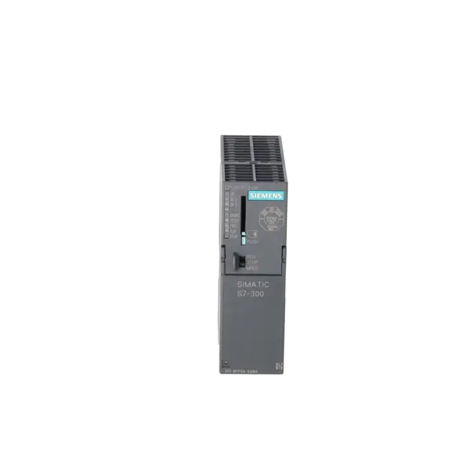
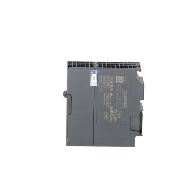
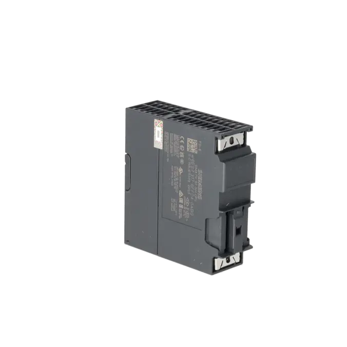
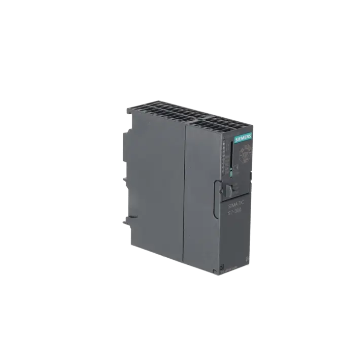
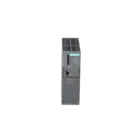
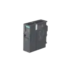
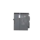
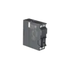
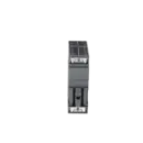
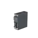
SIEMENS 6ES7317-6FF04-0AB0
-
SIEMENS | PLC Controls | Central Processing Units
- EICHLER-art.no.: K0252215
- EAN: 4025515080190
- UPC: 040892788624
Product description
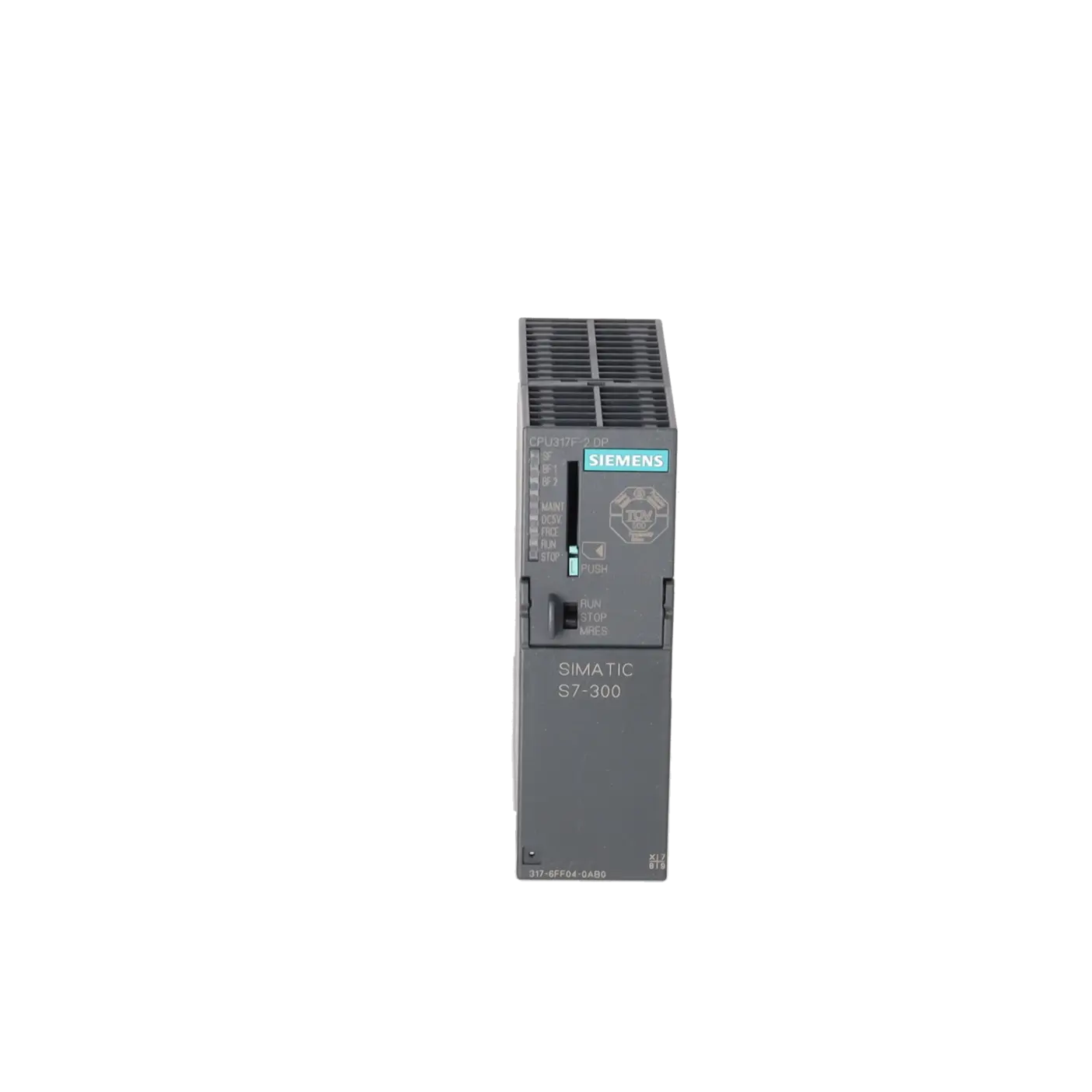
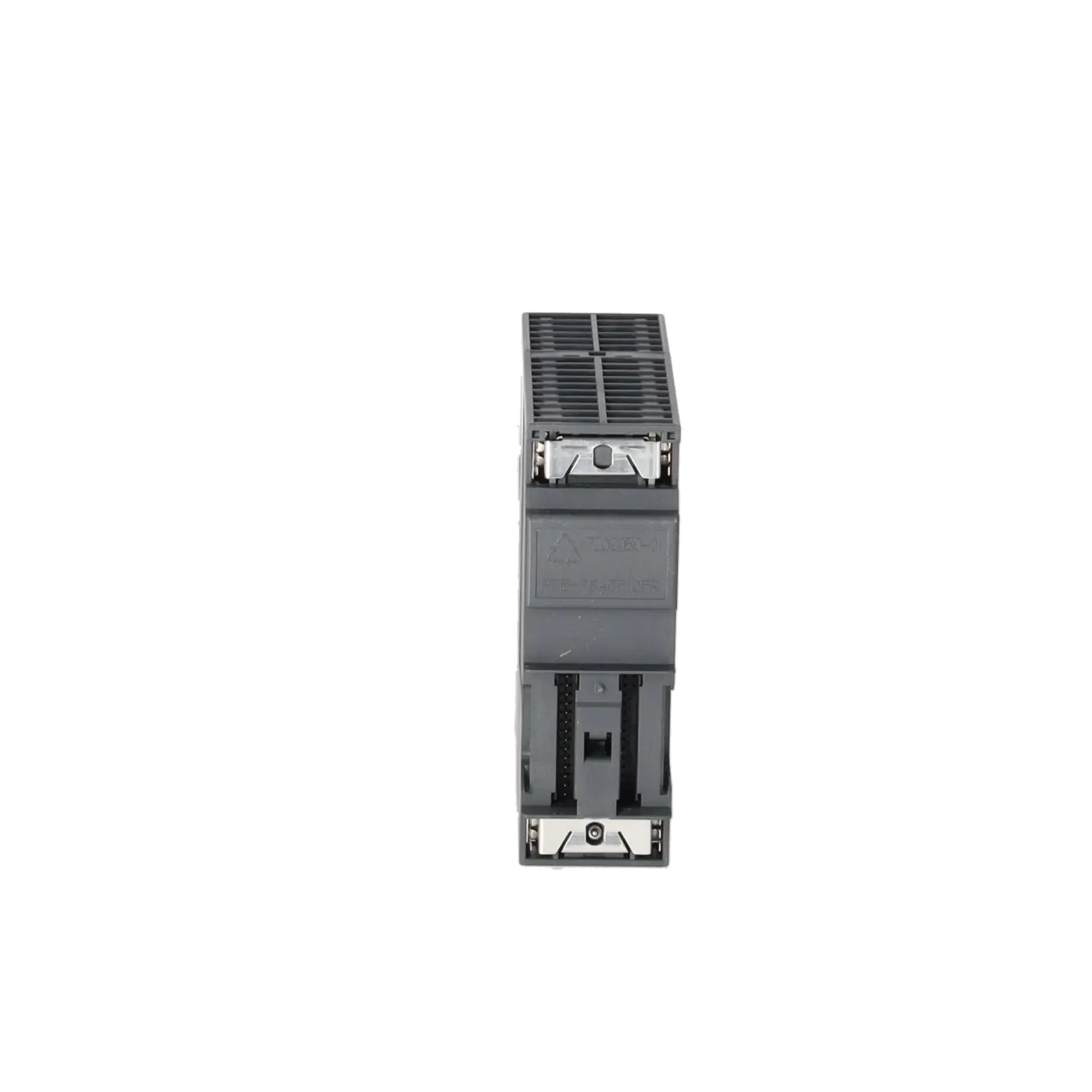
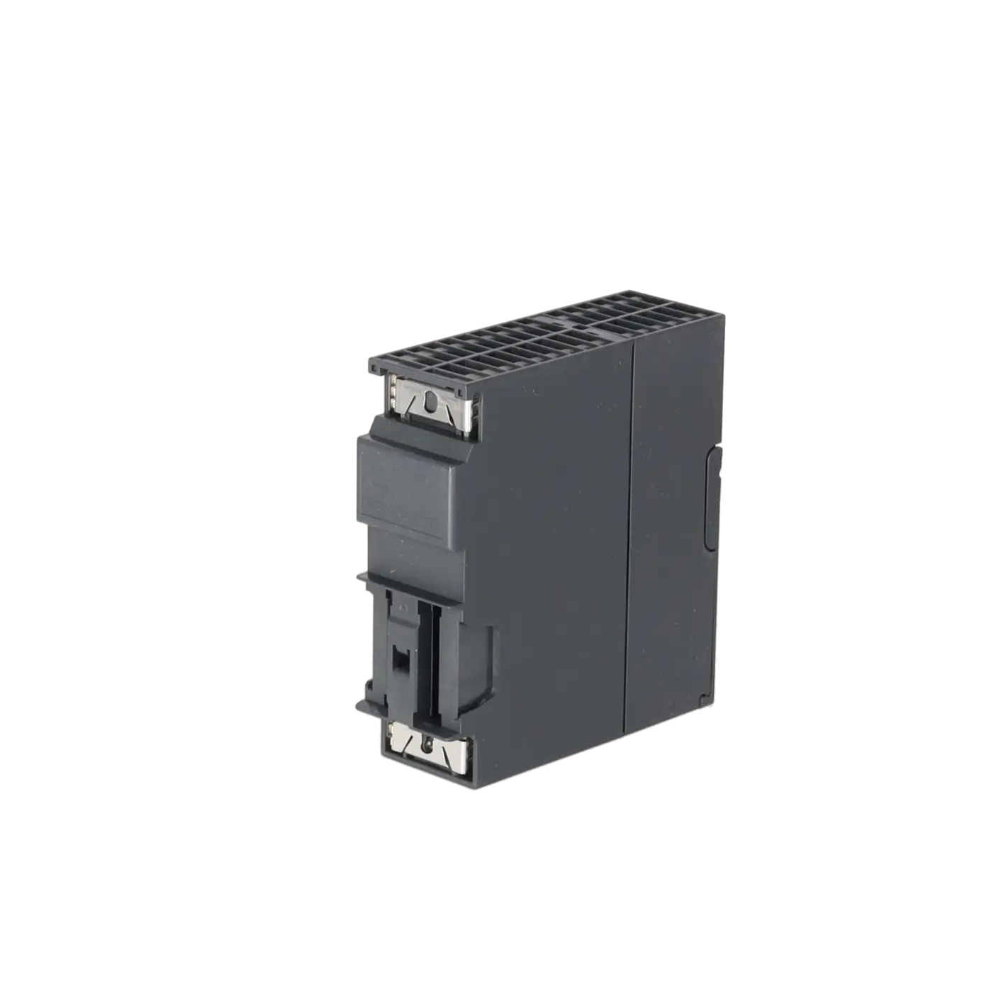
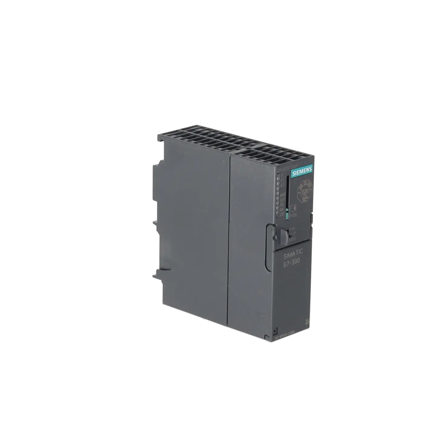
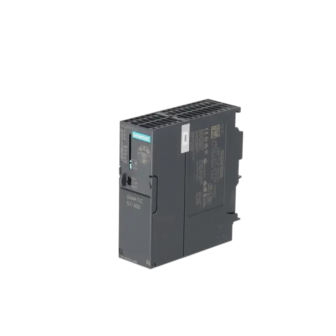
SIMATIC S7-300, CPU 317F-2DP, CENTRAL PROCESSING UNIT WITH 1.5 MB WORK MEMORY, 1ST INTERFACE MPI/DP 12 MBIT/S, 2ND INTERFACE DP MASTER/SLAVE MICRO MEMORY CARD REQUIRED CAN BE USED WITH SOFTWARE PACKAGE S7 DISTRIBUTED SAFETY V5.2 SP1 OR HIGHER
Services for SIEMENS 6ES7317-6FF04-0AB0
Repair
from 1.879,02 €
to 3.035,34 €
Replacement
Used
5.572,21 €
4.179,16 €
New
7.227,00 €
5.420,25 €
SIEMENS |
6ES7317-6FF04-0AB0 –
additional product information
| Delivery information | |||
|---|---|---|---|
| Export identifier | AL: N ECCN: EAR99H | ||
| Net weight | 0.416 | ||
| Quantity | 1 Stück | ||
| Packaging quantity | 1 | ||
| Additional product information | |||
|---|---|---|---|
| Product status | |||
| EAN | 4025515080190 | ||
| UPC | 040892788624 | ||
| Static lot number | 85371091 | ||
| List indicator | ST73 | ||
| Product group | 4A89 | ||
| Country of origin | DE | ||
| Compliance with the substance restrictions according to RoHS directive | Since: 20110318 | ||
| Product classifications | Version | Classification | |
|---|---|---|---|
| eClass | 4 | / | |
| eClass | 5.1 | 27-24-22-07 | |
| eClass | 6.0 | 27-24-22-07 | |
| ETIM | 3 | / | |
| ETIM | 4 | EC000236 | |
| ETIM | 5 | EC000236 | |
What is 6ES7317-6FF04-0AB0 and where is it used?
6ES7317-6FF04-0AB0 is a SIMATIC S7-300 CPU 317F-2 DP from Siemens, a fail-safe central processing assembly designed for automation applications with safety requirements. The CPU is typically used in legacy systems where traditional STEP 7/S7-300 architectures, PROFIBUS DP networks, and safety-related functions such as emergency stop circuits, safety gate monitoring, or safe shutdown functions are implemented. For maintenance personnel, the assembly is particularly relevant when an existing S7-300F system must continue operating reliably, a failed CPU has to be replaced quickly, or a safe restart after downtime needs to be organised. For purchasing and production departments, it is especially important because it remains the central control element in many older yet still production-critical machines.
Overview of the key technical data and what they mean
The CPU operates on 24 V DC within a permissible voltage range of 19.2 to 28.8 V DC and requires a SIMATIC Micro Memory Card (MMC) for program and load memory storage. The 1.5 MB work memory is designed for more complex standard and safety applications within existing S7-300 environments. In terms of communication, the CPU provides two integrated RS-485 interfaces: one configured as MPI/DP and the other as a DP master/DP slave interface. PROFINET is not integrated in this model. The CPU supports PROFIBUS data rates up to 12 Mbit/s and up to 124 DP devices per DP master interface. Operation requires STEP 7 V5.5 + SP1 or STEP 7 V5.2 + SP1 with HSP 202, together with Distributed Safety. In practical terms, this means excellent integration into traditional PROFIBUS-based safety systems, but without the features of a modern PROFINET-enabled CPU.
Product status, life cycle status and obsolescence
Siemens currently lists the 6ES7317-6FF04-0AB0 as a spare part. At the same time, Siemens has already announced the product phase-out for the SIMATIC S7-300 / ET 200M product families: PM400 became effective on 01 October 2023, while PM410 is scheduled for 01 October 2025. After that date, according to Siemens, components will only remain available as spare parts, with spare parts support for the product family planned until approximately 01 October 2033. No direct plug-compatible successor still in active production has been identified in the Siemens sources reviewed. For migration projects, Siemens specifies the CPU 1516F-3 PN/DP in its S7-300 to S7-1500 migration guide. However, this represents a planned platform migration, not a simple hardware replacement.
Available EICHLER services and when they are relevant
For business customers, EICHLER offers several practical options for this CPU. Repair is particularly attractive when the existing assembly is intended to return to the installed safety and control environment, and a rapid, cost-effective return to service is the priority. According to the product page, the repair service includes technical cleaning, preventive maintenance, comprehensive functional testing, and a minimum 24-month warranty. Exchange is appropriate when downtime is critical and a fast replacement solution is required. Used units help reduce procurement risks in obsolete S7-300 environments, while new units are relevant when maximum availability and a clearly defined hardware condition are required. In addition, an optional F-CPU test report is available, which is particularly valuable for safety-related applications, supporting maintenance, quality assurance, and documentation requirements.
| Attribute | Value |
|---|---|
| General information | |
| Product type designation | CPU 317F-2 DP |
| HW functional status | 1 |
| Firmware version | V3.3 |
| Engineering with | |
| ● Programming package | STEP 7 V5.5 + SP1 or higher or STEP 7 V5.2 + SP1 or higher with HSP 202 + Distributed Safety |
| Supply voltage | |
| Rated value (DC) | 24 V |
| permissible range, lower limit (DC) | 19.2 V |
| permissible range, upper limit (DC) | 28.8 V |
| external protection for power supply lines (recommendation) | 2 A min. |
| Input current | |
| Current consumption (rated value) | 870 mA |
| Current consumption (in no-load operation), typ. | 120 mA |
| Inrush current, typ. | 4 A |
| I²t | 1 A²·s |
| Power loss | |
| Power loss, typ. | 4.5 W |
| Memory | |
| Work memory | |
| ● integrated | 1 536 kbyte |
| ● expandable | No |
| Load memory | |
| ● Plug-in (MMC) | Yes |
| ● Plug-in (MMC), max. | 8 Mbyte |
| ● Data management on MMC (after last programming), min. | 10 a |
| Backup | |
| ● present | Yes; Guaranteed by MMC (maintenance-free) |
| ● without battery | Yes; Program and data |
| CPU processing times | |
| for bit operations, typ. | 0.025 µs |
| for word operations, typ. | 0.03 µs |
| for fixed point arithmetic, typ. | 0.04 µs |
| for floating point arithmetic, typ. | 0.16 µs |
| CPU-blocks | |
| Number of blocks (total) | 2 048; (DBs, FCs, FBs); the maximum number of loadable blocks can be reduced by the MMC used. |
| DB | |
| ● Number, max. | 2 048; Number range: 1 to 16000 |
| ● Size, max. | 64 kbyte |
| FB | |
| ● Number, max. | 2 048; Number range: 0 to 7999 |
| ● Size, max. | 64 kbyte |
| FC | |
| ● Number, max. | 2 048; Number range: 0 to 7999 |
| ● Size, max. | 64 kbyte |
| OB | |
| ● Number, max. | see instruction list |
| ● Size, max. | 64 kbyte |
| ● Number of free cycle OBs | 1; OB 1 |
| ● Number of time alarm OBs | 1; OB 10 |
| ● Number of delay alarm OBs | 2; OB 20, 21 |
| ● Number of cyclic interrupt OBs | 4; OB 32, 33, 34, 35 |
| ● Number of process alarm OBs | 1; OB 40 |
| ● Number of DPV1 alarm OBs | 3; OB 55, 56, 57 |
| ● Number of isochronous mode OBs | 1; OB 61 |
| ● Number of startup OBs | 1; OB 100 |
| ● Number of asynchronous error OBs | 5; OB 80, 82, 85, 86, 87 |
| ● Number of synchronous error OBs | 2; OB 121, 122 |
| Nesting depth | |
| ● per priority class | 16 |
| ● additional within an error OB | 4 |
| Counters, timers and their retentivity | |
| S7 counter | |
| ● Number | 512 |
| Retentivity | |
| — adjustable | Yes |
| — preset | Z 0 to Z 7 |
| Counting range | |
| — lower limit | 0 |
| — upper limit | 999 |
| IEC counter | |
| ● present | Yes |
| ● Type | SFB |
| ● Number | Unlimited (limited only by RAM capacity) |
| S7 times | |
| ● Number | 512 |
| Retentivity | |
| — adjustable | Yes |
| — preset | No retentivity |
| Time range | |
| — lower limit | 10 ms |
| — upper limit | 9 990 s |
| IEC timer | |
| ● present | Yes |
| ● Type | SFB |
| ● Number | Unlimited (limited only by RAM capacity) |
| Data areas and their retentivity | |
| Retentive data area (incl. timers, counters, flags), max. | 256 kbyte |
| Flag | |
| ● Size, max. | 4 096 byte |
| ● Retentivity available | Yes; From MB 0 to MB 4 095 |
| ● Retentivity preset | MB 0 to MB 15 |
| ● Number of clock memories | 8; 1 memory byte |
| Data blocks | |
| ● Retentivity adjustable | Yes; via non-retain property on DB |
| ● Retentivity preset | Yes |
| Local data | |
| ● per priority class, max. | 32 768 byte; Max. 2048 bytes per block |
| Address area | |
| I/O address area | |
| ● Inputs | 8 192 byte |
| ● Outputs | 8 192 byte |
| of which distributed | |
| — Inputs | 8 192 byte |
| — Outputs | 8 192 byte |
| Process image | |
| ● Inputs | 8 192 byte |
| ● Outputs | 8 192 byte |
| ● Inputs, adjustable | 8 192 byte |
| ● Outputs, adjustable | 8 192 byte |
| ● Inputs, default | 1 024 byte |
| ● Outputs, default | 1 024 byte |
| Subprocess images | |
| ● Number of subprocess images, max. | 1 |
| Digital channels | |
| ● Inputs | 65 536 |
| — of which central | 1 024 |
| ● Outputs | 65 536 |
| — of which central | 1 024 |
| Analog channels | |
| ● Inputs | 4 096 |
| — of which central | 256 |
| ● Outputs | 4 096 |
| — of which central | 256 |
| Hardware configuration | |
| Number of expansion units, max. | 3 |
| Number of DP masters | |
| ● integrated | 2 |
| ● via CP | 4 |
| Number of operable FMs and CPs (recommended) | |
| ● FM | 8 |
| ● CP, PtP | 8 |
| ● CP, LAN | 10 |
| Rack | |
| ● Racks, max. | 4 |
| ● Modules per rack, max. | 8 |
| Time of day | |
| Clock | |
| ● Hardware clock (real-time) | Yes |
| ● retentive and synchronizable | Yes |
| ● Backup time | 6 wk; At 40 °C ambient temperature |
| ● Deviation per day, max. | 10 s; Typ.: 2 s |
| ● Behavior of the clock following POWER-ON | Clock continues running after POWER OFF |
| ● Behavior of the clock following expiry of backup period | the clock continues at the time of day it had when power was switched off |
| Operating hours counter | |
| ● Number | 4 |
| ● Number/Number range | 0 to 3 |
| ● Range of values | 0 to 2^31 hours (when using SFC 101) |
| ● Granularity | 1 h |
| ● retentive | Yes; Must be restarted at each restart |
| Clock synchronization | |
| ● supported | Yes |
| ● to MPI, master | Yes |
| ● on MPI, device | Yes |
| ● to DP, master | Yes; With DP slave only slave clock |
| ● on DP, device | Yes |
| ● in AS, master | Yes |
| ● in AS, device | Yes |
| ● on Ethernet via NTP | No |
| Digital inputs | |
| Number of digital inputs | 0 |
| Digital outputs | |
| Number of digital outputs | 0 |
| Analog inputs | |
| Number of analog inputs | 0 |
| Interfaces | |
| Number of PROFINET interfaces | 0 |
| Number of RS 485 interfaces | 2 |
| Number of RS 422 interfaces | 0 |
| 1. Interface | |
| Interface type | Integrated RS 485 interface |
| Isolated | Yes |
| Interface types | |
| ● RS 485 | Yes |
| ● Output current of the interface, max. | 200 mA |
| Protocols | |
| ● MPI | Yes |
| ● PROFIBUS DP master | Yes |
| ● PROFIBUS DP device | Yes; A DP slave at both interfaces simultaneously is not possible |
| ● Point-to-point connection | No |
| MPI | |
| ● Transmission rate, max. | 12 Mbit/s |
| Services | |
| — PG/OP communication | Yes |
| — Routing | Yes |
| — Global data communication | Yes |
| — S7 basic communication | Yes |
| — S7 communication | Yes; Only server, configured on one side |
| — S7 communication, as client | No; but via CP and loadable FB |
| — S7 communication, as server | Yes |
| PROFIBUS DP master | |
| ● Transmission rate, max. | 12 Mbit/s |
| ● max. number of DP devices | 124 |
| Services | |
| — PG/OP communication | Yes |
| — Routing | Yes |
| — Global data communication | No |
| — S7 basic communication | Yes; I blocks only |
| — S7 communication | Yes; Only server, configured on one side |
| — S7 communication, as client | No |
| — S7 communication, as server | Yes |
| — Equidistance | Yes |
| — Isochronous mode | No |
| — SYNC/FREEZE | Yes |
| — activation/deactivation of DP devices | Yes |
| — max. number of DP devices that can be activated/deactivated at the same time | 8 |
| — Direct data exchange (slave-to-slave communication) | Yes; as subscriber |
| — DPV1 | Yes |
| Address area | |
| — Inputs, max. | 8 kbyte |
| — Outputs, max. | 8 kbyte |
| User data per DP device | |
| — Inputs, max. | 244 byte |
| — Outputs, max. | 244 byte |
| PROFIBUS DP device | |
| ● Transmission rate, max. | 12 Mbit/s |
| ● automatic baud rate search | Yes; only with passive interface |
| ● Address area, max. | 32 |
| ● User data per address area, max. | 32 byte |
| Services | |
| — PG/OP communication | Yes |
| — Routing | Yes; Only with active interface |
| — Global data communication | No |
| — S7 basic communication | No |
| — S7 communication | Yes; Only server, configured on one side |
| — S7 communication, as client | No |
| — S7 communication, as server | Yes; Connection configured on one side only |
| — Direct data exchange (slave-to-slave communication) | Yes |
| — DPV1 | No |
| Transfer memory | |
| — Inputs | 244 byte |
| — Outputs | 244 byte |
| 2. Interface | |
| Interface type | Integrated RS 485 interface |
| Isolated | Yes |
| Interface types | |
| ● RS 485 | Yes |
| ● Output current of the interface, max. | 200 mA |
| Protocols | |
| ● MPI | No |
| ● PROFIBUS DP master | Yes |
| ● PROFIBUS DP device | Yes; A DP slave at both interfaces simultaneously is not possible |
| ● Point-to-point connection | No |
| PROFIBUS DP master | |
| ● Transmission rate, max. | 12 Mbit/s |
| ● max. number of DP devices | 124 |
| Services | |
| — PG/OP communication | Yes |
| — Routing | Yes |
| — Global data communication | No |
| — S7 basic communication | Yes; I blocks only |
| — S7 communication | Yes; Only server, configured on one side |
| — S7 communication, as client | No; but via CP and loadable FB |
| — S7 communication, as server | Yes |
| — Equidistance | Yes |
| — Isochronous mode | Yes; OB 61 |
| — SYNC/FREEZE | Yes |
| — activation/deactivation of DP devices | Yes |
| — max. number of DP devices that can be activated/deactivated at the same time | 8 |
| — Direct data exchange (slave-to-slave communication) | Yes; as subscriber |
| — DPV1 | Yes |
| Address area | |
| — Inputs, max. | 8 192 byte |
| — Outputs, max. | 8 192 byte |
| User data per DP device | |
| — Inputs, max. | 244 byte |
| — Outputs, max. | 244 byte |
| PROFIBUS DP device | |
| ● GSD file | The latest GSD file is available on the Internet (http://www.siemens.com/profibus-gsd) |
| ● Transmission rate, max. | 12 Mbit/s |
| ● automatic baud rate search | Yes; only with passive interface |
| ● Address area, max. | 32 |
| ● User data per address area, max. | 32 byte |
| Services | |
| — PG/OP communication | Yes |
| — Routing | Yes; Only with active interface |
| — Global data communication | No |
| — S7 basic communication | No |
| — S7 communication | Yes; Only server, configured on one side |
| — S7 communication, as client | No; but via CP and loadable FB |
| — S7 communication, as server | Yes |
| — Direct data exchange (slave-to-slave communication) | Yes |
| — DPV1 | No |
| Transfer memory | |
| — Inputs | 244 byte |
| — Outputs | 244 byte |
| Protocols | |
| PROFIsafe | No |
| Communication functions | |
| PG/OP communication | Yes |
| Data record routing | Yes |
| Global data communication | |
| ● supported | Yes |
| ● Number of GD loops, max. | 8 |
| ● Number of GD packets, max. | 8 |
| ● Number of GD packets, transmitter, max. | 8 |
| ● Number of GD packets, receiver, max. | 8 |
| ● Size of GD packets, max. | 22 byte |
| ● Size of GD packet (of which consistent), max. | 22 byte |
| S7 basic communication | |
| ● supported | Yes |
| ● User data per job, max. | 76 byte |
| ● User data per job (of which consistent), max. | 76 byte; 76 bytes (with X_SEND or X_RCV); 64 bytes (with X_PUT or X_GET as server) |
| S7 communication | |
| ● supported | Yes |
| ● as server | Yes |
| ● as client | Yes; Via CP and loadable FB |
| ● User data per job, max. | See online help of STEP 7 (shared parameters of the SFBs/FBs and of the SFCs/FCs of S7 Communication) |
| S5 compatible communication | |
| ● supported | Yes; via CP and loadable FC |
| Number of connections | |
| ● overall | 32 |
| ● usable for PG communication | 31 |
| — reserved for PG communication | 1 |
| — adjustable for PG communication, min. | 1 |
| — adjustable for PG communication, max. | 31 |
| ● usable for OP communication | 31 |
| — reserved for OP communication | 1 |
| — adjustable for OP communication, min. | 1 |
| — adjustable for OP communication, max. | 31 |
| ● usable for S7 basic communication | 30 |
| — reserved for S7 basic communication | 0 |
| — adjustable for S7 basic communication, min. | 0 |
| — adjustable for S7 basic communication, max. | 30 |
| ● usable for routing | X1 as a MPI, max. 10; X1 as DP Master max. 24; X1 as DP Slave (active) max. 14; X2 as DP Master max. 24; X2 as DP Slave (active) max. 14 |
| S7 message functions | |
| Number of login stations for message functions, max. | 32; Depending on the configured connections for PG/OP and S7 basic communication |
| Process diagnostic messages | Yes |
| simultaneously active Alarm_S blocks, max. | 300 |
| Test commissioning functions | |
| Status block | Yes; Up to 2 simultaneously |
| Single step | Yes |
| Number of breakpoints | 4 |
| Status/control | |
| ● Status/control variable | Yes |
| ● Variables | Inputs, outputs, memory bits, DB, times, counters |
| ● Number of variables, max. | 30 |
| — of which status variables, max. | 30 |
| — of which control variables, max. | 14 |
| Forcing | |
| ● Forcing | Yes |
| ● Forcing, variables | Inputs, outputs |
| ● Number of variables, max. | 10 |
| Diagnostic buffer | |
| ● present | Yes |
| ● Number of entries, max. | 500 |
| — adjustable | No |
| — of which powerfail-proof | 100; Only the last 100 entries are retained |
| ● Number of entries readable in RUN, max. | 499 |
| — adjustable | Yes; From 10 to 499 |
| — preset | 10 |
| Service data | |
| ● can be read out | Yes |
| Ambient conditions | |
| Ambient temperature during operation | |
| ● min. | 0 °C |
| ● max. | 60 °C |
| Configuration | |
| Configuration software | |
| ● STEP 7 | Yes; STEP 7 V5.5 + SP1 or higher or STEP 7 V5.3 + SP2 or higher with HSP 203 |
| ● STEP 7 Lite | No |
| Programming | |
| ● Command set | see instruction list |
| ● Nesting levels | 8 |
| ● System functions (SFC) | see instruction list |
| ● System function blocks (SFB) | see instruction list |
| Programming language | |
| — LAD | Yes |
| — FBD | Yes |
| — STL | Yes |
| — SCL | Yes |
| — CFC | Yes |
| — GRAPH | Yes |
| — HiGraph® | Yes |
| Know-how protection | |
| ● User program protection/password protection | Yes |
| ● Block encryption | Yes; With S7 block Privacy |
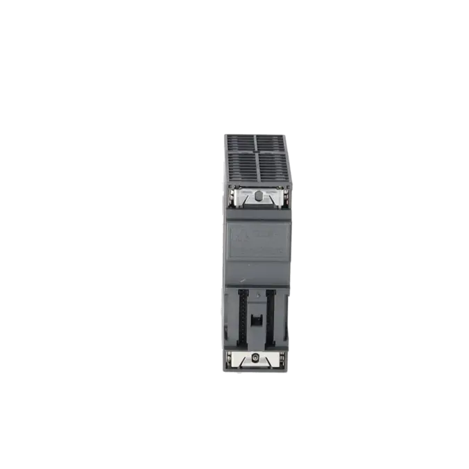
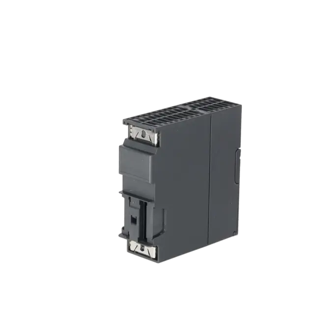
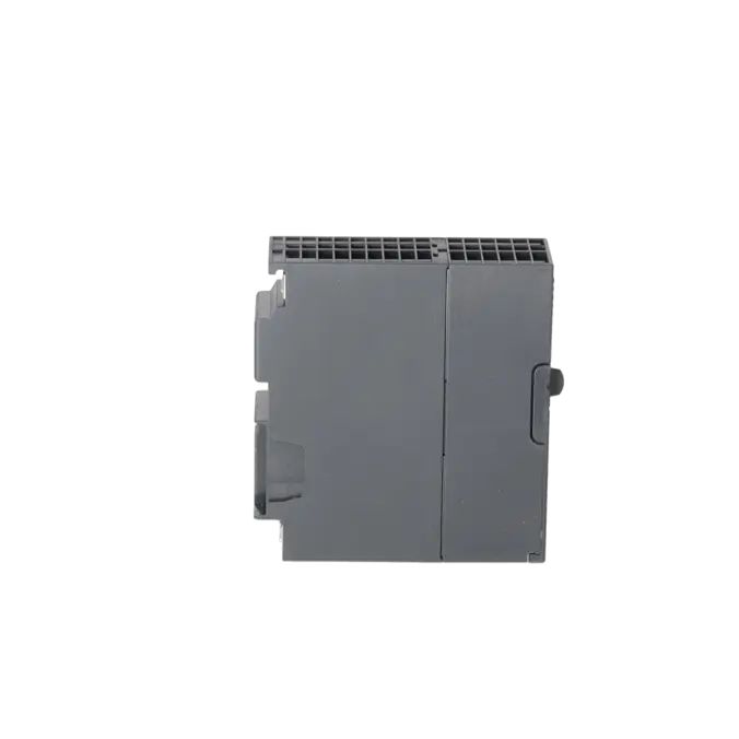
| Dimensions | |
| Width | 40 mm |
| Height | 125 mm |
| Depth | 130 mm |
| Weights | |
| Weight, approx. | 360 g |
| Fault description | Possible solution |
|---|---|
| Why is the red SF LED illuminated on the 6ES7317-6FF04-0AB0 after a CPU replacement or hardware download? | In many cases, this is caused by an incorrect hardware configuration, such as a different order number, firmware version, or a missing Hardware Support Package (HSP). In STEP 7, verify that the correct CPU has been configured, install the required HSP, and then download both the hardware configuration and the safety project again. Especially with the CPU 317F-2 DP, the correct combination of STEP 7 version and HSP is essential to ensure that the online and offline configurations match. |
| Why are the SF and BF LEDs illuminated simultaneously and the CPU switching to STOP? | This condition is often associated with a PROFIBUS communication fault, for example due to a broken bus cable, incorrect termination, an incorrect device address, or a failed DP slave. Siemens also points out that the CPU may switch to STOP when communication faults occur with active BF and SF indications if the corresponding diagnostic organisation blocks, such as OB82 or OB86, are missing from the user program. Therefore, first check the diagnostic buffer and the online hardware configuration, then inspect the connectors, terminating resistors, and slave availability, and add any missing diagnostic OBs if the system design permits. |
| Why does the CPU not start after replacing the Micro Memory Card, or why does it request a general reset? | The CPU 317F-2 DP requires a SIMATIC Micro Memory Card (MMC) for operation. After replacing the card, or when using a card with unknown contents, an overall reset may be necessary so that memory management and runtime data can be rebuilt correctly. Siemens describes the corresponding MRES/overall reset procedure and also recommends clearing cards with unknown contents before reuse. If faults continue to occur after a RAM-to-ROM operation or after replacing the card, the MMC should be checked, reprogrammed, and the project downloaded again from the engineering station. |
| Why does the F-CPU remain blocked after a safety fault or fail to return properly to RUN mode? | With F-CPUs, safety communication faults, mismatched F communication data blocks, or faults in F-I/O assemblies can cause the safety function to remain blocked. Siemens describes situations in which the F-CPU switches to STOP or where a blockage can only be cleared by performing a STOP/RUN transition. Therefore, the safety project, F addresses, F-DB consistency, and the diagnostics of the involved F-I/O assemblies should be checked carefully. Afterwards, a controlled STOP/RUN transition followed by a complete functional test of the safety chain is recommended. |
Does the 6ES7317-6FF04-0AB0 require a Micro Memory Card?
Yes. A SIMATIC Micro Memory Card (MMC) is mandatory for the operation of this CPU. Siemens explicitly specifies the MMC as a required component; in addition, the program and data are stored on the card, and the data retention concept is designed for long-term operation. For operators, this means that normal production operation is not possible without a suitable MMC. During procurement, repair, or replacement, it should therefore always be verified whether the existing card can still be used, whether it contains the correct project version, and whether a defined reset or a new program download is required after installation.
Which software is required for the CPU 317F-2 DP?
For engineering purposes, Siemens specifies STEP 7 V5.5 + SP1 or later, or STEP 7 V5.2 + SP1 with HSP 202. In addition, the S7 Distributed Safety package is required for the safety functionality. This is particularly important in legacy systems where, after a CPU replacement or a change of engineering laptop, online access and project configuration suddenly stop working correctly. In many cases, the issue is not the hardware itself but an incomplete engineering environment. Before commissioning or restarting the system, the STEP 7 version, including the required HSP and Safety option package, should therefore be checked against the installed CPU version.
Is the CPU still available as a new unit or only as a spare part?
Siemens lists the assembly as a spare part, and the S7-300 family is already in an advanced phase-out stage. At the same time, the EICHLER product page currently offers several procurement options, including New, Used, Exchange, and Repair. For purchasing and maintenance departments, this means that new units may still be available on the market, but they should be viewed differently from products that remain in active series production. Anyone needing to secure long-term availability should evaluate availability, stockholding strategy, repair options, and the migration path together.
Is the 6ES7317-6FF04-0AB0 a PROFINET CPU?
No. The CPU does not include an integrated PROFINET interface. Instead, it provides two RS-485 interfaces for MPI and PROFIBUS DP communication. One interface supports MPI/DP, while the second supports PROFIBUS DP master/slave functions. This is particularly important for retrofit and spare-parts decisions: the CPU integrates well into existing PROFIBUS-based systems, but it is not a direct solution for modernisation projects based on PROFINET architectures. Anyone planning a migration to PN-based networks must consider the communication architecture separately.
Which migration target does Siemens recommend for this CPU?
In the Siemens migration guide from S7-300/S7-400 to S7-1500, the 6ES7317-6FF04-0AB0 is mapped to the CPU 1516F-3 PN/DP. This is particularly relevant for decision-makers and technical project managers because it identifies an official Siemens migration path. However, it is important to understand the context: this is not a 1:1 hardware replacement, but a migration target requiring modifications to the hardware configuration, communication architecture, safety project, and documentation. For ongoing production systems, a two-stage strategy is often the most practical approach: securing short-term availability through repair or spare-parts procurement, followed by a planned migration project in the medium term.
When is repair more economical than exchange or purchasing a replacement unit?
Repair is particularly advantageous when the existing CPU configuration, safety approval, and machine logic should remain unchanged as far as possible. On the EICHLER website, repair is specified with a turnaround time of 2–5 days and includes technical cleaning, preventive maintenance, functional testing, and a minimum 24-month warranty. Exchange units or available used/new assemblies are more suitable when downtime is so critical that the fastest possible physical replacement takes priority. For purchasing and production managers, the decision is therefore influenced not only by cost, but also by how quickly the system can be returned to safe operation with the lowest possible revalidation effort.