


SIEMENS 6ES7317-2AK14-0AB0
-
SIEMENS | PLC Controls | Central Processing Units
- EICHLER-art.no.: K0252212
- EAN: 4025515080183
- UPC: 040892788617
Product description
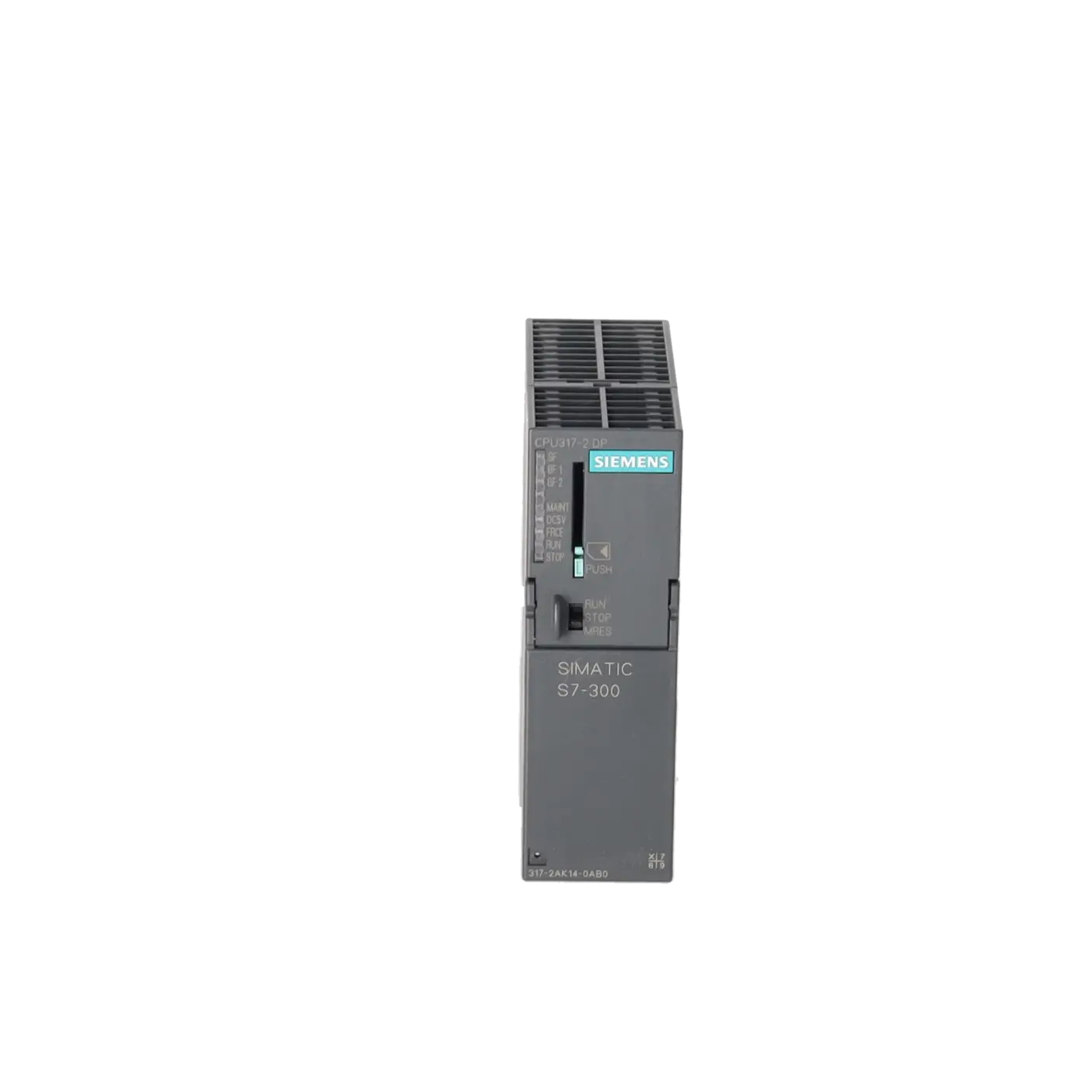
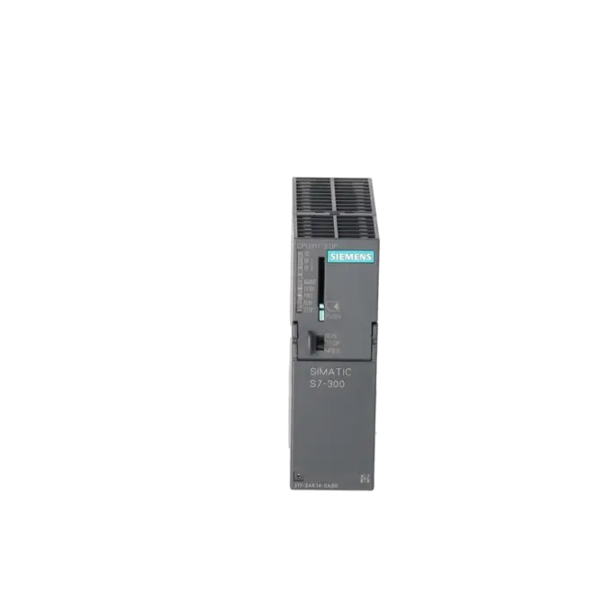
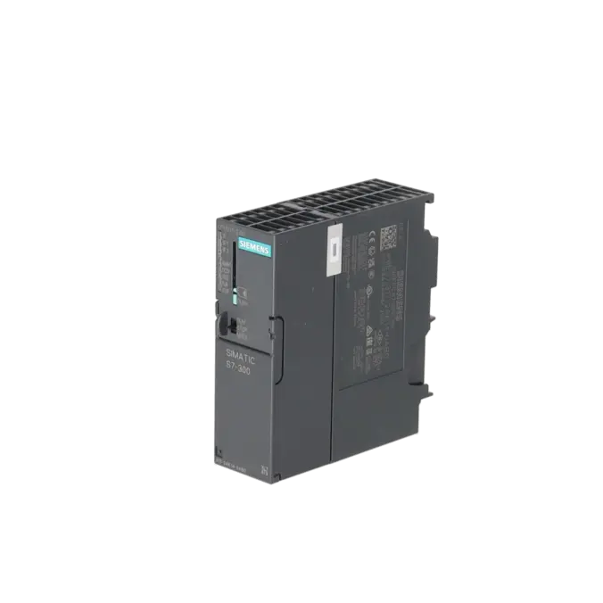
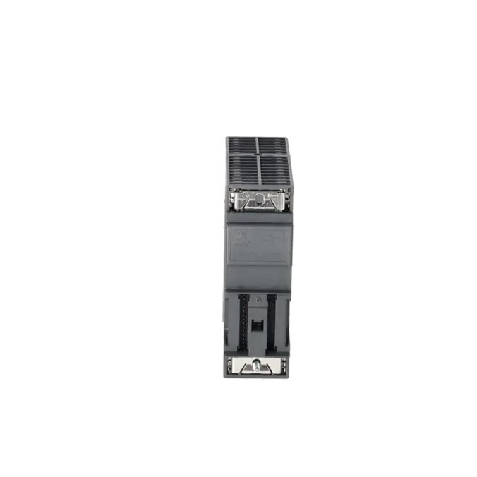
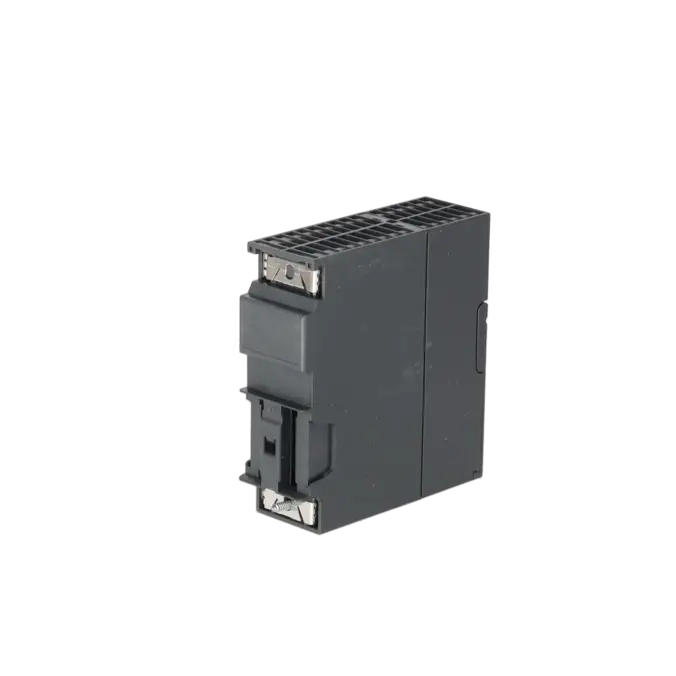
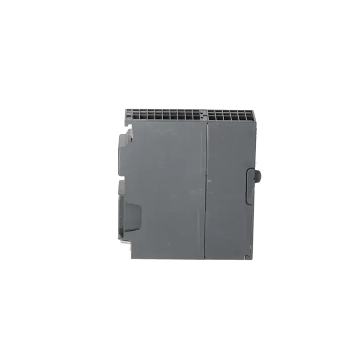
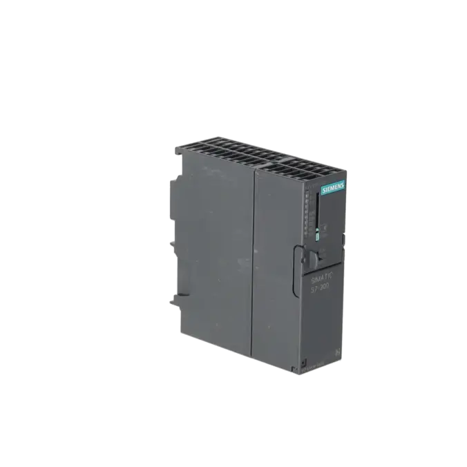
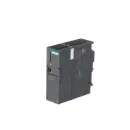
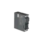
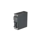
SIMATIC S7-300, CPU 317-2 DP, CENTRAL PROCESSING UNIT WITH 1 MB WORK MEMORY, 1ST INTERFACE MPI/DP 12 MBIT/S, 2ND INTERFACE DP MASTER/SLAVE MICRO MEMORY CARD REQUIRED
Services for SIEMENS 6ES7317-2AK14-0AB0
Repair
from 1.786,34 €
to 3.215,42 €
Replacement
2.258,95 €
1.694,21 €
Used
3.168,29 €
2.376,22 €
New
6.179,80 €
4.634,85 €
SIEMENS |
6ES7317-2AK14-0AB0 –
additional product information
| Delivery information | |||
|---|---|---|---|
| Export identifier | AL: N ECCN: EAR99H | ||
| Net weight | 0.401 | ||
| Quantity | 1 Stück | ||
| Packaging quantity | 1 | ||
| Additional product information | |||
|---|---|---|---|
| Product status | |||
| EAN | 4025515080183 | ||
| UPC | 040892788617 | ||
| Static lot number | 85371091 | ||
| List indicator | ST73 | ||
| Product group | 4256 | ||
| Country of origin | DE | ||
| Compliance with the substance restrictions according to RoHS directive | Since: 20110520 | ||
| Product classifications | Version | Classification | |
|---|---|---|---|
| eClass | 4 | / | |
| eClass | 5.1 | 27-24-22-07 | |
| eClass | 6.0 | 27-24-22-07 | |
| ETIM | 3 | / | |
| ETIM | 4 | EC000236 | |
| ETIM | 5 | EC000236 | |
What is 6ES7317-2AK14-0AB0 and where is it used?
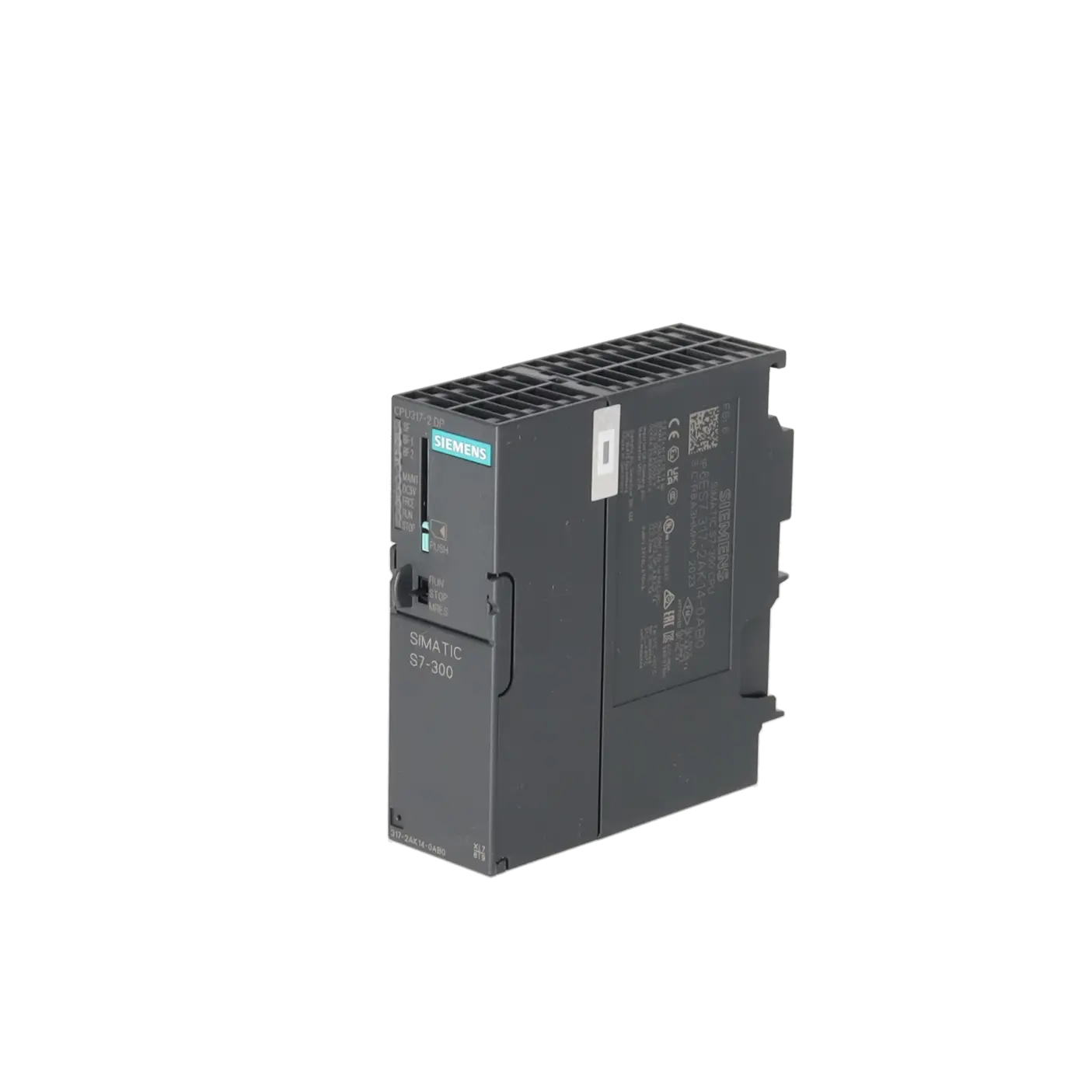
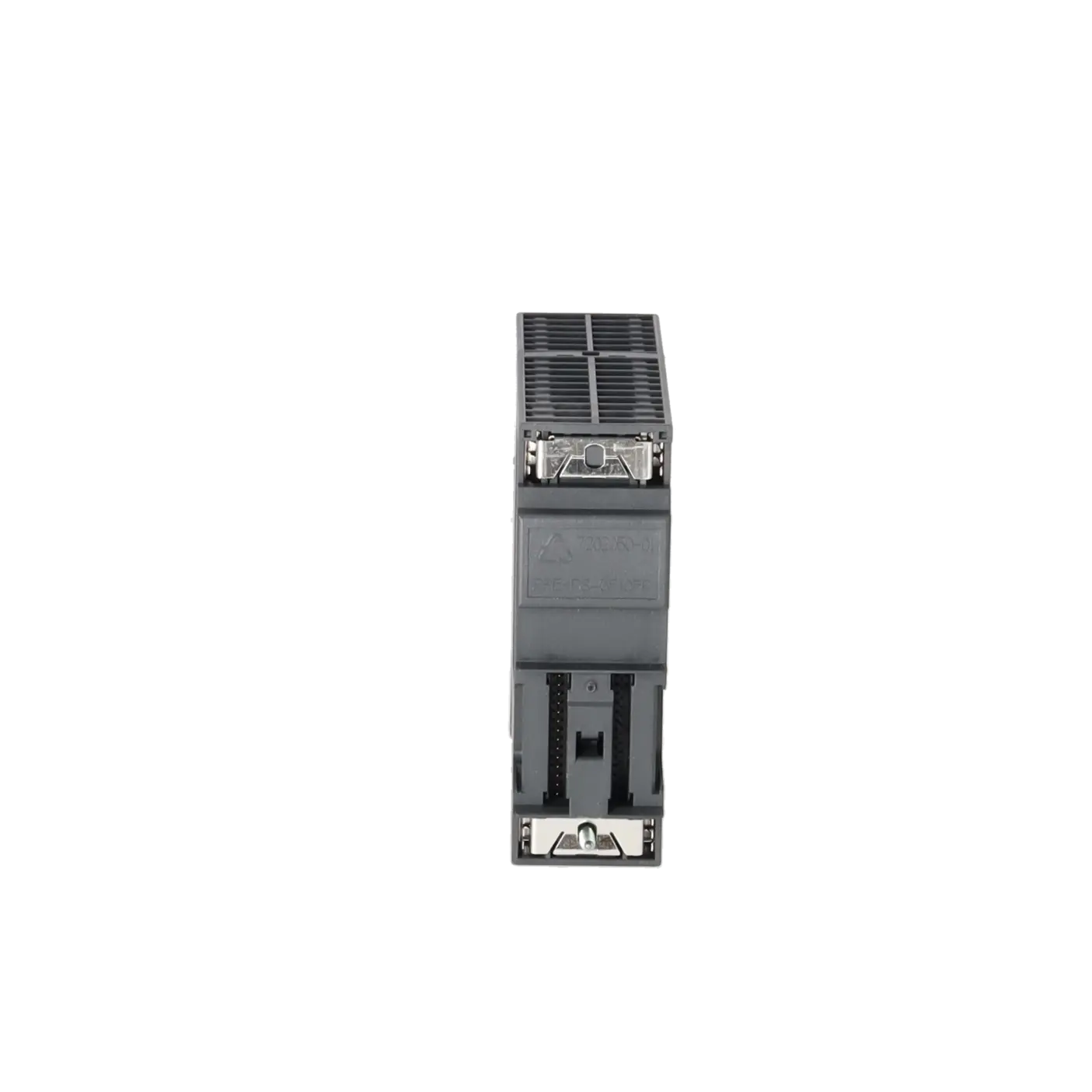
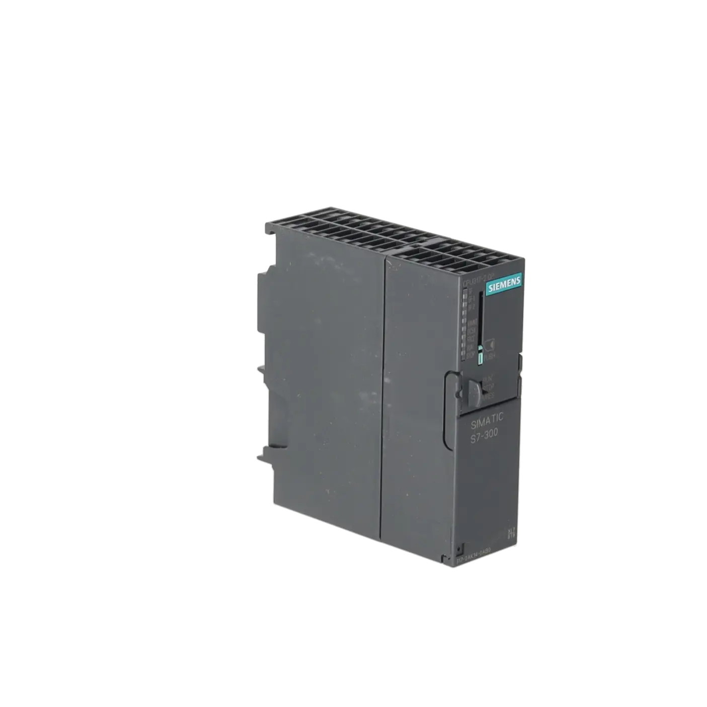
The 6ES7317-2AK14-0AB0 is a SIMATIC S7-300 CPU 317-2 DP from Siemens. It serves as the central processing assembly in modular S7-300 control systems and is intended for applications that require traditional STEP 7 projects, PROFIBUS DP communication, and robust integration into existing automation infrastructures. Typical areas of application include manufacturing systems, conveyor systems, packaging systems, and process systems, where existing racks, distributed I/O, and field devices are to remain in operation. The CPU provides 1 MB of work memory, an MPI/DP interface with 12 Mbit/s, and a second DP master/slave interface. A SIMATIC Micro Memory Card (MMC) is mandatory for operation.
Overview of the key technical data and what it means
Technically, the CPU is designed for 24 V DC and may be operated within a voltage range of 19.2 to 28.8 V DC, according to Siemens. The integrated 1,024 kB work memory cannot be expanded, while the user program is stored on the MMC, which can have a capacity of up to 8 MB. This is important for operators because the program, data retention, and restart behaviour depend directly on a functioning memory card. The CPU supports up to 124 DP devices per DP master interface, includes a diagnostic buffer with up to 500 entries, processes up to 65,536 digital channels, and is specified for operation between 0 and 60 °C. For maintenance personnel, this means extensive diagnostic capabilities, seamless integration into existing PROFIBUS networks, and sufficient performance reserves for more complex S7-300 applications.
Product status, life cycle status and obsolescence
Siemens lists the 6ES7317-2AK14-0AB0 as a spare part. Current Siemens sources also indicate that the product has been discontinued since 01/10/2025. For operators of existing S7-300 systems, this is a clear indication that the focus should no longer be on new installations but rather on spare parts availability, repair capability, and controlled inventory management. Within the S7-300 product range, Siemens designated the 6ES7317-2AK14-0AB0 as the successor to the older 6ES7317-2AJ10-0AB0. For modernisation projects, Siemens identifies the CPU 1516-3 PN/DP as a target platform in its migration guide. However, this is not a simple hardware replacement, but part of a broader migration to the S7-1500 platform.
Available EICHLER services and when they are relevant
Several options are available from EICHLER to ensure long-term availability of this CPU. Repair is suitable when the existing assembly is to remain at its current project status and an economical restoration is sufficient; the website specifies a turnaround time of 2 to 5 days. Exchange is the preferred option when downtime is critical, with a stated turnaround time of 1 to 3 days. In addition, used and new assemblies are available with short delivery times. For quality-critical applications, the optional test report is particularly relevant. For repairs, EICHLER also provides technical cleaning, preventive maintenance, comprehensive functional testing, and a minimum 24-month warranty. This helps ensure reliable operation even in an obsolescence management environment.
| Attribute | Value |
|---|---|
| General information | |
| Product type designation | CPU 317-2 DP |
| HW functional status | 1 |
| Firmware version | V3.3 |
| Engineering with | |
| ● Programming package | STEP 7 as of V5.5 + SP1 or STEP 7 V5.2 + SP1 or higher with HSP 202 |
| Supply voltage | |
| Rated value (DC) | 24 V |
| permissible range, lower limit (DC) | 19.2 V |
| permissible range, upper limit (DC) | 28.8 V |
| external protection for power supply lines (recommendation) | 2 A min. |
| Mains buffering | |
| ● Mains/voltage failure stored energy time | 5 ms |
| ● Repeat rate, min. | 1 s |
| Input current | |
| Current consumption (rated value) | 870 mA |
| Current consumption (in no-load operation), typ. | 120 mA |
| Inrush current, typ. | 4 A |
| I²t | 1 A²·s |
| Power loss | |
| Power loss, typ. | 4.5 W |
| Memory | |
| Work memory | |
| ● integrated | 1 024 kbyte |
| ● expandable | No |
| Load memory | |
| ● Plug-in (MMC) | Yes |
| ● Plug-in (MMC), max. | 8 Mbyte |
| ● Data management on MMC (after last programming), min. | 10 a |
| Backup | |
| ● present | Yes; Guaranteed by MMC (maintenance-free) |
| ● without battery | Yes; Program and data |
| CPU processing times | |
| for bit operations, typ. | 0.025 µs |
| for word operations, typ. | 0.03 µs |
| for fixed point arithmetic, typ. | 0.04 µs |
| for floating point arithmetic, typ. | 0.16 µs |
| CPU-blocks | |
| Number of blocks (total) | 2 048; (DBs, FCs, FBs); the maximum number of loadable blocks can be reduced by the MMC used. |
| DB | |
| ● Number, max. | 2 048; Number range: 1 to 16000 |
| ● Size, max. | 64 kbyte |
| FB | |
| ● Number, max. | 2 048; Number range: 0 to 7999 |
| ● Size, max. | 64 kbyte |
| FC | |
| ● Number, max. | 2 048; Number range: 0 to 7999 |
| ● Size, max. | 64 kbyte |
| OB | |
| ● Number, max. | see instruction list |
| ● Size, max. | 64 kbyte |
| ● Number of free cycle OBs | 1; OB 1 |
| ● Number of time alarm OBs | 1; OB 10 |
| ● Number of delay alarm OBs | 2; OB 20, 21 |
| ● Number of cyclic interrupt OBs | 4; OB 32, 33, 34, 35 |
| ● Number of process alarm OBs | 1; OB 40 |
| ● Number of DPV1 alarm OBs | 3; OB 55, 56, 57 |
| ● Number of isochronous mode OBs | 1; OB 61 |
| ● Number of startup OBs | 1; OB 100 |
| ● Number of asynchronous error OBs | 5; OB 80, 82, 85, 86, 87 |
| ● Number of synchronous error OBs | 2; OB 121, 122 |
| Nesting depth | |
| ● per priority class | 16 |
| ● additional within an error OB | 4 |
| Counters, timers and their retentivity | |
| S7 counter | |
| ● Number | 512 |
| Retentivity | |
| — adjustable | Yes |
| — preset | Z 0 to Z 7 |
| Counting range | |
| — lower limit | 0 |
| — upper limit | 999 |
| IEC counter | |
| ● present | Yes |
| ● Type | SFB |
| ● Number | Unlimited (limited only by RAM capacity) |
| S7 times | |
| ● Number | 512 |
| Retentivity | |
| — adjustable | Yes |
| — preset | No retentivity |
| Time range | |
| — lower limit | 10 ms |
| — upper limit | 9 990 s |
| IEC timer | |
| ● present | Yes |
| ● Type | SFB |
| ● Number | Unlimited (limited only by RAM capacity) |
| Data areas and their retentivity | |
| Retentive data area (incl. timers, counters, flags), max. | 256 kbyte |
| Flag | |
| ● Size, max. | 4 096 byte |
| ● Retentivity available | Yes; From MB 0 to MB 4 095 |
| ● Retentivity preset | MB 0 to MB 15 |
| ● Number of clock memories | 8; 1 memory byte |
| Data blocks | |
| ● Retentivity adjustable | Yes; via non-retain property on DB |
| ● Retentivity preset | Yes |
| Local data | |
| ● per priority class, max. | 32 768 byte; Max. 2048 bytes per block |
| Address area | |
| I/O address area | |
| ● Inputs | 8 192 byte |
| ● Outputs | 8 192 byte |
| of which distributed | |
| — Inputs | 8 192 byte |
| — Outputs | 8 192 byte |
| Process image | |
| ● Inputs | 8 192 byte |
| ● Outputs | 8 192 byte |
| ● Inputs, adjustable | 8 192 byte |
| ● Outputs, adjustable | 8 192 byte |
| ● Inputs, default | 256 byte |
| ● Outputs, default | 256 byte |
| Subprocess images | |
| ● Number of subprocess images, max. | 1 |
| Digital channels | |
| ● Inputs | 65 536 |
| — of which central | 1 024 |
| ● Outputs | 65 536 |
| — of which central | 1 024 |
| Analog channels | |
| ● Inputs | 4 096 |
| — of which central | 256 |
| ● Outputs | 4 096 |
| — of which central | 256 |
| Hardware configuration | |
| Number of expansion units, max. | 3 |
| Number of DP masters | |
| ● integrated | 2 |
| ● via CP | 4 |
| Number of operable FMs and CPs (recommended) | |
| ● FM | 8 |
| ● CP, PtP | 8 |
| ● CP, LAN | 10 |
| Rack | |
| ● Racks, max. | 4 |
| ● Modules per rack, max. | 8 |
| Time of day | |
| Clock | |
| ● Hardware clock (real-time) | Yes |
| ● retentive and synchronizable | Yes |
| ● Backup time | 6 wk; At 40 °C ambient temperature |
| ● Deviation per day, max. | 10 s; Typ.: 2 s |
| ● Behavior of the clock following POWER-ON | Clock continues running after POWER OFF |
| ● Behavior of the clock following expiry of backup period | the clock continues at the time of day it had when power was switched off |
| Operating hours counter | |
| ● Number | 4 |
| ● Number/Number range | 0 to 3 |
| ● Range of values | 0 to 2^31 hours (when using SFC 101) |
| ● Granularity | 1 h |
| ● retentive | Yes; Must be restarted at each restart |
| Clock synchronization | |
| ● supported | Yes |
| ● to MPI, master | Yes |
| ● on MPI, device | Yes |
| ● to DP, master | Yes; With DP slave only slave clock |
| ● on DP, device | Yes |
| ● in AS, master | Yes |
| ● in AS, device | Yes |
| ● on Ethernet via NTP | No |
| Digital inputs | |
| Number of digital inputs | 0 |
| Digital outputs | |
| Number of digital outputs | 0 |
| Analog inputs | |
| Number of analog inputs | 0 |
| Interfaces | |
| Number of PROFINET interfaces | 0 |
| Number of RS 485 interfaces | 2; Combined MPI / PROFIBUS DP and PROFIBUS DP |
| Number of RS 422 interfaces | 0 |
| 1. Interface | |
| Interface type | Integrated RS 485 interface |
| Isolated | Yes |
| Interface types | |
| ● RS 485 | Yes |
| ● Output current of the interface, max. | 200 mA |
| Protocols | |
| ● MPI | Yes |
| ● PROFIBUS DP master | Yes |
| ● PROFIBUS DP device | Yes; A DP slave at both interfaces simultaneously is not possible |
| ● Point-to-point connection | No |
| MPI | |
| ● Transmission rate, max. | 12 Mbit/s |
| Services | |
| — PG/OP communication | Yes |
| — Routing | Yes |
| — Global data communication | Yes |
| — S7 basic communication | Yes |
| — S7 communication | Yes; Only server, configured on one side |
| — S7 communication, as client | No; but via CP and loadable FB |
| — S7 communication, as server | Yes |
| PROFIBUS DP master | |
| ● Transmission rate, max. | 12 Mbit/s |
| ● max. number of DP devices | 124 |
| Services | |
| — PG/OP communication | Yes |
| — Routing | Yes |
| — Global data communication | No |
| — S7 basic communication | Yes; I blocks only |
| — S7 communication | Yes; Only server, configured on one side |
| — S7 communication, as client | No |
| — S7 communication, as server | Yes |
| — Equidistance | Yes |
| — Isochronous mode | No |
| — SYNC/FREEZE | Yes |
| — activation/deactivation of DP devices | Yes |
| — max. number of DP devices that can be activated/deactivated at the same time | 8 |
| — Direct data exchange (slave-to-slave communication) | Yes; as subscriber |
| — DPV1 | Yes |
| Address area | |
| — Inputs, max. | 8 kbyte |
| — Outputs, max. | 8 kbyte |
| User data per DP device | |
| — Inputs, max. | 244 byte |
| — Outputs, max. | 244 byte |
| PROFIBUS DP device | |
| ● Transmission rate, max. | 12 Mbit/s |
| ● automatic baud rate search | Yes; only with passive interface |
| ● Address area, max. | 32 |
| ● User data per address area, max. | 32 byte |
| Services | |
| — PG/OP communication | Yes |
| — Routing | Yes; Only with active interface |
| — Global data communication | No |
| — S7 basic communication | No |
| — S7 communication | Yes; Only server, configured on one side |
| — S7 communication, as client | No |
| — S7 communication, as server | Yes; Connection configured on one side only |
| — Direct data exchange (slave-to-slave communication) | Yes |
| — DPV1 | No |
| Transfer memory | |
| — Inputs | 244 byte |
| — Outputs | 244 byte |
| 2. Interface | |
| Interface type | Integrated RS 485 interface |
| Isolated | Yes |
| Interface types | |
| ● RS 485 | Yes |
| ● Output current of the interface, max. | 200 mA |
| Protocols | |
| ● MPI | No |
| ● PROFIBUS DP master | Yes |
| ● PROFIBUS DP device | Yes; A DP slave at both interfaces simultaneously is not possible |
| ● Point-to-point connection | No |
| PROFIBUS DP master | |
| ● Transmission rate, max. | 12 Mbit/s |
| ● max. number of DP devices | 124 |
| Services | |
| — PG/OP communication | Yes |
| — Routing | Yes |
| — Global data communication | No |
| — S7 basic communication | Yes; I blocks only |
| — S7 communication | Yes; Only server, configured on one side |
| — S7 communication, as client | No; but via CP and loadable FB |
| — S7 communication, as server | Yes |
| — Equidistance | Yes |
| — Isochronous mode | Yes; OB 61 |
| — SYNC/FREEZE | Yes |
| — activation/deactivation of DP devices | Yes |
| — max. number of DP devices that can be activated/deactivated at the same time | 8 |
| — Direct data exchange (slave-to-slave communication) | Yes; as subscriber |
| — DPV1 | Yes |
| Address area | |
| — Inputs, max. | 8 192 byte |
| — Outputs, max. | 8 192 byte |
| User data per DP device | |
| — Inputs, max. | 244 byte |
| — Outputs, max. | 244 byte |
| PROFIBUS DP device | |
| ● GSD file | The latest GSD file is available on the Internet (http://www.siemens.com/profibus-gsd) |
| ● Transmission rate, max. | 12 Mbit/s |
| ● automatic baud rate search | Yes; only with passive interface |
| ● Address area, max. | 32 |
| ● User data per address area, max. | 32 byte |
| Services | |
| — PG/OP communication | Yes |
| — Routing | Yes; Only with active interface |
| — Global data communication | No |
| — S7 basic communication | No |
| — S7 communication | Yes; Only server, configured on one side |
| — S7 communication, as client | No; but via CP and loadable FB |
| — S7 communication, as server | Yes |
| — Direct data exchange (slave-to-slave communication) | Yes |
| — DPV1 | No |
| Transfer memory | |
| — Inputs | 244 byte |
| — Outputs | 244 byte |
| Protocols | |
| PROFIsafe | No |
| Communication functions | |
| PG/OP communication | Yes |
| Data record routing | Yes |
| Global data communication | |
| ● supported | Yes |
| ● Number of GD loops, max. | 8 |
| ● Number of GD packets, max. | 8 |
| ● Number of GD packets, transmitter, max. | 8 |
| ● Number of GD packets, receiver, max. | 8 |
| ● Size of GD packets, max. | 22 byte |
| ● Size of GD packet (of which consistent), max. | 22 byte |
| S7 basic communication | |
| ● supported | Yes |
| ● User data per job, max. | 76 byte |
| ● User data per job (of which consistent), max. | 76 byte; 76 bytes (with X_SEND or X_RCV); 64 bytes (with X_PUT or X_GET as server) |
| S7 communication | |
| ● supported | Yes |
| ● as server | Yes |
| ● as client | Yes; Via CP and loadable FB |
| ● User data per job, max. | See online help of STEP 7 (shared parameters of the SFBs/FBs and of the SFCs/FCs of S7 Communication) |
| S5 compatible communication | |
| ● supported | Yes; via CP and loadable FC |
| Number of connections | |
| ● overall | 32 |
| ● usable for PG communication | 31 |
| — reserved for PG communication | 1 |
| — adjustable for PG communication, min. | 1 |
| — adjustable for PG communication, max. | 31 |
| ● usable for OP communication | 31 |
| — reserved for OP communication | 1 |
| — adjustable for OP communication, min. | 1 |
| — adjustable for OP communication, max. | 31 |
| ● usable for S7 basic communication | 30 |
| — reserved for S7 basic communication | 0 |
| — adjustable for S7 basic communication, min. | 0 |
| — adjustable for S7 basic communication, max. | 30 |
| ● usable for routing | X1 as a MPI, max. 10; X1 as DP Master max. 24; X1 as DP Slave (active) max. 14; X2 as DP Master max. 24; X2 as DP Slave (active) max. 14 |
| S7 message functions | |
| Number of login stations for message functions, max. | 32; Depending on the configured connections for PG/OP and S7 basic communication |
| Process diagnostic messages | Yes |
| simultaneously active Alarm_S blocks, max. | 300 |
| Test commissioning functions | |
| Status block | Yes; Up to 2 simultaneously |
| Single step | Yes |
| Number of breakpoints | 4 |
| Status/control | |
| ● Status/control variable | Yes |
| ● Variables | Inputs, outputs, memory bits, DB, times, counters |
| ● Number of variables, max. | 30 |
| — of which status variables, max. | 30 |
| — of which control variables, max. | 14 |
| Forcing | |
| ● Forcing | Yes |
| ● Forcing, variables | Inputs, outputs |
| ● Number of variables, max. | 10 |
| Diagnostic buffer | |
| ● present | Yes |
| ● Number of entries, max. | 500 |
| — adjustable | No |
| — of which powerfail-proof | 100; Only the last 100 entries are retained |
| ● Number of entries readable in RUN, max. | 499 |
| — adjustable | Yes; From 10 to 499 |
| — preset | 10 |
| Service data | |
| ● can be read out | Yes |
| Ambient conditions | |
| Ambient temperature during operation | |
| ● min. | 0 °C |
| ● max. | 60 °C |
| Configuration | |
| Configuration software | |
| ● STEP 7 | Yes; STEP 7 V5.5 + SP1 or higher or STEP 7 V5.3 + SP2 or higher with HSP 203 |
| ● STEP 7 Lite | No |
| Programming | |
| ● Command set | see instruction list |
| ● Nesting levels | 8 |
| ● System functions (SFC) | see instruction list |
| ● System function blocks (SFB) | see instruction list |
| Programming language | |
| — LAD | Yes |
| — FBD | Yes |
| — STL | Yes |
| — SCL | Yes |
| — CFC | Yes |
| — GRAPH | Yes |
| — HiGraph® | Yes |
| Know-how protection | |
| ● User program protection/password protection | Yes |
| ● Block encryption | Yes; With S7 block Privacy |
| Dimensions | |
| Width | 40 mm |
| Height | 125 mm |
| Depth | 130 mm |
| Weights | |
| Weight, approx. | 360 g |
| Fault description | Possible solution |
|---|---|
| Why is the BF1 LED on the CPU 317-2 DP lit red? | On the CPU 317-2 DP, the BF1 LED indicates a bus fault on interface X1. First check whether X1 has been correctly configured as MPI or PROFIBUS in STEP 7, whether the address and baud rate match the network, and whether the connectors, shielding, and terminating resistors are correctly installed. Then read out the diagnostic buffer. Particularly in the case of intermittent faults, it usually shows which device failed first or which device return was detected. |
| Why is the BF2 LED on the CPU 317-2 DP lit red? | The BF2 LED indicates a bus fault on interface X2. Typical causes include a missing or switched-off DP device, incorrect configuration of the second PROFIBUS segment, or a physical problem with the cable or bus connector. The recommended approach is to isolate the affected segment, check the terminating resistors, compare the actual network topology with the hardware configuration, and then read the diagnostic buffer. This helps determine whether the fault originates from the CPU, the network, or a field device. |
| Why is the SF LED lit and the CPU switching to STOP? | According to Siemens, the SF LED indicates a hardware or software fault. Common causes include an inconsistent hardware configuration, faulty wiring, a peripheral fault, or a program execution error that generates a diagnostic entry. After a memory reset, the CPU may also indicate SF if the configuration does not match the actual hardware setup. Therefore, the correct first step is not to replace components immediately but to read the diagnostic buffer. In most cases, it indicates whether the issue is a configuration error, assembly failure, bus fault, or program error. |
| Why does the CPU 317-2 DP not start or remain in STOP when no MMC is installed? | This CPU does not have an integrated load memory and requires a SIMATIC Micro Memory Card (MMC) for operation. If the card is missing, defective, or does not contain valid data, the CPU will not start normally. Therefore, first verify that a valid Siemens MMC is correctly inserted. If the card was removed during operation or its contents have become inconsistent, it may be necessary to reinsert it and perform a memory reset (MRES). Only then should the user program be downloaded again. |
| Why is the STOP LED flashing and the CPU requesting a memory reset? | A slowly flashing STOP LED indicates a memory reset request. This typically occurs after certain MMC operations, following a reset procedure, or when the memory is in an inconsistent state. In this case, the CPU is guided through the memory reset process using the MRES switch. If the CPU continues to behave abnormally afterwards, the MMC should be checked again or reformatted. If the SF indication remains active even without an MMC after the reset, a fault in the CPU or its firmware should also be considered. |
Is 6ES7317-2AK14-0AB0 still available?
Siemens classifies the assembly as a spare part and also states that the product has been discontinued since 01/10/2025. For operators, this means that procurement can no longer be considered within a normal product life cycle but must instead rely on remaining stock, exchange units, tested used assemblies, and repair services. This is precisely why offers including repair, exchange, and function-tested replacement units are particularly relevant for this CPU.
Which software is required for the 6ES7317-2AK14-0AB0?
Siemens specifies STEP 7 as the engineering and configuration environment for this CPU. The datasheet lists STEP 7 V5.5 + SP1 as the supported version, while older versions require the appropriate Support Package or Hotfix Support Package. For operators of legacy systems, this is important because not every older engineering installation can correctly recognise or configure the assembly without additional updates.
Which memory card does the CPU 317-2 DP require?
The CPU requires a SIMATIC Micro Memory Card (MMC) for operation. The MMC serves as the load memory, acts as a portable data carrier, and stores the program and data without requiring a battery. Siemens specifies an MMC capacity of up to 8 MB for this assembly. This is relevant for purchasing and maintenance because a missing or unsuitable memory card can directly lead to start-up problems or a complete system breakdown.
Is 6ES7317-2AK14-0AB0 the successor to 6ES7317-2AJ10-0AB0?
Yes. Siemens identifies the 6ES7317-2AK14-0AB0 as the successor to the older 6ES7317-2AJ10-0AB0. Siemens also describes the updated S7-300 V3 CPUs as spare-part compatible with their predecessor versions. In practice, this means that the 2AK14 variant is the most obvious procurement option when replacing a 2AJ10. Nevertheless, the specific project configuration and system environment should always be checked before installation.
For rapid recommissioning, which is more suitable: repair or exchange?
When downtime is the primary concern, an exchange unit is usually the fastest option, as EICHLER currently specifies a turnaround time of 1 to 3 days. If retaining the existing assembly is preferred and cost considerations are more important, repair is often the more economical solution; EICHLER specifies 2 to 5 days for this service. In addition, the repair process includes technical cleaning, preventive maintenance, functional testing, and a minimum 24-month warranty. For planned maintenance activities, this is often the most balanced solution.
Which modernisation option does Siemens recommend for this CPU?
For a genuine modernisation project, Siemens refers in its S7-300 to S7-1500 migration guide to the CPU 1516-3 PN/DP. This is important for decision-makers: the designation should be understood as a migration path, not as a direct hardware replacement. Siemens explicitly describes migration as a fundamental system change involving adaptations to hardware, software, and data transfer. For existing systems, the key decision is therefore whether to continue operation using a robust spare parts strategy or to implement a planned migration project.