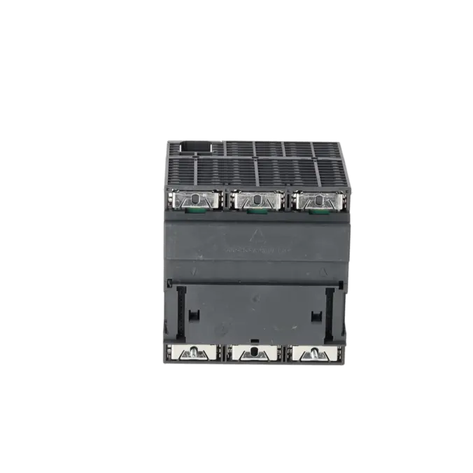
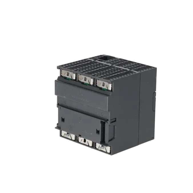
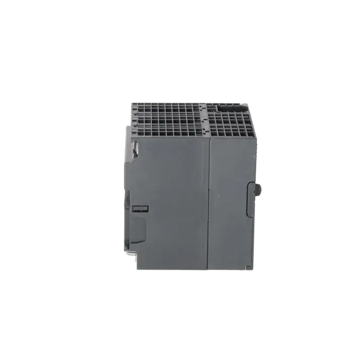
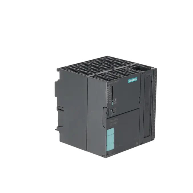
SIEMENS 6ES7315-7TJ10-0AB0
-
SIEMENS | PLC Controls | Central Processing Units
- EICHLER-art.no.: K0339817
- EAN: 4025515082552
- UPC: 887621438630
Product description
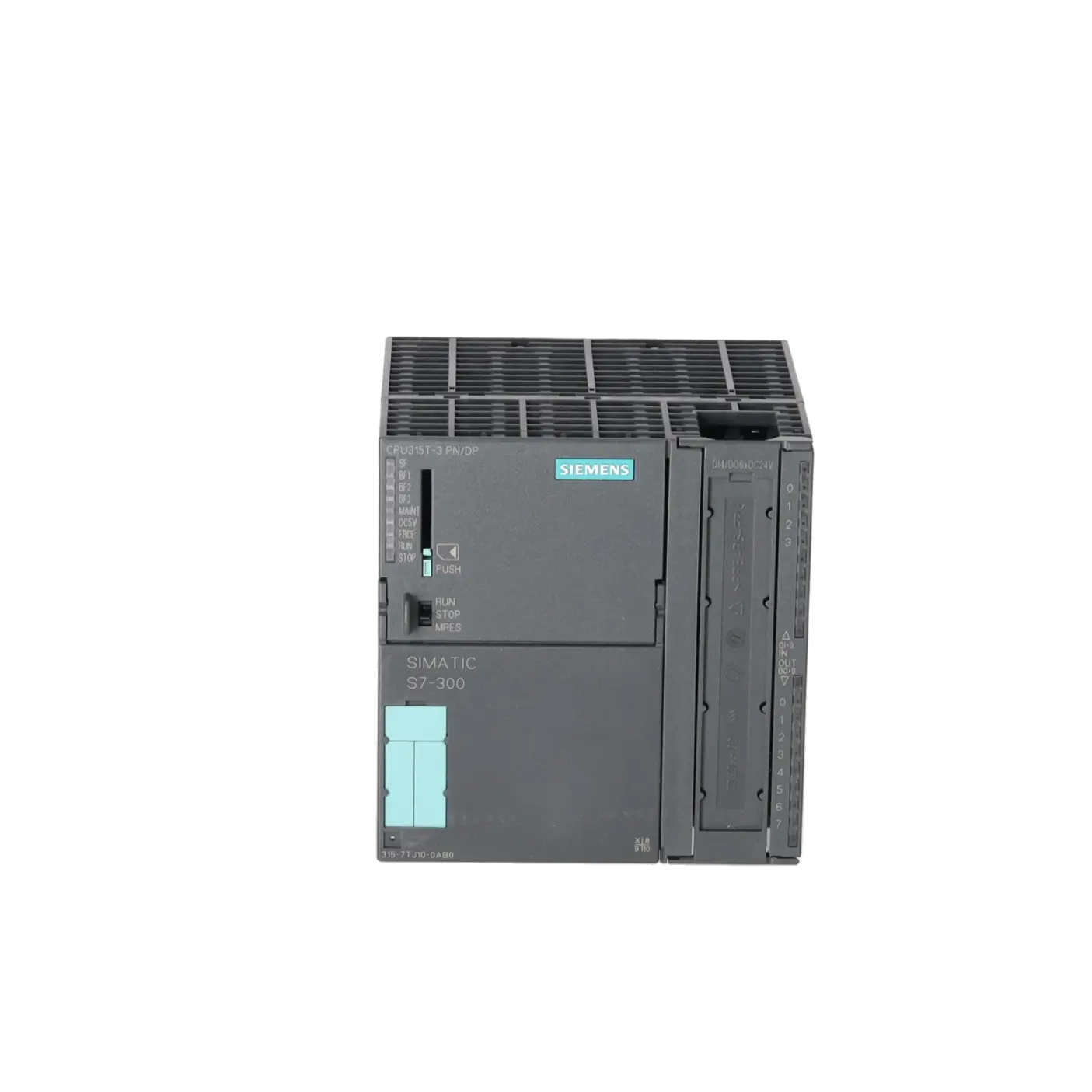
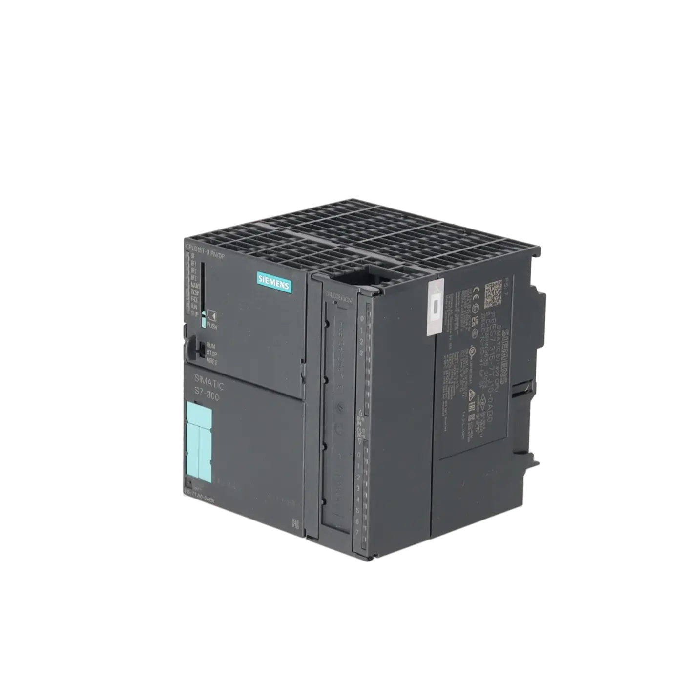
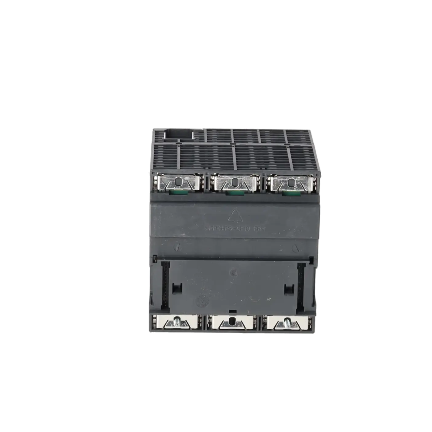
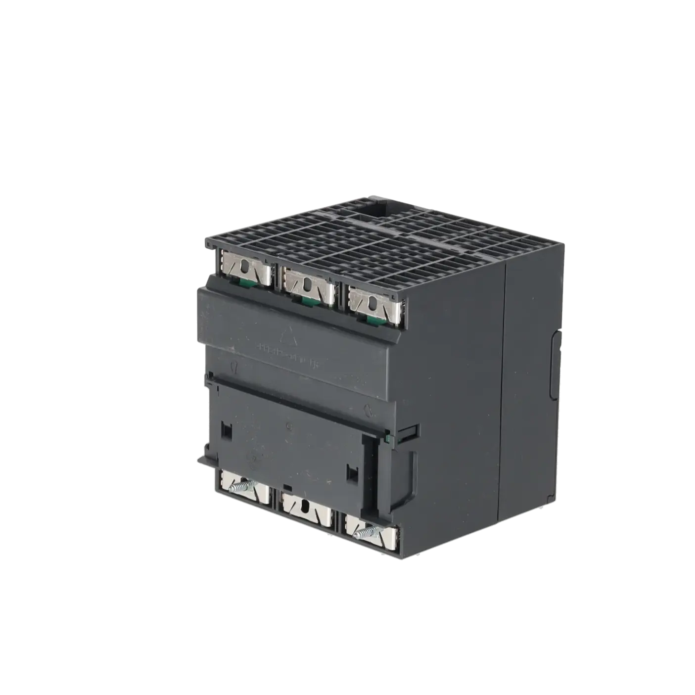
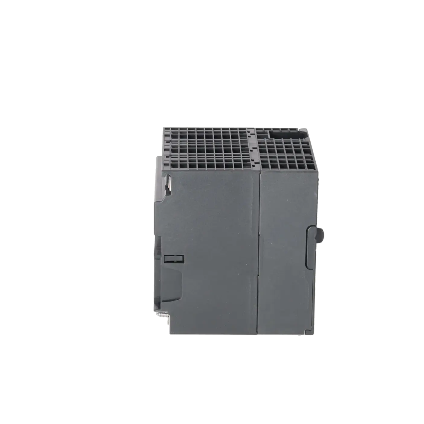
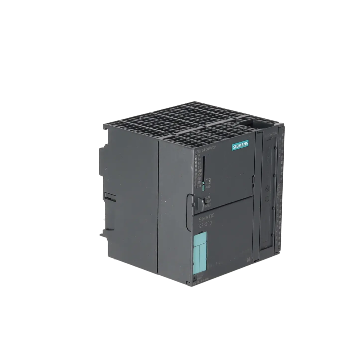
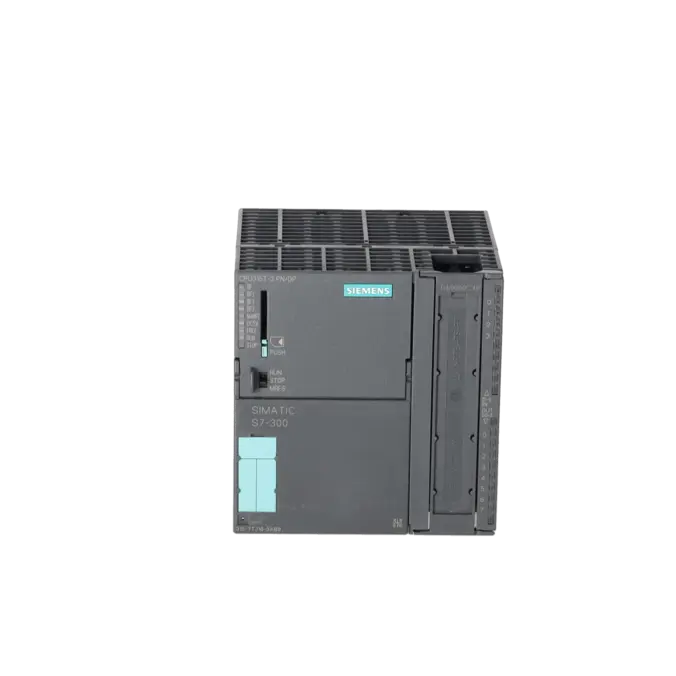
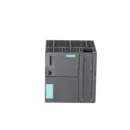
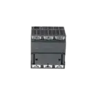
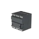
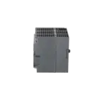
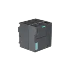
SIMATIC S7-300, CPU 315T-3 PN/DP, CENTRAL PROCESSING UNIT FOR PLC AND TECHNOLOGY TASKS, 384 KB WORK MEMORY, 1ST INTERFACE MPI/DP 12 MBIT/S, 2ND INTERFACE DP (DRIVE), 3RD INTERFACE ETHERNET PROFINET WITH 2-PORT SWITCH, INTEGR. I/O FOR TECHNOLOGY, FRONT CON
Services for SIEMENS 6ES7315-7TJ10-0AB0
Repair
from 1.324,47 €
to 2.139,52 €
Replacement
Used
New
5.094,10 €
3.820,57 €
SIEMENS |
6ES7315-7TJ10-0AB0 –
additional product information
| Delivery information | |||
|---|---|---|---|
| Export identifier | AL: N ECCN: EAR99H | ||
| Net weight | 0.718 | ||
| Quantity | 1 Stück | ||
| Packaging quantity | 1 | ||
| Additional product information | |||
|---|---|---|---|
| Product status | |||
| EAN | 4025515082552 | ||
| UPC | 887621438630 | ||
| Static lot number | 85371091 | ||
| List indicator | ST73 | ||
| Product group | 4256 | ||
| Country of origin | DE | ||
| Compliance with the substance restrictions according to RoHS directive | Since: 20130528 | ||
| Product classifications | Version | Classification | |
|---|---|---|---|
| eClass | 4 | / | |
| eClass | 5.1 | 27-24-22-07 | |
| eClass | 6.0 | 27-24-22-07 | |
| ETIM | 3 | / | |
| ETIM | 4 | EC000236 | |
| ETIM | 5 | EC000236 | |
What is the 6ES7315-7TJ10-0AB0 and where is it used?
The 6ES7315-7TJ10-0AB0 is a SIMATIC S7-300 CPU 315T-3 PN/DP from Siemens designed for both standard PLC tasks and integrated technology or motion-control applications. The module combines conventional control functions with features for drive technology, synchronous processing and high-speed switching signals. Typical applications include machines and systems with positioning tasks, cam controls, cam switching functions, reference point detection and synchronised motion sequences. For maintenance engineers, the CPU is particularly relevant when existing S7-300T applications must continue operating reliably. For purchasing departments, it is important whenever an identical order number is required for spare-part procurement, repair or exchange in order to minimise downtime without extensive re-engineering projects.
Overview of the most important technical data and what it means
The CPU operates on 24 V DC within a permissible range of 19.2 to 28.8 V. It provides 384 KB of work memory, an MPI/DP interface with up to 12 Mbit/s, a dedicated DP(DRIVE) interface for drive systems and a PROFINET interface with an integrated 2-port switch. For technology applications, it includes 4 integrated digital inputs and 8 integrated digital outputs. This is particularly important when processing reference cams, high-speed cam signals or drive-related signals with short response times. The CPU supports up to 8 axes and a total of 32 technology objects. For engineering and service purposes, STEP 7 V5.5 SP2 or later and the S7-Technology option package V4.2 SP3 or later are required. A Micro Memory Card with at least 8 MB capacity is mandatory.
Product status, life-cycle status and obsolescence
For this order number, Siemens lists the lifecycle status PM410 – Product Cancellation in the Industry Mall, with the product discontinued as of 01 October 2025. For operators of existing systems, this means the CPU remains technically relevant, but procurement becomes increasingly challenging over time because new units become less available and supply is increasingly dependent on remaining stock, repair services and qualified exchange concepts. It is also worth noting that the CPU 31xT-3 PN/DP historically replaced the older CPU 31xT-2 DP on a spare-parts-compatible basis. For modernisation projects, Siemens generally recommends migration to the S7-1500 platform as the successor system for the phased-out S7-300 family; however, this represents a migration project rather than a plug-compatible 1:1 replacement.
Available EICHLER services and their practical relevance
For the 6ES7315-7TJ10-0AB0, EICHLER offers repair, exchange, used units and new units. This is particularly valuable for maintenance and procurement teams when a system must be stabilised quickly without immediately committing to a complete migration project. Repair is especially suitable when the existing module is already fully integrated into the machine and downtime should be minimised by recommissioning with the existing project configuration. Benefits include technical cleaning, preventive maintenance, comprehensive functional testing and a minimum 24-month warranty. For processes requiring validation, an optional CPU/central module test report can provide additional technical assurance. Exchange, used and new units are particularly beneficial when time pressure, inventory strategy and obsolescence risks must all be considered simultaneously.
| Attribute | Value |
|---|---|
| General information | |
| Product type designation | CPU 315T-3 PN/DP |
| HW functional status | 1 |
| Firmware version | CPU: V3.2; integrated technology V4.1.5 |
| Product function | |
| ● Isochronous mode | Yes; Via PROFIBUS DP or PROFINET interface |
| Engineering with | |
| ● Programming package | STEP 7 V5.5 SP2 or higher and S7-Technology option package V4.2 SP3 |
| Supply voltage | |
| Rated value (DC) | 24 V |
| permissible range, lower limit (DC) | 19.2 V |
| permissible range, upper limit (DC) | 28.8 V |
| external protection for power supply lines (recommendation) | 2 A min. |
| Load voltage L+ | |
| ● Rated value (DC) | 24 V |
| ● Reverse polarity protection | Yes |
| Digital outputs | |
| — Rated value (DC) | 24 V; (2L+) |
| — Reverse polarity protection | No; (2L+) |
| Input current | |
| Current consumption (rated value) | 1 050 mA |
| Current consumption (in no-load operation), typ. | 230 mA |
| Inrush current, typ. | 6.5 A |
| I²t | 1 A²·s |
| Power loss | |
| Power loss, typ. | 7.5 W |
| Storage | |
| Work memory | |
| ● integrated | 384 kbyte |
| ● expandable | No |
| Load memory | |
| ● Plug-in (MMC) | Yes |
| ● Plug-in (MMC), max. | 8 Mbyte |
| ● Data management on MMC (after last programming), min. | 10 a |
| Backup | |
| ● present | Yes; Guaranteed by MMC (maintenance-free) |
| ● without battery | Yes; Program and data |
| CPU processing times | |
| for bit operations, typ. | 0.05 µs |
| for word operations, typ. | 0.09 µs |
| for fixed point arithmetic, typ. | 0.12 µs |
| for floating point arithmetic, typ. | 0.45 µs |
| CPU-blocks | |
| Number of blocks (total) | 1 024; (DBs, FCs, FBs); the maximum number of loadable blocks can be reduced by the MMC used. |
| DB | |
| ● Number, max. | 1 024; Number range: 1 to 16000 |
| ● Size, max. | 64 kbyte |
| FB | |
| ● Number, max. | 1 024; Number range: 0 to 7999 |
| ● Size, max. | 64 kbyte |
| FC | |
| ● Number, max. | 1 024; Number range: 0 to 7999 |
| ● Size, max. | 64 kbyte |
| OB | |
| ● Number, max. | see instruction list |
| ● Size, max. | 64 kbyte |
| ● Number of free cycle OBs | 1; OB 1 |
| ● Number of time alarm OBs | 1; OB 10 |
| ● Number of delay alarm OBs | 2; OB 20, 21 |
| ● Number of cyclic interrupt OBs | 4; OB 32, 33, 34, 35 |
| ● Number of process alarm OBs | 1; OB 40 |
| ● Number of DPV1 alarm OBs | 3; OB 55, 56, 57 |
| ● Number of isochronous mode OBs | 1; OB 61 - isochronous mode is possible either on DP or PROFINET IO (not simultaneously) |
| ● Number of technology synchronous alarm OBs | 1; OB 65 |
| ● Number of startup OBs | 1; OB 100 |
| ● Number of asynchronous error OBs | 6; OB 80, 82, 83, 85, 86, 87 (OB83 only for PROFINET IO) |
| ● Number of synchronous error OBs | 2; OB 121, 122 |
| Nesting depth | |
| ● per priority class | 16 |
| ● additional within an error OB | 4 |
| Counters, timers and their retentivity | |
| S7 counter | |
| ● Number | 256 |
| Retentivity | |
| — can be set | Yes |
| — preset | Z 0 to Z 7 |
| Counting range | |
| — can be set | Yes |
| — lower limit | 0 |
| — upper limit | 999 |
| IEC counter | |
| ● present | Yes |
| ● Type | SFB |
| ● Number | Unlimited (limited only by RAM capacity) |
| S7 timer | |
| ● Number | 256 |
| Retentivity | |
| — adjustable | Yes |
| — preset | No retentivity |
| Time range | |
| — lower limit | 10 ms |
| — upper limit | 9 990 s |
| IEC timer | |
| ● present | Yes |
| ● Type | SFB |
| ● Number | Unlimited (limited only by RAM capacity) |
| Data areas and their retentivity | |
| Retentive data area (incl. timers, counters, flags), max. | 128 kbyte |
| Flag | |
| ● Size, max. | 2 048 byte |
| ● Retentivity available | Yes; MB 0 to MB 2 047 |
| ● Retentivity preset | MB 0 to MB 15 |
| ● Number of clock memories | 8; 1 memory byte |
| Data blocks | |
| ● Retentivity adjustable | Yes; via non-retain property on DB |
| ● Retentivity preset | Yes |
| Local data | |
| ● per priority class, max. | 32 768 byte; Max. 2048 bytes per block |
| Address area | |
| I/O address area | |
| ● Inputs | 2 048 byte |
| ● Outputs | 2 048 byte |
| of which distributed | |
| — Inputs | 2 048 byte |
| — Outputs | 2 048 byte |
| Process image | |
| ● Inputs | 2 048 byte |
| ● Outputs | 2 048 byte |
| ● Inputs, adjustable | 2 048 byte |
| ● Outputs, adjustable | 2 048 byte |
| ● Inputs, default | 128 byte |
| ● Outputs, default | 128 byte |
| Subprocess images | |
| ● Number of subprocess images, max. | 1; With PROFINET IO, the length of the user data is limited to 1600 bytes |
| Digital channels | |
| ● Inputs | 16 384 |
| — of which central | 256 |
| ● Outputs | 16 384 |
| — of which central | 256 |
| Analog channels | |
| ● Inputs | 1 024 |
| — of which central | 64 |
| ● Outputs | 1 024 |
| — of which central | 64 |
| Hardware configuration | |
| Number of expansion units, max. | 0 |
| Number of DP masters | |
| ● integrated | 2; 1 DP and 1 DP (drive) |
| ● via CP | 2; for DP |
| Number of operable FMs and CPs (recommended) | |
| ● FM | 8 |
| ● CP, PtP | 8 |
| ● CP, LAN | 8 |
| Rack | |
| ● Racks, max. | 1 |
| ● Modules per rack, max. | 8 |
| Time of day | |
| Clock | |
| ● Hardware clock (real-time) | Yes |
| ● retentive and synchronizable | Yes |
| ● Backup time | 6 wk; At 40 °C ambient temperature |
| ● Deviation per day, max. | 10 s; Typ.: 2 s |
| ● Behavior of the clock following POWER-ON | Clock continues running after POWER OFF |
| ● Behavior of the clock following expiry of backup period | the clock continues at the time of day it had when power was switched off |
| Operating hours counter | |
| ● Number | 1 |
| ● Number/Number range | 0 |
| ● Range of values | 0 to 2^31 hours (when using SFC 101) |
| ● Granularity | 1 h |
| ● retentive | Yes; Must be restarted at each restart |
| Clock synchronization | |
| ● supported | Yes |
| ● to MPI, master | Yes |
| ● on MPI, device | Yes |
| ● to DP, master | Yes |
| ● on DP, device | Yes; Only time-of-day slave |
| ● in AS, master | Yes |
| ● in AS, device | Yes |
| ● on Ethernet via NTP | Yes; As client |
| Digital inputs | |
| Number of digital inputs | 4 |
| ● of which inputs usable for technological functions | 4 |
| Input characteristic curve in accordance with IEC 61131, type 1 | Yes |
| Number of simultaneously controllable inputs | |
| horizontal installation | |
| — up to 40 °C, max. | 4 |
| — up to 60 °C, max. | 4 |
| vertical installation | |
| — up to 40 °C, max. | 4 |
| Input voltage | |
| ● Rated value (DC) | 24 V |
| ● for signal "0" | -3 to +5V |
| ● for signal "1" | +15 to +30 V |
| Input current | |
| ● for signal "1", typ. | 7 mA |
| Input delay (for rated value of input voltage) | |
| for technological functions | |
| — at "0" to "1", max. | 10 µs; Typical |
| — at "1" to "0", max. | 10 µs; Typical |
| Cable length | |
| ● shielded, max. | 1 000 m |
| Digital outputs | |
| Number of digital outputs | 8 |
| ● of which high-speed outputs | 8 |
| Functions | for technology functions, e.g. high-speed cam switch signals |
| Short-circuit protection | Yes |
| ● Response threshold, typ. | 1 A |
| Limitation of inductive shutdown voltage to | 48 V |
| Controlling a digital input | No |
| Switching capacity of the outputs | |
| ● on lamp load, max. | 5 W |
| Load resistance range | |
| ● lower limit | 48 Ω |
| ● upper limit | 4 kΩ |
| Output voltage | |
| ● for signal "0", max. | 3 V; (2L+) |
| ● for signal "1", min. | Rated voltage -2.5 V |
| Output current | |
| ● for signal "1" rated value | 0.5 A |
| ● for signal "1" permissible range for 0 to 60 °C, min. | 5 mA |
| ● for signal "1" permissible range for 0 to 60 °C, max. | 0.6 A |
| ● for signal "0" residual current, max. | 0.3 mA |
| Parallel switching of two outputs | |
| ● for uprating | No |
| ● for redundant control of a load | No |
| Switching frequency | |
| ● with resistive load, max. | 100 Hz |
| ● with inductive load, max. | 0.2 Hz; According to IEC 60947-5-1, DC-13 |
| ● on lamp load, max. | 100 Hz |
| Total current of the outputs (per group) | |
| horizontal installation | |
| — up to 40 °C, max. | 4 A |
| — up to 60 °C, max. | 3 A |
| all other mounting positions | |
| — up to 40 °C, max. | 4 A |
| Integrated high-speed cams | |
| ● Switching accuracy (+/-) | 70 µs |
| Cable length | |
| ● shielded, max. | 1 000 m |
| Analog inputs | |
| Number of analog inputs | 0 |
| Encoder | |
| Connectable encoders | |
| ● 2-wire sensor | No |
| Interfaces | |
| Number of PROFINET interfaces | 1 |
| Number of RS 485 interfaces | 2 |
| Number of RS 422 interfaces | 0 |
| 1. Interface | |
| Interface type | Integrated RS 485 interface |
| Isolated | Yes |
| Interface types | |
| ● RS 485 | Yes |
| ● Output current of the interface, max. | 200 mA |
| Protocols | |
| ● MPI | Yes |
| ● PROFIBUS DP master | Yes |
| ● PROFIBUS DP device | Yes |
| ● Point-to-point connection | No |
| MPI | |
| ● Transmission rate, max. | 12 Mbit/s |
| Services | |
| — PG/OP communication | Yes |
| — Routing | Yes |
| — Global data communication | Yes |
| — S7 basic communication | Yes |
| — S7 communication | Yes |
| — S7 communication, as client | No; but via CP and loadable FB |
| — S7 communication, as server | Yes |
| PROFIBUS DP master | |
| ● Transmission rate, max. | 12 Mbit/s |
| ● max. number of DP devices | 124 |
| Services | |
| — PG/OP communication | Yes |
| — Routing | Yes |
| — Global data communication | No |
| — S7 basic communication | Yes; I blocks only |
| — S7 communication | Yes |
| — S7 communication, as client | No |
| — S7 communication, as server | Yes |
| — Equidistance | Yes |
| — Isochronous mode | Yes; OB 61; isochronous mode can only be used alternatively on PROFIBUS DP or PROFINET IO |
| — SYNC/FREEZE | Yes |
| — activation/deactivation of DP devices | Yes |
| — max. number of DP devices that can be activated/deactivated at the same time | 8 |
| — Direct data exchange (slave-to-slave communication) | Yes; as subscriber |
| — DPV1 | Yes |
| Address area | |
| — Inputs, max. | 2 kbyte |
| — Outputs, max. | 2 kbyte |
| User data per DP device | |
| — Inputs, max. | 244 byte |
| — Outputs, max. | 244 byte |
| PROFIBUS DP device | |
| ● Transmission rate, max. | 12 Mbit/s |
| ● automatic baud rate search | Yes; only with passive interface |
| ● Address area, max. | 32 |
| ● User data per address area, max. | 32 byte |
| Services | |
| — PG/OP communication | Yes |
| — Routing | Yes; Only with active interface |
| — Global data communication | No |
| — S7 basic communication | No |
| — S7 communication | Yes |
| — S7 communication, as client | No |
| — S7 communication, as server | Yes; Connection configured on one side only |
| — Direct data exchange (slave-to-slave communication) | Yes |
| — DPV1 | No |
| Transfer memory | |
| — Inputs | 244 byte |
| — Outputs | 244 byte |
| 2. Interface | |
| Interface type | Integrated RS 485 interface |
| Isolated | Yes |
| Interface types | |
| ● RS 485 | Yes |
| ● Output current of the interface, max. | 200 mA |
| Protocols | |
| ● MPI | No |
| ● PROFIBUS DP master | Yes; DP(DRIVE)-Master |
| ● PROFIBUS DP device | No |
| ● Point-to-point connection | No |
| PROFIBUS DP master | |
| ● Transmission rate, max. | 12 Mbit/s |
| ● max. number of DP devices | 64 |
| Services | |
| — PG/OP communication | No |
| — Routing | No |
| — Global data communication | No |
| — S7 basic communication | No |
| — S7 communication | No |
| — Equidistance | Yes |
| — Isochronous mode | Yes |
| — SYNC/FREEZE | No |
| — activation/deactivation of DP devices | Yes |
| — DPV1 | No |
| Address area | |
| — Inputs, max. | 1 024 byte |
| — Outputs, max. | 1 024 byte |
| User data per DP device | |
| — Inputs, max. | 244 byte |
| — Outputs, max. | 244 byte |
| PROFIBUS DP device | |
| ● GSD file | http://support.automation.siemens.com in Product Support area |
| ● Transmission rate, max. | 12 Mbit/s |
| 3. Interface | |
| Interface type | PROFINET |
| Isolated | Yes |
| automatic detection of transmission rate | Yes; 10/100 Mbit/s |
| Autonegotiation | Yes |
| Autocrossing | Yes |
| Change of IP address at runtime, supported | Yes |
| Interface types | |
| ● RJ 45 (Ethernet) | Yes |
| ● Number of ports | 2 |
| ● integrated switch | Yes |
| Protocols | |
| ● MPI | No |
| ● PROFINET IO Controller | Yes; Also simultaneously with IO-Device functionality |
| ● PROFINET IO device | Yes; Also simultaneously with IO Controller functionality |
| ● PROFIBUS DP master | No |
| ● PROFIBUS DP device | No |
| ● Open IE communication | Yes; Via TCP/IP, ISO on TCP, and UDP |
| ● Web server | Yes |
| ● Media redundancy | Yes |
| PROFINET IO Controller | |
| ● Transmission rate, max. | 100 Mbit/s |
| Services | |
| — PG/OP communication | Yes |
| — Routing | Yes |
| — S7 communication | Yes; With loadable FBs, max. configurable connections: 14, max. number of instances: 32 |
| — Isochronous mode | Yes; OB 61; isochronous mode can only be used alternatively on PROFIBUS DP or PROFINET IO |
| — Shared device | Yes |
| — Prioritized startup | Yes |
| — Number of IO devices with prioritized startup, max. | 32 |
| — Number of connectable IO Devices, max. | 128 |
| — Of which IO devices with IRT, max. | 64 |
| — of which in line, max. | 64 |
| — Number of connectable IO Devices for RT, max. | 128 |
| — of which in line, max. | 128 |
| — Activation/deactivation of IO Devices | Yes |
| — Number of IO Devices that can be simultaneously activated/deactivated, max. | 8 |
| — IO Devices changing during operation (partner ports), supported | Yes |
| — Number of IO Devices per tool, max. | 8 |
| — Device replacement without swap medium | Yes |
| — Send cycles | 250 µs, 500 µs, 1 ms, 2 ms, 4 ms |
| — Updating time | 250 µs to 512 ms (depending on the operating mode, see Manual "S7-300 CPU 31xC and CPU 31x, technical Data" for more details) |
| Address area | |
| — Inputs, max. | 2 kbyte |
| — Outputs, max. | 2 kbyte |
| — User data consistency, max. | 1 024 byte |
| PROFINET IO Device | |
| Services | |
| — PG/OP communication | Yes |
| — Routing | Yes |
| — S7 communication | Yes; With loadable FBs, max. configurable connections: 14, max. number of instances: 32 |
| — Isochronous mode | No |
| — IRT | Yes |
| — PROFIenergy | Yes; With SFB 73 / 74 prepared for loadable PROFIenergy standard FB for I-Device |
| — Shared device | Yes |
| — Number of IO Controllers with shared device, max. | 2 |
| Transfer memory | |
| — Inputs, max. | 1 440 byte; Per IO Controller with shared device |
| — Outputs, max. | 1 440 byte; Per IO Controller with shared device |
| Submodules | |
| — Number, max. | 64 |
| — User data per submodule, max. | 1 024 byte |
| Open IE communication | |
| ● Number of connections, max. | 8 |
| ● Local port numbers used at the system end | 0, 20, 21, 23, 25, 80, 102, 135, 161, 443, 8080, 34962, 34963, 34964, 65532, 65533, 65534, 65535 |
| ● Keep-alive function, supported | Yes |
| Protocols | |
| PROFIsafe | No |
| Redundancy mode | |
| Media redundancy | |
| — Switchover time on line break, typ. | 200 ms; PROFINET MRP |
| — Number of stations in the ring, max. | 50 |
| Open IE communication | |
| ● TCP/IP | Yes; via integrated PROFINET interface and loadable FBs |
| — Number of connections, max. | 8 |
| — Data length for connection type 01H, max. | 1 460 byte |
| — Data length for connection type 11H, max. | 32 768 byte |
| — several passive connections per port, supported | Yes |
| ● ISO-on-TCP (RFC1006) | Yes; via integrated PROFINET interface and loadable FBs |
| — Number of connections, max. | 8 |
| — Data length, max. | 32 768 byte |
| ● UDP | Yes; via integrated PROFINET interface and loadable FBs |
| — Number of connections, max. | 8 |
| — Data length, max. | 1 472 byte |
| Web server | |
| ● supported | Yes |
| ● User-defined websites | Yes |
| ● Number of HTTP clients | 5 |
| Communication functions | |
| PG/OP communication | Yes |
| Data record routing | Yes |
| Global data communication | |
| ● supported | Yes |
| ● Number of GD loops, max. | 8 |
| ● Number of GD packets, max. | 8 |
| ● Number of GD packets, transmitter, max. | 8 |
| ● Number of GD packets, receiver, max. | 8 |
| ● Size of GD packets, max. | 22 byte |
| ● Size of GD packet (of which consistent), max. | 22 byte |
| S7 basic communication | |
| ● supported | Yes |
| ● User data per job, max. | 76 byte |
| ● User data per job (of which consistent), max. | 76 byte; 76 bytes (with X_SEND or X_RCV); 64 bytes (with X_PUT or X_GET as server) |
| S7 communication | |
| ● supported | Yes |
| ● as server | Yes |
| ● as client | Yes; via integrated PROFINET interface and loadable FB or via CP and loadable FB |
| ● User data per job, max. | See online help of STEP 7 (shared parameters of the SFBs/FBs and of the SFCs/FCs of S7 Communication) |
| S5 compatible communication | |
| ● supported | Yes; via CP and loadable FC |
| Number of connections | |
| ● overall | 16 |
| ● usable for PG communication | 15 |
| — reserved for PG communication | 1 |
| — adjustable for PG communication, min. | 1 |
| — adjustable for PG communication, max. | 15 |
| ● usable for OP communication | 15 |
| — reserved for OP communication | 1 |
| — adjustable for OP communication, min. | 1 |
| — adjustable for OP communication, max. | 15 |
| ● usable for S7 basic communication | 14 |
| — reserved for S7 basic communication | 0 |
| — adjustable for S7 basic communication, min. | 0 |
| — adjustable for S7 basic communication, max. | 14 |
| ● usable for S7 communication | 14 |
| — reserved for S7 communication | 0 |
| — adjustable for S7 communication, min. | 0 |
| — adjustable for S7 communication, max. | 14 |
| ● total number of instances, max. | 32 |
| ● usable for routing | X1 as MPI: max. 10; X1 as DP master: max. 24; X1 as DP slave (active): max. 14; X2 as PROFINET: 24 max. |
| S7 message functions | |
| Number of login stations for message functions, max. | 16; Depending on the configured connections for PG/OP and S7 basic communication |
| Process diagnostic messages | Yes |
| simultaneously active Alarm_S blocks, max. | 300 |
| Test commissioning functions | |
| Status block | Yes; Up to 2 simultaneously |
| Single step | Yes |
| Number of breakpoints | 4; without continuation |
| Status/control | |
| ● Status/control variable | Yes |
| ● Variables | Inputs, outputs, memory bits, DB, times, counters |
| ● Number of variables, max. | 30 |
| — of which status variables, max. | 30 |
| — of which control variables, max. | 14 |
| Forcing | |
| ● Forcing | Yes |
| ● Forcing, variables | Inputs, outputs |
| ● Number of variables, max. | 10 |
| Diagnostic buffer | |
| ● present | Yes |
| ● Number of entries, max. | 500 |
| — can be set | No |
| — of which powerfail-proof | 100; Only the last 100 entries are retained |
| ● Number of entries readable in RUN, max. | 499 |
| — can be set | Yes; From 10 to 499 |
| — preset | 10 |
| Service data | |
| ● Can be read out | Yes |
| Interrupts/diagnostics/status information | |
| Alarms | No |
| Diagnostics function | No |
| Diagnostics indication LED | |
| ● Status indicator digital input (green) | Yes |
| ● Status indicator digital output (green) | Yes |
| Potential separation | |
| Potential separation digital inputs | |
| ● between the channels and backplane bus | Yes |
| Potential separation digital outputs | |
| ● between the channels and backplane bus | Yes |
| Isolation | |
| Isolation tested with | 500 V DC |
| Ambient conditions | |
| Ambient temperature during operation | |
| ● min. | 0 °C |
| ● max. | 60 °C |
| Configuration | |
| Configuration software | |
| ● STEP 7 | Yes; STEP 7 V5.5 SP2 or higher and S7-Technology option package V4.2 SP3 |
| Programming | |
| ● Command set | see instruction list |
| ● Nesting levels | 8 |
| ● System functions (SFC) | see instruction list |
| ● System function blocks (SFB) | see instruction list |
| Programming language | |
| — LAD | Yes |
| — FBD | Yes |
| — STL | Yes |
| — SCL | Yes |
| — CFC | Yes |
| — GRAPH | Yes |
| — HiGraph® | Yes |
| Know-how protection | |
| ● User program protection/password protection | Yes |
| ● Block encryption | Yes; With S7 block Privacy |
| Dimensions | |
| Width | 120 mm |
| Height | 125 mm |
| Depth | 130 mm |
| Weights | |
| Weight, approx. | 640 g |
| Fault description | Possible solution |
|---|---|
| Why does the STOP LED flash when the MMC is inserted and the CPU does not switch to RUN? | In this condition, the CPU is requesting a memory reset (MRES). First check whether a suitable Micro Memory Card (MMC) is installed. Then perform the Siemens-recommended MRES/memory reset procedure correctly and reload the hardware configuration and user program. If the behaviour persists with the same card, the MMC should be formatted or replaced and the diagnostic buffer should be checked. |
| Why can't I find 6ES7315-7TJ10-0AB0 in the STEP 7 hardware catalogue? | For this technology CPU, a standard hardware profile is not sufficient. In HW Config, the SIMATIC Technology CPU profile must be used. In addition, a compatible version of S7-Technology must be installed. Siemens specifies STEP 7 V5.5 SP2 or later and S7-Technology V4.2 SP3 or later for engineering. If this package is missing or outdated, the CPU may not appear in the catalogue or may not be displayed correctly. |
| Why is the BF3 LED lit or flashing on the CPU 315T-3 PN/DP? | BF3 indicates a fault on the DP(DRIVE) interface X3. Common causes include bus faults, interrupted cabling, incorrectly configured bus connectors, an unreachable slave, or incorrect project configuration and parameter assignment. Check the cables, connectors, addresses, slave availability and hardware configuration. If the CPU is running in RUN mode, also verify that OB86 is present so that communication faults do not unnecessarily force the CPU into STOP mode. |
| Why are the SF or MAINT LEDs active and the PROFINET communication appears unstable? | On this CPU, this may indicate a loss of synchronisation within the PROFINET IO system, failure of a sync master, maintenance requests such as excessive attenuation on fibre-optic links, or faults within an MRP ring topology. Check the status of the PROFINET devices, the ring connection, the sync master configuration and the affected devices in the diagnostics. In particular, for isochronous or synchronised applications, the network structure must exactly match the project configuration. |
| Why does the CPU report Z1=8022 or fail during an alarm storm? | Siemens describes a behaviour in older firmware versions where an alarm storm can lead to a fault with the diagnostic code Z1=8022. The recommended solution is to update the firmware to a newer approved version. Siemens identifies relevant corrections from Firmware V3.2.14 onwards, while Firmware V3.2.19 is also listed for this CPU. Before carrying out a firmware update, verify the project status, engineering software version and ensure that a complete backup of the existing installation is available. |
Is the 6ES7315-7TJ10-0AB0 still available or has it been discontinued?
Siemens lists the module with the lifecycle status PM410 – Product Cancellation and specifies 01 October 2025 as the product discontinuation date. For operators, this does not automatically mean that supply is no longer possible. In practice, however, repair, exchange services, used equipment and strategic spare-parts stocking become significantly more important because the availability of new units gradually decreases over time. For critical machines, it is therefore not only the part number that matters, but also a reliable service strategy to protect against unplanned downtime.
Which memory card is required for the CPU 315T-3 PN/DP?
The CPU requires a SIMATIC Micro Memory Card (MMC) because no integrated load memory is provided. For full functionality, Siemens specifies a minimum capacity of 8 MB. This is particularly important during procurement, as MMC-related issues frequently lead to commissioning problems, STOP requests or incomplete functionality. Anyone stocking a spare CPU should therefore also keep a suitable MMC available in order to avoid unnecessary delays during replacement.
Which software is required for engineering, diagnostics and service?
Siemens specifies STEP 7 V5.5 SP2 or later together with the S7-Technology option package V4.2 SP3 or later for this CPU. This is important not only for initial engineering but also for service activities such as hardware replacement, diagnostics, firmware maintenance and opening existing projects. In HW Config, the correct SIMATIC Technology CPU profile must also be selected. Without this environment, typical problems occur: the CPU may not appear in the hardware catalogue, technology objects may be unavailable, or service access may be limited.
Can the 6ES7315-7TJ10-0AB0 replace older 315T variants?
Yes. Siemens describes the CPU 31xT-3 PN/DP as a spare-parts-compatible successor to the CPU 31xT-2 DP. Siemens documentation also records the migration from the older order number 6ES7315-6TH13-0AB0 to 6ES7315-7TJ10-0AB0. This is particularly beneficial for operators of older motion-control systems because existing machines can often be kept operational with significantly less effort than would be required for a complete platform migration. Nevertheless, firmware version, project configuration, interface assignments and the technology configuration should always be checked before replacement.
Which motion-control applications is this CPU particularly suited for?
The CPU is designed for machine applications with integrated technology functions and supports up to 8 axes and a total of 32 technology objects, including axes, cams, cam tracks, measuring probes and external encoders. It also provides 4 integrated digital inputs and 8 integrated digital outputs for technology functions such as reference-point detection and high-speed cam switching signals. This makes the CPU especially suitable for existing installations where PLC logic and drive-related motion functions are combined within a single controller.
Is the S7-1500 a direct successor to this CPU?
Siemens identifies the S7-1500 family as the successor platform to the discontinued S7-300 range. However, this should be understood correctly from a technical perspective: it represents a migration path, not a plug-compatible replacement for the 6ES7315-7TJ10-0AB0. If avoiding immediate downtime is the priority, repair, exchange or procurement of an identical replacement unit is usually the faster option. For long-term reduction of obsolescence risks, modernisation of the engineering environment and future-proof spare-parts strategies, a planned migration to the S7-1500 platform should be considered.