


SIEMENS 6ES7315-6FF04-0AB0
-
SIEMENS | PLC Controls | Central Processing Units
- EICHLER-art.no.: K0226850
- EAN: 4025515077756
- UPC: 040892550320
Product description
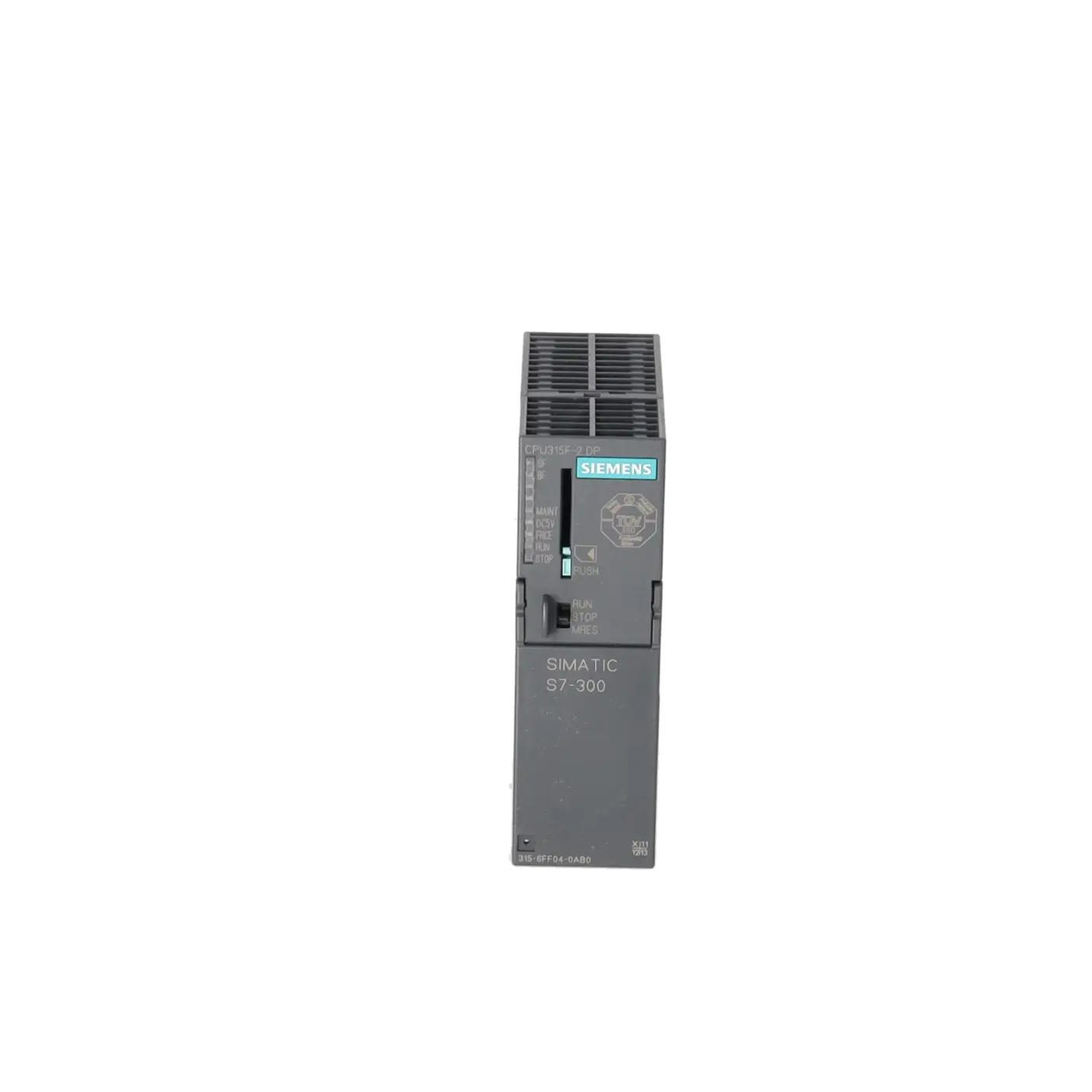
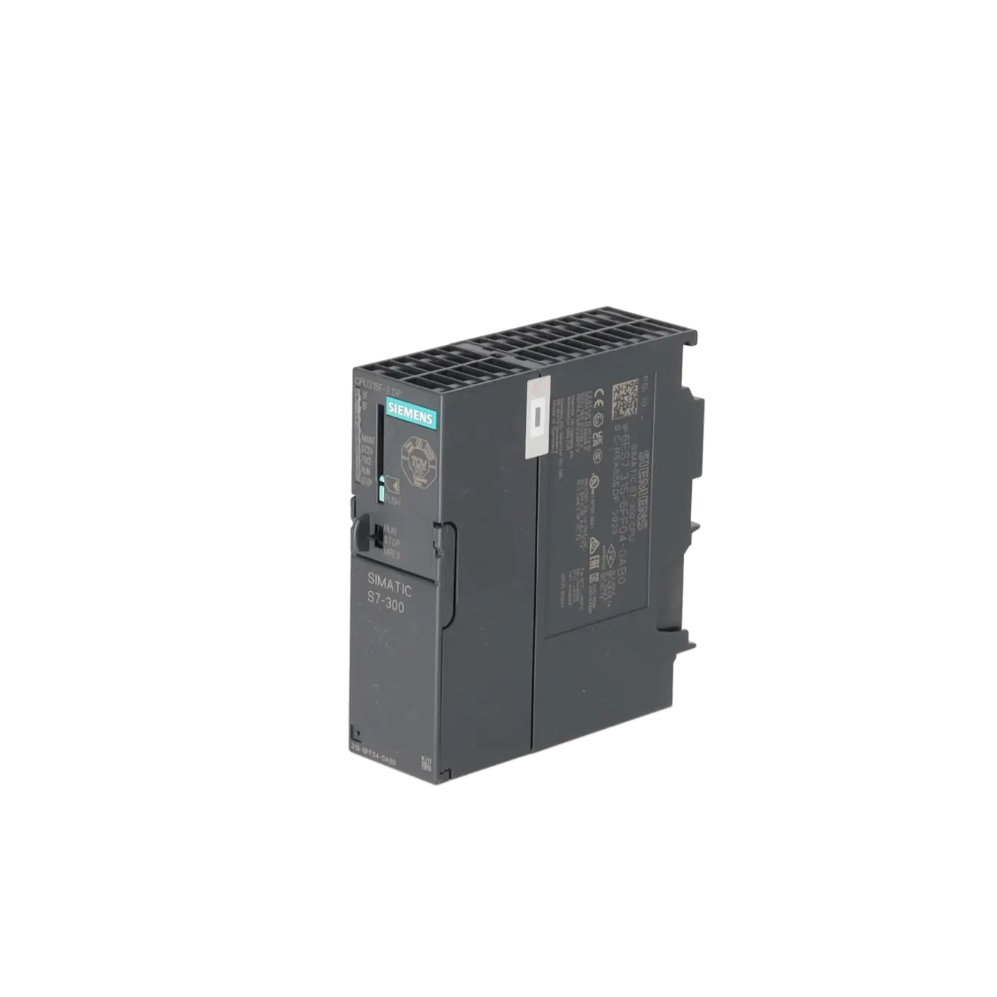
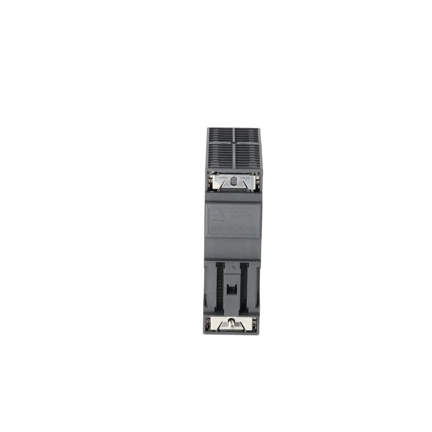
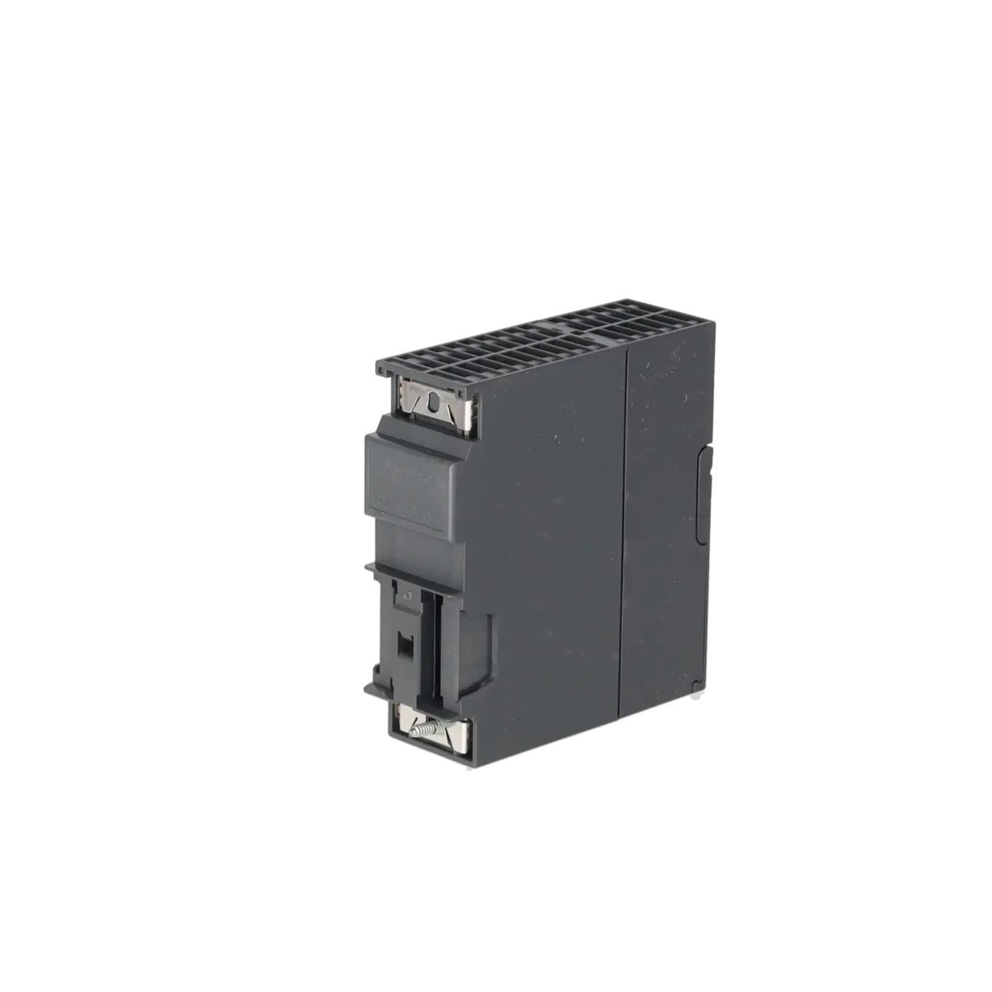
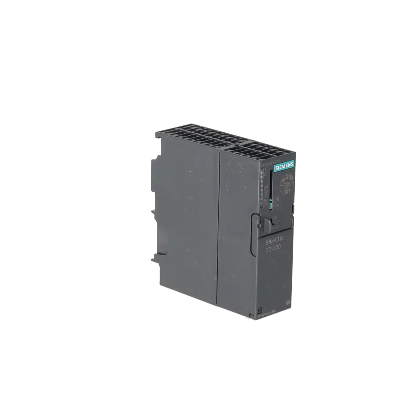
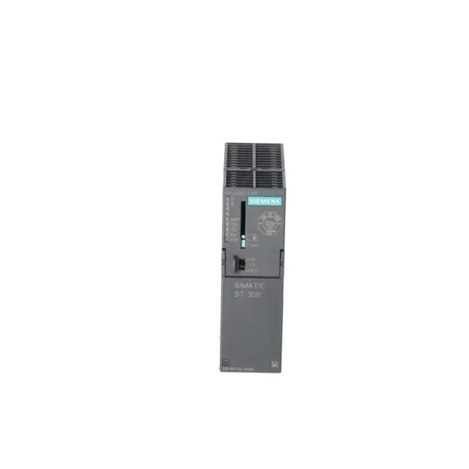
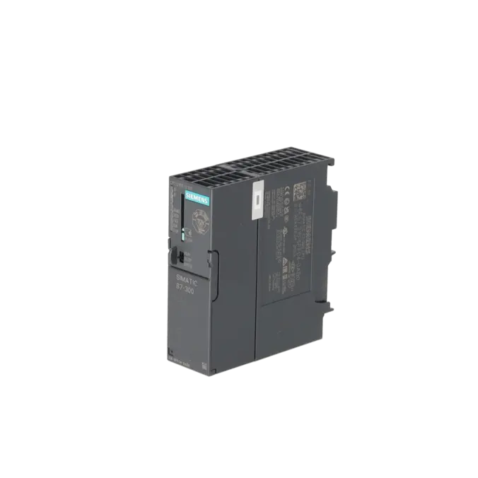
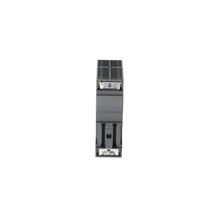
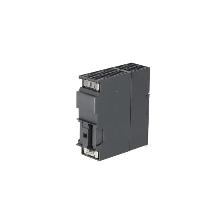
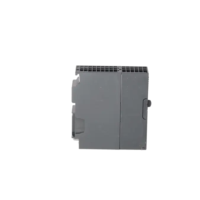
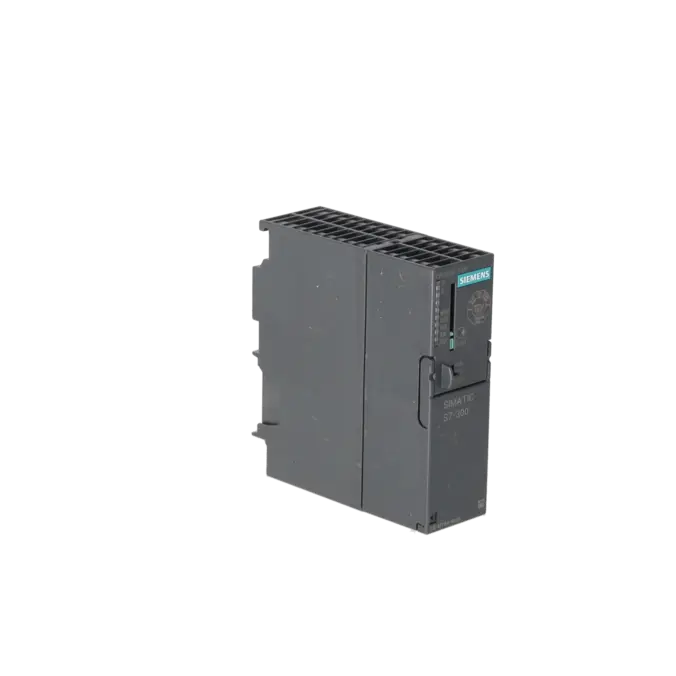
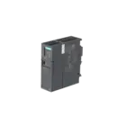
SIMATIC S7-300, CPU 315F-2DP FAIL-SAFE MODULE WITH MPI INTEGR. POWER SUPPLY 24 V DC, WORK MEMORY 384 KB, 40 MM WIDTH, 2ND INTERFACE DP MASTER/SLAVE MICRO MEMORY CARD REQUIRED
Services for SIEMENS 6ES7315-6FF04-0AB0
Repair
from 987,65 €
to 1.777,76 €
Replacement
2.759,43 €
2.069,57 €
Used
3.066,03 €
2.299,52 €
New
3.406,70 €
2.555,02 €
SIEMENS |
6ES7315-6FF04-0AB0 –
additional product information
| Delivery information | |||
|---|---|---|---|
| Export identifier | AL: N ECCN: EAR99H | ||
| Net weight | 0.344 | ||
| Quantity | 1 Stück | ||
| Packaging quantity | 1 | ||
| Additional product information | |||
|---|---|---|---|
| Product status | EOP: 2025-10-01 | ||
| EAN | 4025515077756 | ||
| UPC | 040892550320 | ||
| Static lot number | 85371091 | ||
| List indicator | ST73 | ||
| Product group | 4A89 | ||
| Country of origin | DE | ||
| Compliance with the substance restrictions according to RoHS directive | Since: 20091125 | ||
| Product classifications | Version | Classification | |
|---|---|---|---|
| eClass | 4 | 27-24-03-02 | |
| eClass | 5.1 | 27-24-22-07 | |
| eClass | 6.0 | 27-24-22-07 | |
| ETIM | 3 | / | |
| ETIM | 4 | EC000236 | |
| ETIM | 5 | EC000236 | |
What is the 6ES7315-6FF04-0AB0 and where is it used?
The 6ES7315-6FF04-0AB0 is a Siemens SIMATIC S7-300 CPU 315F-2 DP. It is a fail-safe CPU designed for applications where standard automation functions and safety functions must be integrated within the same controller. Typical application areas include machines and systems using PROFIBUS and PROFIsafe, such as manufacturing lines, conveyor systems, packaging machinery and process plants. The module operates on 24 V DC, features an MPI interface and a second PROFIBUS DP master/device interface, and requires a Micro Memory Card (MMC) for operation. For maintenance personnel, it is particularly relevant when an existing S7-300F installation must remain operational without extensive modifications.
Overview of the key technical data and what it means
The CPU provides 384 KB of work memory, integrated use of load memory via an MMC of up to 8 MB, a 24 V DC power supply, a width of 40 mm and a typical power loss of 4.5 W. In practice, the work memory determines how much user program and data can be actively processed, while the MMC permanently stores the application and is therefore essential for start-up, data backup and service activities. The CPU supports up to 2,048 bytes of inputs and outputs, up to 16,384 digital channels and 1,024 analogue channels, includes a diagnostic buffer with 500 entries, and is designed for operation at temperatures between 0 and 60 °C. For maintenance and troubleshooting, these specifications are particularly important because they directly affect compatibility, performance limits and diagnostic capabilities.
Product status, life-cycle status and obsolescence
Siemens classifies the 6ES7315-6FF04-0AB0 as a spare part. Siemens product information specifies a product discontinuation date of 01 October 2025, and EICHLER likewise lists the product status as EOP 2025-10-01. For operators, this means that although the CPU remains highly relevant for existing installations, it clearly falls within the scope of obsolescence management, spare-parts planning and lifetime extension strategies. Siemens provides an important migration reference in its migration guide, where the CPU 1513F-1 PN (6ES7513-1FL01-0AB0) is identified as the corresponding migration target. Siemens also explicitly states that this mapping is intended for guidance only. It should therefore be viewed as a migration path towards a modern safety controller rather than a direct plug-and-play replacement.
Available EICHLER services and their practical relevance
For this CPU, EICHLER offers repair, exchange, used equipment and new equipment options. Repair is particularly suitable when the installed hardware version must remain unchanged within the machine and downtime costs associated with a complete retrofit are to be avoided. According to the product information, the repair service includes technical cleaning, preventive maintenance, comprehensive functional testing and a minimum 24-month warranty. Exchange services are the preferred option when production must be restored as quickly as possible. Used equipment is often an economical choice for supporting older systems, while new equipment is especially suitable for structured spare-parts stocking strategies. In addition, an optional F-CPU test report is available, which can be particularly valuable in safety-related applications where documentation and proof of functionality are required.
| Attribute | Value |
|---|---|
| General information | |
| Product type designation | CPU 315F-2 DP |
| HW functional status | 1 |
| Firmware version | V3.3 |
| Product function | |
| ● Isochronous mode | Yes |
| Engineering with | |
| ● Programming package | STEP 7 V5.5 + SP1 or higher or STEP 7 V5.2 + SP1 or higher with HSP 218 + Distributed Safety |
| Supply voltage | |
| Rated value (DC) | 24 V |
| permissible range, lower limit (DC) | 19.2 V |
| permissible range, upper limit (DC) | 28.8 V |
| external protection for power supply lines (recommendation) | 2 A min. |
| Mains buffering | |
| ● Mains/voltage failure stored energy time | 5 ms |
| ● Repeat rate, min. | 1 s |
| Input current | |
| Current consumption (rated value) | 850 mA |
| Current consumption (in no-load operation), typ. | 150 mA |
| Inrush current, typ. | 3.5 A |
| I²t | 1 A²·s |
| Power loss | |
| Power loss, typ. | 4.5 W |
| Memory | |
| Work memory | |
| ● integrated | 384 kbyte |
| ● expandable | No |
| Load memory | |
| ● Plug-in (MMC) | Yes |
| ● Plug-in (MMC), max. | 8 Mbyte |
| ● Data management on MMC (after last programming), min. | 10 a |
| Backup | |
| ● present | Yes; Guaranteed by MMC (maintenance-free) |
| ● without battery | Yes; Program and data |
| CPU processing times | |
| for bit operations, typ. | 0.05 µs |
| for word operations, typ. | 0.09 µs |
| for fixed point arithmetic, typ. | 0.12 µs |
| for floating point arithmetic, typ. | 0.45 µs |
| CPU-blocks | |
| Number of blocks (total) | 1 024; (DBs, FCs, FBs); the maximum number of loadable blocks can be reduced by the MMC used. |
| DB | |
| ● Number, max. | 1 024; Number range: 1 to 16000 |
| ● Size, max. | 64 kbyte |
| FB | |
| ● Number, max. | 1 024; Number range: 0 to 7999 |
| ● Size, max. | 64 kbyte |
| FC | |
| ● Number, max. | 1 024; Number range: 0 to 7999 |
| ● Size, max. | 64 kbyte |
| OB | |
| ● Number, max. | see instruction list |
| ● Size, max. | 64 kbyte |
| ● Number of free cycle OBs | 1; OB 1 |
| ● Number of time alarm OBs | 1; OB 10 |
| ● Number of delay alarm OBs | 2; OB 20, 21 |
| ● Number of cyclic interrupt OBs | 4; OB 32, 33, 34, 35 |
| ● Number of process alarm OBs | 1; OB 40 |
| ● Number of DPV1 alarm OBs | 3; OB 55, 56, 57 |
| ● Number of isochronous mode OBs | 1; OB 61 |
| ● Number of startup OBs | 1; OB 100 |
| ● Number of asynchronous error OBs | 5; OB 80, 82, 85, 86, 87 |
| ● Number of synchronous error OBs | 2; OB 121, 122 |
| Nesting depth | |
| ● per priority class | 16 |
| ● additional within an error OB | 4 |
| Counters, timers and their retentivity | |
| S7 counter | |
| ● Number | 256 |
| Retentivity | |
| — adjustable | Yes |
| — preset | Z 0 to Z 7 |
| Counting range | |
| — lower limit | 0 |
| — upper limit | 999 |
| IEC counter | |
| ● present | Yes |
| ● Type | SFB |
| ● Number | Unlimited (limited only by RAM capacity) |
| S7 times | |
| ● Number | 256 |
| Retentivity | |
| — adjustable | Yes |
| — preset | No retentivity |
| Time range | |
| — lower limit | 10 ms |
| — upper limit | 9 990 s |
| IEC timer | |
| ● present | Yes |
| ● Type | SFB |
| ● Number | Unlimited (limited only by RAM capacity) |
| Data areas and their retentivity | |
| Retentive data area (incl. timers, counters, flags), max. | 128 kbyte |
| Flag | |
| ● Size, max. | 2 048 byte |
| ● Retentivity available | Yes; MB 0 to MB 2 047 |
| ● Retentivity preset | MB 0 to MB 15 |
| ● Number of clock memories | 8; 1 memory byte |
| Data blocks | |
| ● Retentivity adjustable | Yes; via non-retain property on DB |
| ● Retentivity preset | Yes |
| Local data | |
| ● per priority class, max. | 32 kbyte; Max. 2 KB per block |
| Address area | |
| I/O address area | |
| ● Inputs | 2 048 byte |
| ● Outputs | 2 048 byte |
| of which distributed | |
| — Inputs | 2 048 byte |
| — Outputs | 2 048 byte |
| Process image | |
| ● Inputs | 2 048 byte |
| ● Outputs | 2 048 byte |
| ● Inputs, adjustable | 2 048 byte |
| ● Outputs, adjustable | 2 048 byte |
| ● Inputs, default | 384 byte |
| ● Outputs, default | 384 byte |
| Subprocess images | |
| ● Number of subprocess images, max. | 1 |
| Digital channels | |
| ● Inputs | 16 384 |
| — of which central | 1 024 |
| ● Outputs | 16 384 |
| — of which central | 1 024 |
| Analog channels | |
| ● Inputs | 1 024 |
| — of which central | 256 |
| ● Outputs | 1 024 |
| — of which central | 256 |
| Hardware configuration | |
| Number of expansion units, max. | 3 |
| Number of DP masters | |
| ● integrated | 1 |
| ● via CP | 4 |
| Number of operable FMs and CPs (recommended) | |
| ● FM | 8 |
| ● CP, PtP | 8 |
| ● CP, LAN | 10 |
| Rack | |
| ● Racks, max. | 4 |
| ● Modules per rack, max. | 8 |
| Time of day | |
| Clock | |
| ● Hardware clock (real-time) | Yes |
| ● retentive and synchronizable | Yes |
| ● Backup time | 6 wk; At 40 °C ambient temperature |
| ● Deviation per day, max. | 10 s; Typ.: 2 s |
| ● Behavior of the clock following POWER-ON | Clock continues running after POWER OFF |
| ● Behavior of the clock following expiry of backup period | the clock continues at the time of day it had when power was switched off |
| Operating hours counter | |
| ● Number | 1 |
| ● Number/Number range | 0 |
| ● Range of values | 0 to 2^31 hours (when using SFC 101) |
| ● Granularity | 1 h |
| ● retentive | Yes; Must be restarted at each restart |
| Clock synchronization | |
| ● supported | Yes |
| ● to MPI, master | Yes |
| ● on MPI, device | Yes |
| ● to DP, master | Yes; With DP slave only slave clock |
| ● on DP, device | Yes |
| ● in AS, master | Yes |
| ● in AS, device | No |
| Digital inputs | |
| Number of digital inputs | 0 |
| Digital outputs | |
| Number of digital outputs | 0 |
| Analog inputs | |
| Number of analog inputs | 0 |
| Interfaces | |
| Number of PROFINET interfaces | 0 |
| Number of RS 485 interfaces | 2 |
| Number of RS 422 interfaces | 0 |
| 1. Interface | |
| Interface type | Integrated RS 485 interface |
| Isolated | No |
| Interface types | |
| ● RS 485 | Yes |
| ● Output current of the interface, max. | 200 mA |
| Protocols | |
| ● MPI | Yes |
| ● PROFIBUS DP master | No |
| ● PROFIBUS DP device | No |
| ● Point-to-point connection | No |
| MPI | |
| ● Transmission rate, max. | 187.5 kbit/s |
| Services | |
| — PG/OP communication | Yes |
| — Routing | Yes |
| — Global data communication | Yes |
| — S7 basic communication | Yes |
| — S7 communication | Yes; Only server, configured on one side |
| — S7 communication, as client | No |
| — S7 communication, as server | Yes |
| 2. Interface | |
| Interface type | Integrated RS 485 interface |
| Isolated | Yes |
| Interface types | |
| ● RS 485 | Yes |
| ● Output current of the interface, max. | 200 mA |
| Protocols | |
| ● MPI | No |
| ● PROFIBUS DP master | Yes |
| ● PROFIBUS DP device | Yes |
| ● Point-to-point connection | No |
| PROFIBUS DP master | |
| ● Transmission rate, max. | 12 Mbit/s |
| ● max. number of DP devices | 124; Per station |
| Services | |
| — PG/OP communication | Yes |
| — Routing | Yes |
| — Global data communication | No |
| — S7 basic communication | Yes; I blocks only |
| — S7 communication | Yes; Only server, configured on one side |
| — S7 communication, as client | No |
| — S7 communication, as server | Yes |
| — Equidistance | Yes |
| — Isochronous mode | Yes; OB 61 |
| — SYNC/FREEZE | Yes |
| — activation/deactivation of DP devices | Yes |
| — max. number of DP devices that can be activated/deactivated at the same time | 8 |
| — DPV1 | Yes |
| Address area | |
| — Inputs, max. | 2 048 byte |
| — Outputs, max. | 2 048 byte |
| User data per DP device | |
| — Inputs, max. | 244 byte |
| — Outputs, max. | 244 byte |
| PROFIBUS DP device | |
| ● GSD file | The latest GSD file is available at: http://www.siemens.com/profibus-gsd |
| ● Transmission rate, max. | 12 Mbit/s |
| ● automatic baud rate search | Yes; only with passive interface |
| ● Address area, max. | 32 |
| ● User data per address area, max. | 32 byte |
| Services | |
| — PG/OP communication | Yes |
| — Routing | Yes; Only with active interface |
| — Global data communication | No |
| — S7 basic communication | No |
| — S7 communication | Yes; Only server, configured on one side |
| — S7 communication, as client | No |
| — S7 communication, as server | Yes |
| — Direct data exchange (slave-to-slave communication) | Yes |
| — DPV1 | No |
| Transfer memory | |
| — Inputs | 244 byte |
| — Outputs | 244 byte |
| Protocols | |
| PROFIsafe | Yes |
| Communication functions | |
| PG/OP communication | Yes |
| Data record routing | Yes |
| Global data communication | |
| ● supported | Yes |
| ● Number of GD loops, max. | 8 |
| ● Number of GD packets, max. | 8 |
| ● Number of GD packets, transmitter, max. | 8 |
| ● Number of GD packets, receiver, max. | 8 |
| ● Size of GD packets, max. | 22 byte |
| ● Size of GD packet (of which consistent), max. | 22 byte |
| S7 basic communication | |
| ● supported | Yes |
| ● User data per job, max. | 76 byte |
| ● User data per job (of which consistent), max. | 76 byte; 76 bytes (with X_SEND or X_RCV); 64 bytes (with X_PUT or X_GET as server) |
| S7 communication | |
| ● supported | Yes |
| ● as server | Yes |
| ● as client | Yes; Via CP and loadable FB |
| ● User data per job, max. | 180 byte; With PUT/GET |
| ● User data per job (of which consistent), max. | 240 byte; as server |
| S5 compatible communication | |
| ● supported | Yes; via CP and loadable FC |
| Number of connections | |
| ● overall | 16 |
| ● usable for PG communication | 15 |
| — reserved for PG communication | 1 |
| — adjustable for PG communication, min. | 1 |
| — adjustable for PG communication, max. | 15 |
| ● usable for OP communication | 15 |
| — reserved for OP communication | 1 |
| — adjustable for OP communication, min. | 1 |
| — adjustable for OP communication, max. | 15 |
| ● usable for S7 basic communication | 12 |
| — reserved for S7 basic communication | 0 |
| — adjustable for S7 basic communication, min. | 0 |
| — adjustable for S7 basic communication, max. | 12 |
| S7 message functions | |
| Number of login stations for message functions, max. | 16; Depending on the configured connections for PG/OP and S7 basic communication |
| Process diagnostic messages | Yes |
| simultaneously active Alarm_S blocks, max. | 300 |
| Test commissioning functions | |
| Status block | Yes; Up to 2 simultaneously |
| Single step | Yes |
| Number of breakpoints | 4 |
| Status/control | |
| ● Status/control variable | Yes |
| ● Variables | Inputs, outputs, memory bits, DB, times, counters |
| ● Number of variables, max. | 30 |
| — of which status variables, max. | 30 |
| — of which control variables, max. | 14 |
| Forcing | |
| ● Forcing | Yes |
| ● Forcing, variables | Inputs, outputs |
| ● Number of variables, max. | 10 |
| Diagnostic buffer | |
| ● present | Yes |
| ● Number of entries, max. | 500 |
| — adjustable | No |
| — of which powerfail-proof | 100; Only the last 100 entries are retained |
| ● Number of entries readable in RUN, max. | |
| — adjustable | Yes; From 10 to 499 |
| — preset | 10 |
| Service data | |
| ● can be read out | Yes |
| Ambient conditions | |
| Ambient temperature during operation | |
| ● min. | 0 °C |
| ● max. | 60 °C |
| Configuration | |
| Configuration software | |
| ● STEP 7 | Yes; V5.2 SP1 or higher with HW update |
| Programming | |
| ● Command set | see instruction list |
| ● Nesting levels | 8 |
| ● System functions (SFC) | see instruction list |
| ● System function blocks (SFB) | see instruction list |
| Programming language | |
| — LAD | Yes |
| — FBD | Yes |
| — STL | Yes |
| — SCL | Yes |
| — CFC | Yes |
| — GRAPH | Yes |
| — HiGraph® | Yes |
| Know-how protection | |
| ● User program protection/password protection | Yes |
| ● Block encryption | Yes; With S7 block Privacy |
| Dimensions | |
| Width | 40 mm |
| Height | 125 mm |
| Depth | 130 mm |
| Weights | |
| Weight, approx. | 290 g |
| Fault description | Possible solution |
|---|---|
| Why are the SF and BF LEDs illuminated on the CPU 315F-2 DP? | In many cases, the cause is a PROFIBUS issue, such as an incorrect or duplicate slave address, a missing terminating resistor, a broken bus cable or a hardware configuration that does not match the actual installation. First check the bus connectors, the termination resistors at both ends of the segment and whether only the physically connected devices have been configured in the project. Then open the CPU's diagnostic buffer and compare the reported station with the hardware configuration. If the BF/SF condition occurs intermittently, the actual network topology should also be compared with the configured bus participants. |
| Why does the diagnostic buffer contain the message 16#4546 STOP caused by CPU memory management? | Siemens identifies an MMC access fault as a typical cause of this message. The Micro Memory Card (MMC) is mandatory for operation of this CPU. Therefore, check whether the correct MMC is installed and whether the contacts and card slot are in good condition. Verify that the card remains readable. Afterwards, switch off the power supply, reinsert the MMC correctly and, if necessary, reload the project. If the fault reappears, a defective or inconsistent MMC is highly likely and the card should be replaced. |
| Why can a safety-related program not be downloaded to the CPU 315F-2 DP? | Typical causes include an incompatible engineering software version, inconsistent safety data stored on the MMC or a modified F-signature following project changes. Siemens notes that certain firmware and safety-related functions require compatible versions of STEP 7 and Distributed Safety, depending on the configured protection level and the existing safety program. In practice, the following approach is usually effective: compare the hardware configuration and the safety project completely, compile the standard and safety sections consistently, download the system data again and, if outdated data is suspected, remove the existing safety-related data from the MMC before transferring it again. |
| Why does the S7-300 remain in STOP after adding a CP or FM module? | Siemens describes this behaviour for S7-300 CPUs following the installation of additional CP or FM modules. In practice, the hardware configuration, occupied address ranges, compatible firmware versions and the actually installed modules should all be checked. Afterwards, save, compile and download the entire station configuration again. Following hardware modifications, a clean restart of the controller is also advisable, as newly installed modules and updated system data often become fully operational only after a restart. Particularly in older installations, it is essential to ensure consistency between the installed hardware, the project version and the MMC currently in use. |
Is the 6ES7315-6FF04-0AB0 a PROFINET CPU?
No. The 6ES7315-6FF04-0AB0 is a CPU 315F-2 DP equipped with an MPI interface and a second PROFIBUS DP master/device interface. It does not provide an integrated PROFINET interface. Anyone requiring PROFINET connectivity must therefore pay close attention to the specific PN/DP variants. For procurement and maintenance teams, this distinction is important because it directly affects the network architecture, diagnostic methods, system topology and the feasibility of replacing components in existing installations. A seemingly similar S7-300 CPU is therefore not automatically compatible if the communication interfaces differ.
Which engineering software is required for this F-CPU?
Siemens specifies STEP 7 V5.5 + SP1 or later, alternatively STEP 7 V5.2 + SP1 together with HSP 218 and Distributed Safety. For existing installations, this is a critical consideration because many service interventions fail not because of hardware issues but because the engineering environment is incompatible. Before replacing the CPU or downloading a project, it is therefore advisable to verify which software version was originally used to create the application and whether the available engineering station fully supports both the CPU and its safety functions.
Why is the Micro Memory Card so important for this CPU?
The CPU does not contain integrated load memory that permanently stores the user program without an external memory card. Siemens explicitly states that the Micro Memory Card (MMC) is mandatory, and the technical documentation identifies the plug-in MMC as the load memory medium. For operators, this means that the CPU cannot enter normal operation without a suitable and functional MMC. Whenever a replacement CPU is installed, verification of the MMC should form part of the standard procedure, including confirmation that the card contains the correct project version and consistent system data.
Is the module still active or already discontinued?
The CPU is still listed by Siemens as a spare part, but a product discontinuation date of 01 October 2025 has been announced. EICHLER likewise identifies the product status as EOP 2025-10-01. For procurement and maintenance departments, this means that the CPU remains important for supporting existing systems but should no longer be regarded as a long-term strategic platform. Anyone responsible for maintaining extended service life should therefore plan spare-parts stock, repair capability and a future migration strategy well in advance rather than waiting for a failure to occur.
Is there a Siemens successor or only a migration path?
In its migration guide, Siemens associates the CPU 1513F-1 PN (6ES7513-1FL01-0AB0) with the 6ES7315-6FF04-0AB0. Siemens also explicitly states that the mapping table is intended only as a guide. In practical terms, this means that there is a clearly defined migration path towards the S7-1500F platform, but no direct plug-and-play replacement. Before undertaking such a migration, the communication structure, safety application, I/O architecture, diagnostic concept and documentation should all be reviewed together.
Should I repair, exchange or purchase a replacement if the CPU fails?
The best approach depends primarily on the required recovery time, the criticality of the installation and the availability of project resources. Repair is often the preferred option when the existing hardware version must be retained and the system cannot be redesigned. An exchange unit is usually more suitable when production must be restored as quickly as possible. Used equipment can be a cost-effective solution when an older S7-300F installation needs to remain operational for several more years. New equipment is often selected when building a qualified spare-parts stock for critical machinery. For this CPU, EICHLER supports all four options and additionally offers an optional F-CPU test report, which can be particularly valuable in safety-related applications requiring documented proof of functionality.