SIEMENS 6ES7314-6EH04-0AB0
-
SIEMENS | PLC Controls | Central Processing Units
- EICHLER-art.no.: K0252210
- EAN: 4025515079125
- UPC: 040892631845
Product description
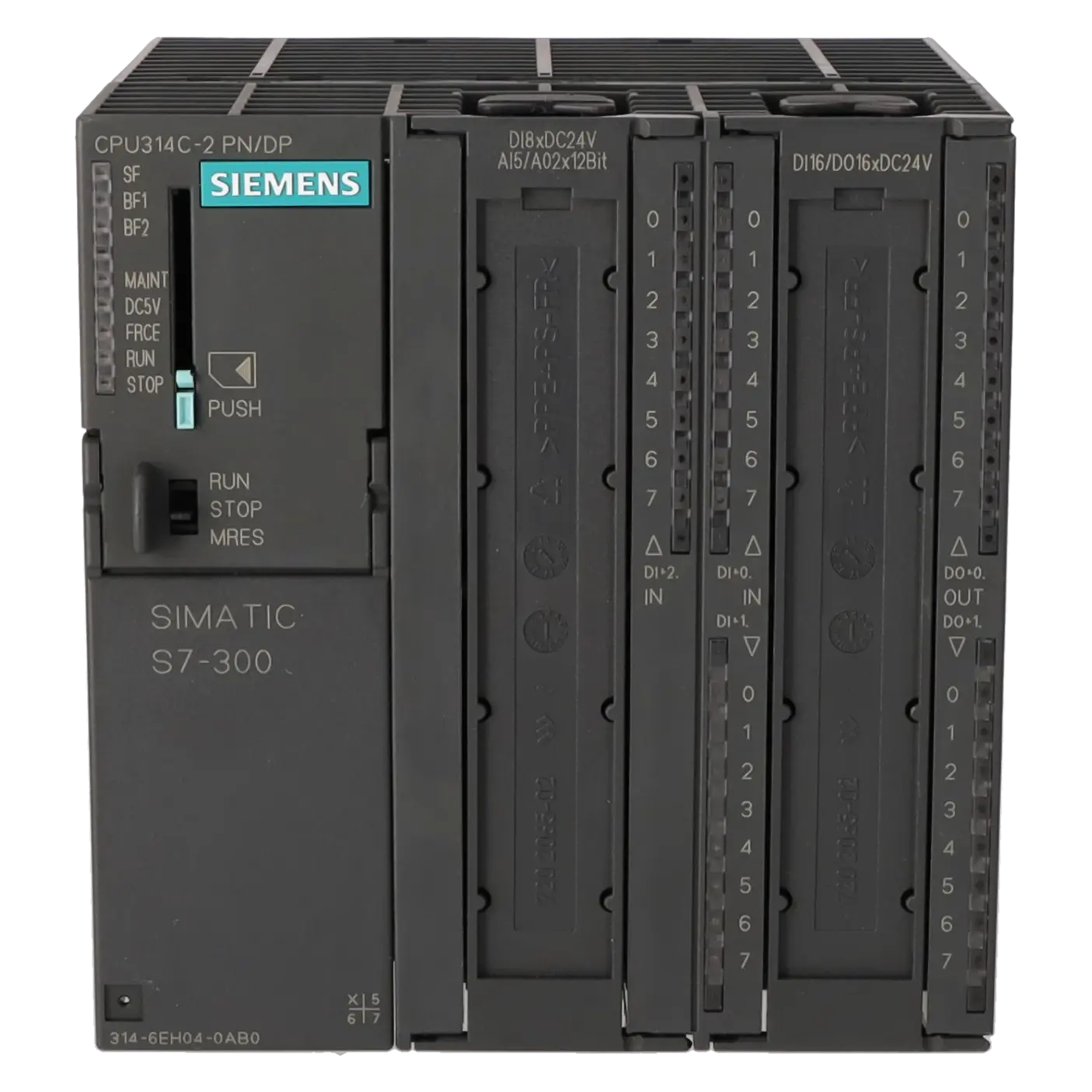
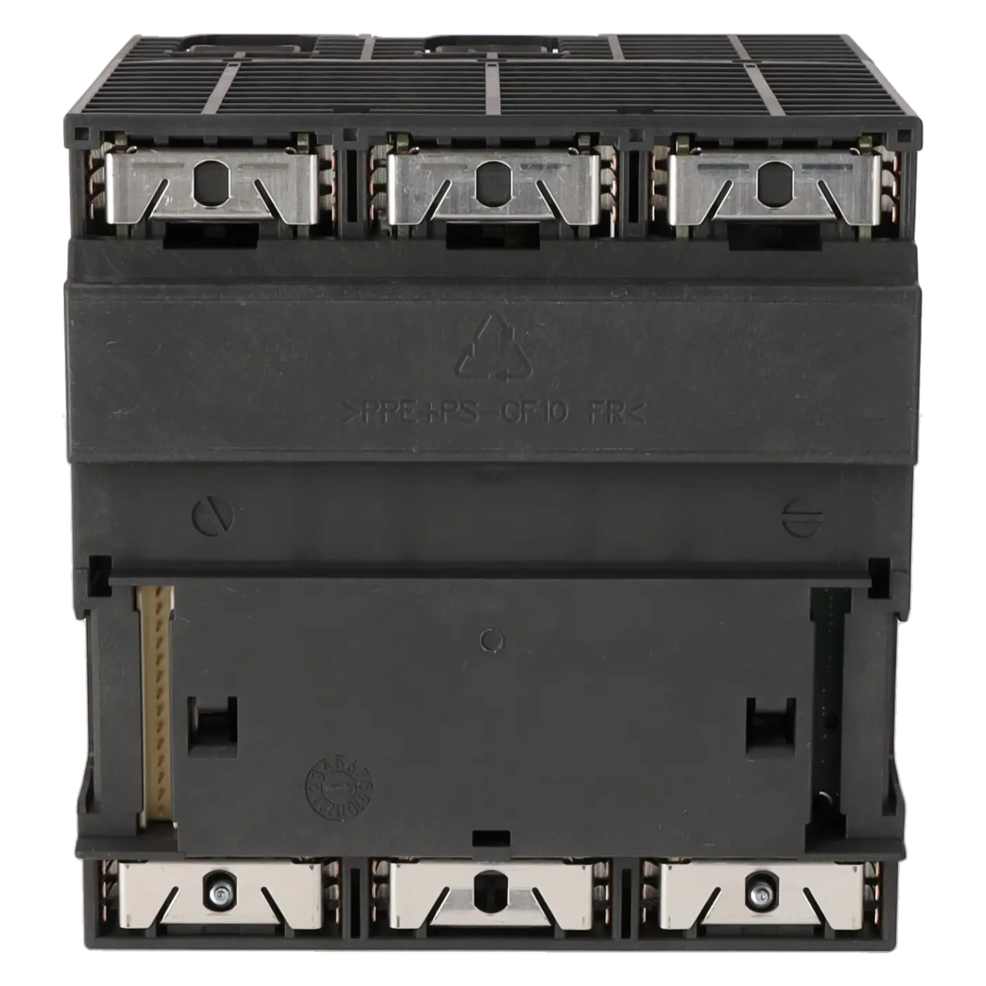
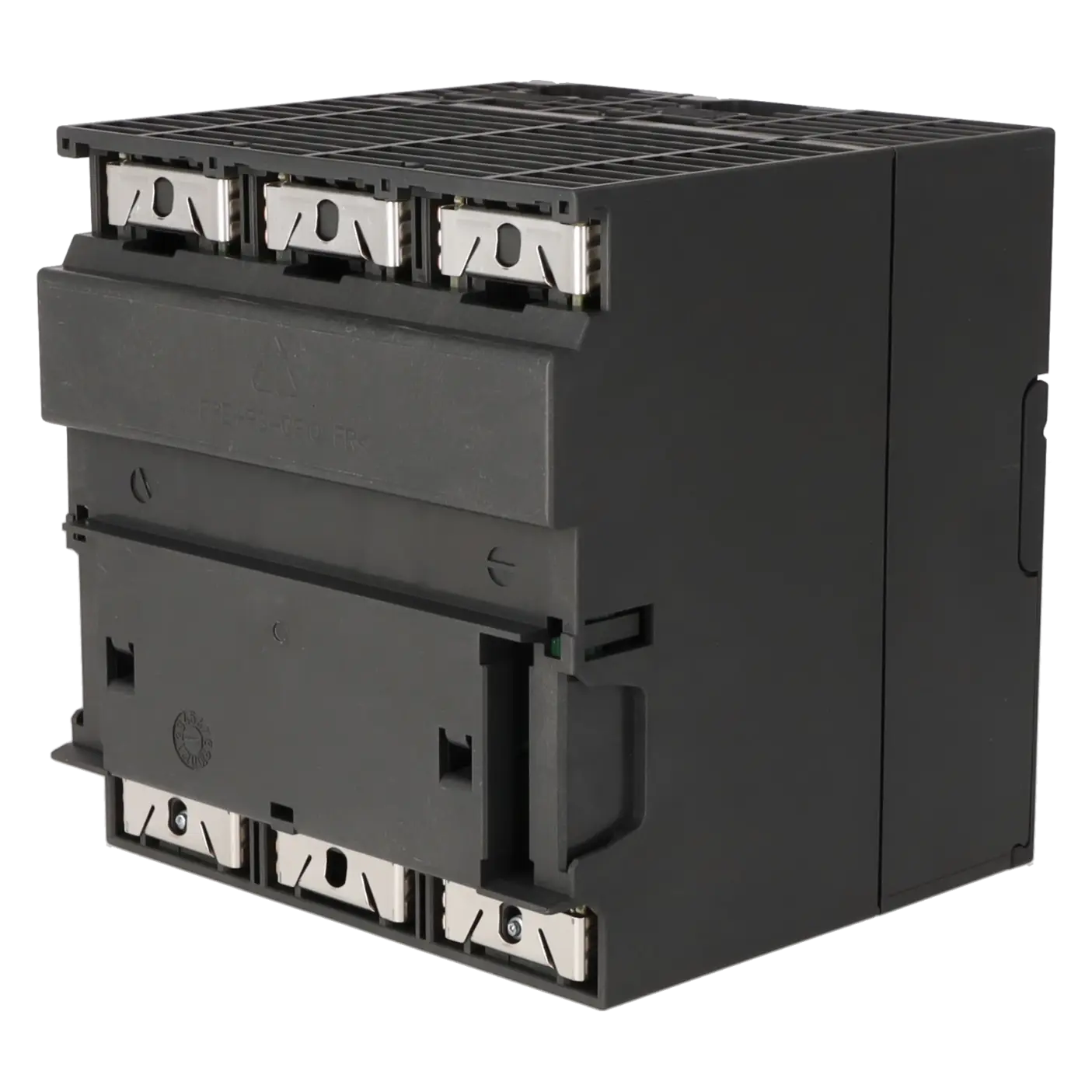
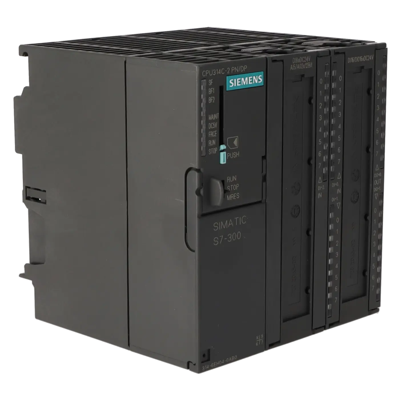
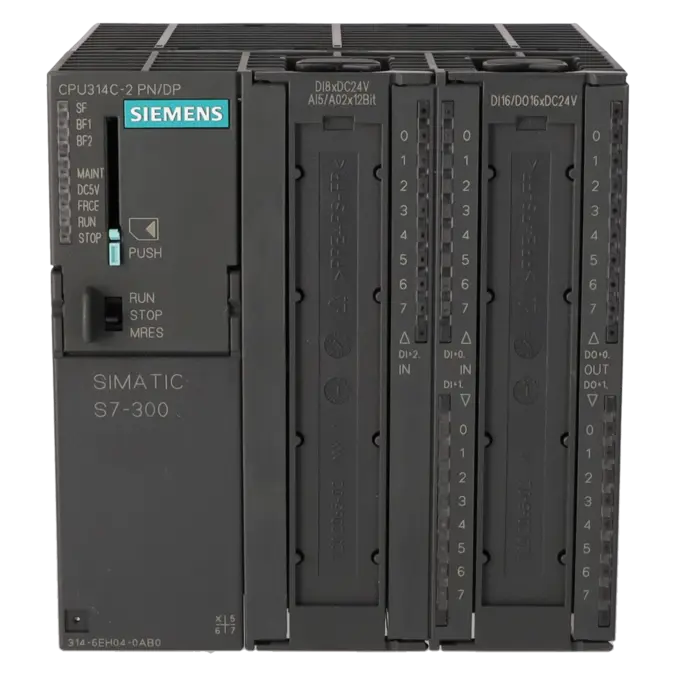
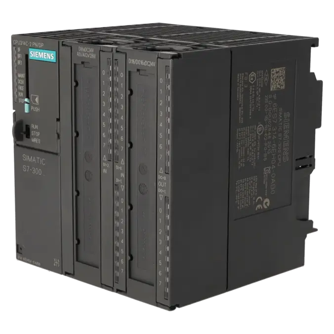
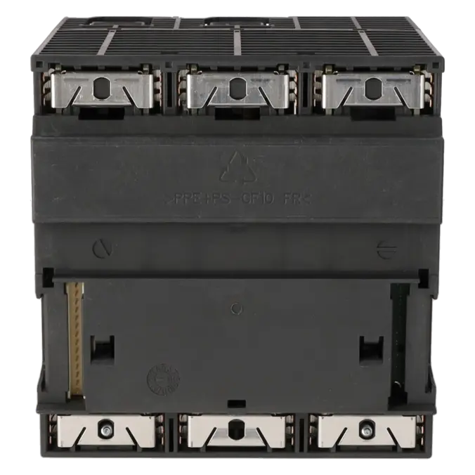
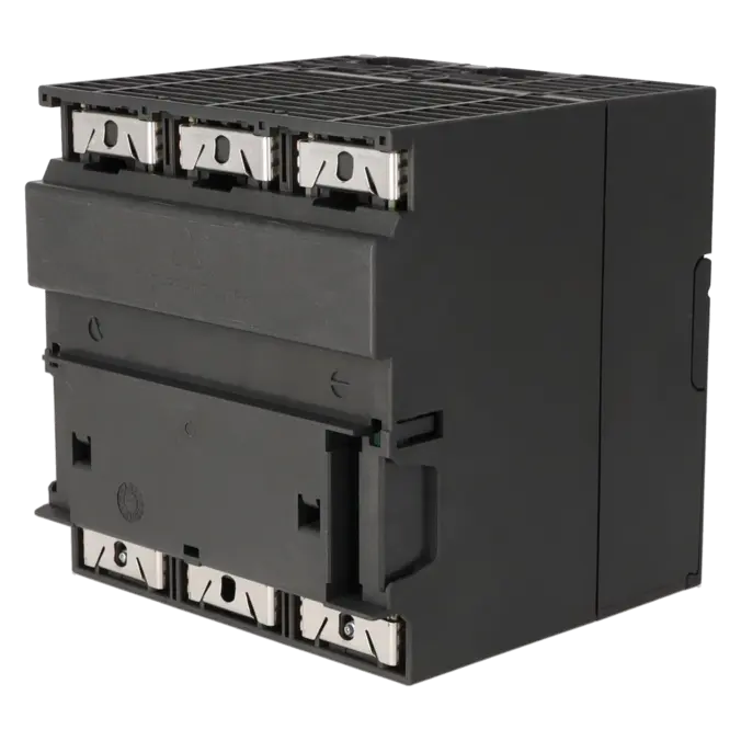
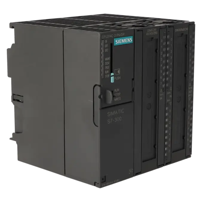
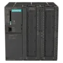
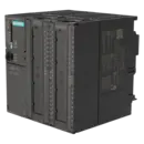
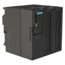
SIMATIC S7-300, CPU 314C-2PN/DP COMPACT CPU WITH 192 KB WORK MEMORY, 24 DI/16 DO, 4 AI, 2 AO, 1 PT100, 4 HIGH-SPEED COUNTERS (60 KHZ), 1ST INTERFACE MPI/DP 12 MBIT/S, 2ND INTERFACE ETHERNET PROFINET, WITH 2-PORT SWITCH, INTEGR. POWER SUPPLY 24 V DC, FRONT
Services for SIEMENS 6ES7314-6EH04-0AB0
Repair
from 1.346,70 €
to 2.424,06 €
Replacement
1.826,35 €
1.369,76 €
Used
2.561,53 €
1.921,15 €
New
3.358,30 €
2.518,72 €
SIEMENS |
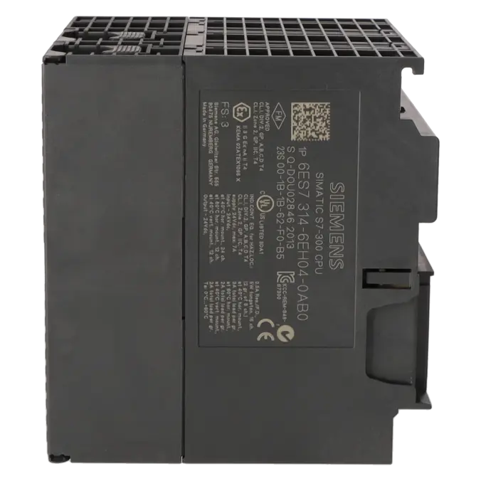
6ES7314-6EH04-0AB0 –
additional product information
| Delivery information | |||
|---|---|---|---|
| Export identifier | AL: N ECCN: EAR99H | ||
| Net weight | 0.785 | ||
| Quantity | 1 Stück | ||
| Packaging quantity | 1 | ||
| Additional product information | |||
|---|---|---|---|
| Product status | EOP: 2025-10-01 | ||
| EAN | 4025515079125 | ||
| UPC | 040892631845 | ||
| Static lot number | 85371091 | ||
| List indicator | ST73 | ||
| Product group | 4256 | ||
| Country of origin | DE | ||
| Compliance with the substance restrictions according to RoHS directive | Since: 20110913 | ||
| Product classifications | Version | Classification | |
|---|---|---|---|
| eClass | 4 | 27-24-03-02 | |
| eClass | 5.1 | 27-24-22-07 | |
| eClass | 6.0 | 27-24-22-07 | |
| ETIM | 3 | / | |
| ETIM | 4 | EC000236 | |
| ETIM | 5 | EC000236 | |
What is the 6ES7314-6EH04-0AB0 and where is it used?
The 6ES7314-6EH04-0AB0 is a SIMATIC S7-300 CPU 314C-2 PN/DP from Siemens. It is a compact CPU featuring an integrated 24 V DC power supply, 24 digital inputs, 16 digital outputs, 4 analogue inputs, 2 analogue outputs, 1 Pt100 input, 4 high-speed counters up to 60 kHz, an MPI/DP interface, and a PROFINET interface with an integrated 2-port switch. This makes the module particularly suitable for compact machines and existing installations where control functionality, local I/O and network connectivity need to be combined within a single CPU. Typical applications include conveyor systems, packaging machinery, special-purpose machines, handling equipment and retrofit projects in existing S7-300 environments.
Overview of the key technical specifications and what they mean
The CPU operates on 24 V DC and, according to Siemens, supports a voltage range of 19.2 to 28.8 V DC. Its 192 KB working memory is sufficient for many traditional machine and automation programs. An important practical consideration is that the load memory is stored on a plug-in Micro Memory Card (MMC), which is required for operation and program storage. The integrated I/O reduces the amount of additional hardware required in the control cabinet, while the 4 high-speed counters are well suited for encoder signals, pulse counting and positioning tasks. On the communications side, the CPU provides PROFINET with an integrated 2-port switch, a web server, support for up to 5 HTTP clients, NTP time synchronisation, and the ability to replace devices without removable storage media. Siemens specifies STEP 7 V5.5 with HSP 191 as the required engineering environment.
Product status, life-cycle status and obsolescence
For the 6ES7314-6EH04-0AB0, the lifecycle focus has clearly shifted towards supporting existing installations. Siemens lists the product as a spare part and identifies its lifecycle status as Product Cancellation. In addition, the EICHLER product page specifies EOP (End of Product): 01 October 2025. Siemens has also assigned the PM410 phase-out milestone to the SIMATIC S7-300 / ET 200M product family, effective 01 October 2025. An explicitly designated 1:1 successor for this specific compact CPU is not clearly identified in the available Siemens product documentation. For modernisation and migration projects, Siemens instead recommends migration from S7-300 to S7-1500 systems; in official comparison scenarios, the S7-1200 CPU 1217C is also referenced as a functionally related migration option.
Available EICHLER services and when they are relevant in practice
For operators of existing systems, repair is often the fastest solution when the existing project, wiring and spare-parts strategy need to remain unchanged. EICHLER offers repair services for this CPU with a typical turnaround time of 2–5 days, including technical cleaning, preventive maintenance, comprehensive functional testing and a minimum 24-month warranty. If production downtime must be minimised immediately, an exchange unit is often the lower-risk option; EICHLER indicates a lead time of 1–3 days for exchange units. In addition, used and new units are available, along with an optional test report. For purchasing and production departments, this combination is valuable because it reduces downtime, keeps the choice between repair, exchange and replacement open, and helps maintain supply security even after the product has entered its obsolescence phase.
| Attribute | Value |
|---|---|
| General information | |
| Product type designation | CPU 314C-2 PN/DP |
| HW functional status | 1 |
| Firmware version | V3.3 |
| Product function | |
| ● Isochronous mode | Yes; For PROFINET only |
| Engineering with | |
| ● Programming package | STEP 7 V5.5 or higher with HSP 191 |
| Supply voltage | |
| Rated value (DC) | 24 V |
| permissible range, lower limit (DC) | 19.2 V |
| permissible range, upper limit (DC) | 28.8 V |
| external protection for power supply lines (recommendation) | Miniature circuit breaker, type C; min. 2 A; miniature circuit breaker type B, min. 4 A |
| Mains buffering | |
| ● Mains/voltage failure stored energy time | 5 ms |
| ● Repeat rate, min. | 1 s |
| Load voltage L+ | |
| Digital inputs | |
| — Rated value (DC) | 24 V |
| — Reverse polarity protection | Yes |
| Digital outputs | |
| — Rated value (DC) | 24 V |
| — Reverse polarity protection | No |
| Input current | |
| Current consumption (rated value) | 850 mA |
| Current consumption (in no-load operation), typ. | 190 mA |
| Inrush current, typ. | 5 A |
| I²t | 0.7 A²·s |
| Digital inputs | |
| ● from load voltage L+ (without load), max. | 80 mA |
| Digital outputs | |
| ● from load voltage L+, max. | 50 mA |
| Power loss | |
| Power loss, typ. | 14 W |
| Memory | |
| Work memory | |
| ● integrated | 192 kbyte |
| ● expandable | No |
| Load memory | |
| ● Plug-in (MMC) | Yes |
| ● Plug-in (MMC), max. | 8 Mbyte |
| ● Data management on MMC (after last programming), min. | 10 a |
| Backup | |
| ● present | Yes; Guaranteed by MMC (maintenance-free) |
| ● without battery | Yes; Program and data |
| CPU processing times | |
| for bit operations, typ. | 0.06 µs |
| for word operations, typ. | 0.12 µs |
| for fixed point arithmetic, typ. | 0.16 µs |
| for floating point arithmetic, typ. | 0.59 µs |
| CPU-blocks | |
| Number of blocks (total) | 1 024; (DBs, FCs, FBs); the maximum number of loadable blocks can be reduced by the MMC used. |
| DB | |
| ● Number, max. | 1 024; Number range: 1 to 16000 |
| ● Size, max. | 64 kbyte |
| FB | |
| ● Number, max. | 1 024; Number range: 0 to 7999 |
| ● Size, max. | 64 kbyte |
| FC | |
| ● Number, max. | 1 024; Number range: 0 to 7999 |
| ● Size, max. | 64 kbyte |
| OB | |
| ● Number, max. | see instruction list |
| ● Size, max. | 64 kbyte |
| ● Number of free cycle OBs | 1; OB 1 |
| ● Number of time alarm OBs | 1; OB 10 |
| ● Number of delay alarm OBs | 2; OB 20, 21 |
| ● Number of cyclic interrupt OBs | 4; OB 32, 33, 34, 35 |
| ● Number of process alarm OBs | 1; OB 40 |
| ● Number of DPV1 alarm OBs | 3; OB 55, 56, 57 |
| ● Number of isochronous mode OBs | 1; OB 61; only for PROFINET |
| ● Number of startup OBs | 1; OB 100 |
| ● Number of asynchronous error OBs | 6; OB 80, 82, 83, 85, 86, 87 (OB83 only for PROFINET IO) |
| ● Number of synchronous error OBs | 2; OB 121, 122 |
| Nesting depth | |
| ● per priority class | 16 |
| ● additional within an error OB | 4 |
| Counters, timers and their retentivity | |
| S7 counter | |
| ● Number | 256 |
| Retentivity | |
| — adjustable | Yes |
| — preset | Z 0 to Z 7 |
| Counting range | |
| — adjustable | Yes |
| — lower limit | 0 |
| — upper limit | 999 |
| IEC counter | |
| ● present | Yes |
| ● Type | SFB |
| ● Number | Unlimited (limited only by RAM capacity) |
| S7 times | |
| ● Number | 256 |
| Retentivity | |
| — adjustable | Yes |
| — preset | No retentivity |
| Time range | |
| — lower limit | 10 ms |
| — upper limit | 9 990 s |
| IEC timer | |
| ● present | Yes |
| ● Type | SFB |
| ● Number | Unlimited (limited only by RAM capacity) |
| Data areas and their retentivity | |
| Retentive data area (incl. timers, counters, flags), max. | 64 kbyte |
| Flag | |
| ● Size, max. | 256 byte |
| ● Retentivity available | Yes; MB 0 to MB 255 |
| ● Retentivity preset | MB 0 to MB 15 |
| ● Number of clock memories | 8; 1 memory byte |
| Data blocks | |
| ● Retentivity adjustable | Yes; via non-retain property on DB |
| ● Retentivity preset | Yes |
| Local data | |
| ● per priority class, max. | 32 kbyte; Max. 2048 bytes per block |
| Address area | |
| I/O address area | |
| ● Inputs | 2 048 byte |
| ● Outputs | 2 048 byte |
| of which distributed | |
| — Inputs | 2 003 byte |
| — Outputs | 2 010 byte |
| Process image | |
| ● Inputs | 2 048 byte |
| ● Outputs | 2 048 byte |
| ● Inputs, adjustable | 2 048 byte |
| ● Outputs, adjustable | 2 048 byte |
| ● Inputs, default | 256 byte |
| ● Outputs, default | 256 byte |
| Subprocess images | |
| ● Number of subprocess images, max. | 1; With PROFINET IO, the length of the user data is limited to 1600 bytes |
| Digital channels | |
| ● Inputs | 16 048 |
| — of which central | 1 016 |
| ● Outputs | 16 096 |
| — of which central | 1 008 |
| Analog channels | |
| ● Inputs | 1 006 |
| — of which central | 253 |
| ● Outputs | 1 007 |
| — of which central | 250 |
| Hardware configuration | |
| Number of expansion units, max. | 3 |
| Number of DP masters | |
| ● integrated | 1 |
| ● via CP | 4 |
| Number of operable FMs and CPs (recommended) | |
| ● FM | 8 |
| ● CP, PtP | 8 |
| ● CP, LAN | 10 |
| Rack | |
| ● Racks, max. | 4 |
| ● Modules per rack, max. | 8; In rack 3 max. 7 |
| Time of day | |
| Clock | |
| ● Hardware clock (real-time) | Yes |
| ● retentive and synchronizable | Yes |
| ● Backup time | 6 wk; At 40 °C ambient temperature |
| ● Deviation per day, max. | 10 s; Typ.: 2 s |
| ● Behavior of the clock following POWER-ON | Clock continues running after POWER OFF |
| ● Behavior of the clock following expiry of backup period | the clock continues at the time of day it had when power was switched off |
| Operating hours counter | |
| ● Number | 1 |
| ● Number/Number range | 0 |
| ● Range of values | 0 to 2^31 hours (when using SFC 101) |
| ● Granularity | 1 h |
| ● retentive | Yes; Must be restarted at each restart |
| Clock synchronization | |
| ● supported | Yes |
| ● to MPI, master | Yes |
| ● on MPI, device | Yes |
| ● to DP, master | Yes; With DP slave only slave clock |
| ● on DP, device | Yes |
| ● in AS, master | Yes |
| ● in AS, device | Yes |
| ● on Ethernet via NTP | Yes; As client |
| Digital inputs | |
| Number of digital inputs | 24 |
| ● of which inputs usable for technological functions | 16 |
| integrated channels (DI) | 24 |
| Input characteristic curve in accordance with IEC 61131, type 1 | Yes |
| Number of simultaneously controllable inputs | |
| horizontal installation | |
| — up to 40 °C, max. | 24 |
| — up to 60 °C, max. | 12 |
| vertical installation | |
| — up to 40 °C, max. | 12 |
| Input voltage | |
| ● Rated value (DC) | 24 V |
| ● for signal "0" | -3 to +5V |
| ● for signal "1" | +15 to +30 V |
| Input current | |
| ● for signal "1", typ. | 8 mA |
| Input delay (for rated value of input voltage) | |
| for standard inputs | |
| — parameterizable | Yes; 0.1 / 0.3 / 3 / 15 ms (You can reconfigure the input delay of the standard inputs during program runtime. Please note that under certain circumstances your newly set filter time may not be effective until the next filter cycle.) |
| — Rated value | 3 ms |
| for technological functions | |
| — at "0" to "1", max. | 8 µs; Minimum pulse width/minimum pause between pulses at maximum counting frequency |
| Cable length | |
| ● shielded, max. | 1 000 m; 50 m for technological functions |
| ● unshielded, max. | 600 m; for technological functions: No |
| for technological functions | |
| — shielded, max. | 50 m; at maximum count frequency |
| — unshielded, max. | not allowed |
| Digital outputs | |
| Number of digital outputs | 16 |
| ● of which high-speed outputs | 4; Notice: You cannot connect the fast outputs of your CPU in parallel |
| integrated channels (DO) | 16 |
| Short-circuit protection | Yes; Clocked electronically |
| ● Response threshold, typ. | 1 A |
| Limitation of inductive shutdown voltage to | L+ (-48 V) |
| Controlling a digital input | Yes |
| Switching capacity of the outputs | |
| ● on lamp load, max. | 5 W |
| Load resistance range | |
| ● lower limit | 48 Ω |
| ● upper limit | 4 kΩ |
| Output voltage | |
| ● for signal "1", min. | L+ (-0.8 V) |
| Output current | |
| ● for signal "1" rated value | 500 mA |
| ● for signal "1" permissible range, min. | 5 mA |
| ● for signal "1" permissible range, max. | 0.6 A |
| ● for signal "1" minimum load current | 5 mA |
| ● for signal "0" residual current, max. | 0.5 mA |
| Parallel switching of two outputs | |
| ● for uprating | No |
| ● for redundant control of a load | Yes |
| Switching frequency | |
| ● with resistive load, max. | 100 Hz |
| ● with inductive load, max. | 0.5 Hz |
| ● on lamp load, max. | 100 Hz |
| ● of the pulse outputs, with resistive load, max. | 2.5 kHz |
| Total current of the outputs (per group) | |
| horizontal installation | |
| — up to 40 °C, max. | 3 A |
| — up to 60 °C, max. | 2 A |
| vertical installation | |
| — up to 40 °C, max. | 2 A |
| Cable length | |
| ● shielded, max. | 1 000 m |
| ● unshielded, max. | 600 m |
| Analog inputs | |
| Number of analog inputs | 5 |
| ● For voltage/current measurement | 4 |
| ● For resistance/resistance thermometer measurement | 1 |
| integrated channels (AI) | 5; 4x current/voltage, 1x resistance |
| permissible input voltage for current input (destruction limit), max. | 5 V; Permanent |
| permissible input voltage for voltage input (destruction limit), max. | 30 V; Permanent |
| permissible input current for voltage input (destruction limit), max. | 0.5 mA; Permanent |
| permissible input current for current input (destruction limit), max. | 50 mA; Permanent |
| Electrical input frequency, max. | 400 Hz |
| No-load voltage for resistance-type transmitter, typ. | 3.3 V |
| Constant measurement current for resistance-type transmitter, typ. | 1.25 mA |
| Technical unit for temperature measurement adjustable | Yes; Degrees Celsius / degrees Fahrenheit / Kelvin |
| Input ranges | |
| ● Voltage | Yes; ±10 V / 100 kΩ; 0 V to 10 V / 100 kΩ |
| ● Current | Yes; ±20 mA / 100 Ω; 0 mA to 20 mA / 100 Ω; 4 mA to 20 mA / 100 Ω |
| ● Resistance thermometer | Yes; Pt 100 / 10 MΩ |
| ● Resistance | Yes; 0 Ω to 600 Ω / 10 MΩ |
| Input ranges (rated values), voltages | |
| ● 0 to +10 V | Yes |
| — Input resistance (0 to 10 V) | 100 kΩ |
| Input ranges (rated values), currents | |
| ● 0 to 20 mA | Yes |
| — Input resistance (0 to 20 mA) | 100 Ω |
| ● -20 mA to +20 mA | Yes |
| — Input resistance (-20 mA to +20 mA) | 100 Ω |
| ● 4 mA to 20 mA | Yes |
| — Input resistance (4 mA to 20 mA) | 100 Ω |
| Input ranges (rated values), resistance thermometer | |
| ● Pt 100 | Yes |
| — Input resistance (Pt 100) | 10 MΩ |
| Input ranges (rated values), resistors | |
| ● 0 to 600 ohms | Yes |
| — Input resistance (0 to 600 ohms) | 10 MΩ |
| Thermocouple (TC) | |
| Temperature compensation | |
| — parameterizable | No |
| Characteristic linearization | |
| ● parameterizable | Yes; by software |
| — for resistance thermometer | Pt 100 |
| Cable length | |
| ● shielded, max. | 100 m |
| Analog outputs | |
| integrated channels (AO) | 2 |
| Voltage output, short-circuit protection | Yes |
| Voltage output, short-circuit current, max. | 55 mA |
| Current output, no-load voltage, max. | 14 V |
| Output ranges, voltage | |
| ● 0 to 10 V | Yes |
| ● -10 V to +10 V | Yes |
| Output ranges, current | |
| ● 0 to 20 mA | Yes |
| ● -20 mA to +20 mA | Yes |
| ● 4 mA to 20 mA | Yes |
| Connection of actuators | |
| ● for voltage output two-wire connection | Yes; Without compensation of the line resistances |
| ● for voltage output four-wire connection | No |
| ● for current output two-wire connection | Yes |
| Load impedance (in rated range of output) | |
| ● with voltage outputs, min. | 1 kΩ |
| ● with voltage outputs, capacitive load, max. | 0.1 µF |
| ● with current outputs, max. | 300 Ω |
| ● with current outputs, inductive load, max. | 0.1 mH |
| Destruction limits against externally applied voltages and currents | |
| ● Voltages at the outputs towards MANA | 16 V; Permanent |
| ● Current, max. | 50 mA; Permanent |
| Cable length | |
| ● shielded, max. | 200 m |
| Analog value generation for the inputs | |
| Measurement principle | Actual value encryption (successive approximation) |
| Integration and conversion time/resolution per channel | |
| ● Resolution with overrange (bit including sign), max. | 12 bit |
| ● Integration time, parameterizable | Yes; 16.6 / 20 ms |
| ● Interference voltage suppression for interference frequency f1 in Hz | 50 / 60 Hz |
| ● Time constant of the input filter | 0.38 ms |
| ● Basic execution time of the module (all channels released) | 1 ms |
| Analog value generation for the outputs | |
| Integration and conversion time/resolution per channel | |
| ● Resolution with overrange (bit including sign), max. | 12 bit |
| ● Conversion time (per channel) | 1 ms |
| Settling time | |
| ● for resistive load | 0.6 ms |
| ● for capacitive load | 1 ms |
| ● for inductive load | 0.5 ms |
| Encoder | |
| Connection of signal encoders | |
| ● for voltage measurement | Yes |
| ● for current measurement as 2-wire transducer | Yes; with external supply |
| ● for current measurement as 4-wire transducer | Yes |
| ● for resistance measurement with two-wire connection | Yes; Without compensation of the line resistances |
| ● for resistance measurement with three-wire connection | No |
| ● for resistance measurement with four-wire connection | No |
| Connectable encoders | |
| ● 2-wire sensor | Yes |
| — permissible quiescent current (2-wire sensor), max. | 1.5 mA |
| Errors/accuracies | |
| Temperature error (relative to input range), (+/-) | 0.006 %/K |
| Crosstalk between the inputs, min. | 60 dB |
| Repeat accuracy in steady state at 25 °C (relative to input range), (+/-) | 0.06 % |
| Output ripple (relative to output range, bandwidth 0 to 50 kHz), (+/-) | 0.1 % |
| Linearity error (relative to output range), (+/-) | 0.15 % |
| Temperature error (relative to output range), (+/-) | 0.01 %/K |
| Crosstalk between the outputs, min. | 60 dB |
| Repeat accuracy in steady state at 25 °C (relative to output range), (+/-) | 0.06 % |
| Operational error limit in overall temperature range | |
| ● Voltage, relative to input range, (+/-) | 1 % |
| ● Current, relative to input range, (+/-) | 1 % |
| ● Resistance, relative to input range, (+/-) | 1 % |
| ● Voltage, relative to output range, (+/-) | 1 % |
| ● Current, relative to output range, (+/-) | 1 % |
| Basic error limit (operational limit at 25 °C) | |
| ● Voltage, relative to input range, (+/-) | 0.8 %; Linearity error ±0.06 % |
| ● Current, relative to input range, (+/-) | 0.8 %; Linearity error ±0.06 % |
| ● Resistance, relative to input range, (+/-) | 0.8 %; Linearity error ±0.2 % |
| ● Resistance thermometer, relative to input range, (+/-) | 0.8 % |
| ● Voltage, relative to output range, (+/-) | 0.8 % |
| ● Current, relative to output range, (+/-) | 0.8 % |
| Interference voltage suppression for f = n x (f1 +/- 1 %), f1 = interference frequency | |
| ● Series mode interference (peak value of interference < rated value of input range), min. | 30 dB |
| ● Common mode interference, min. | 40 dB |
| Interfaces | |
| Number of PROFINET interfaces | 1; 2 ports (switch) RJ45 |
| Number of RS 485 interfaces | 1; Combined MPI / PROFIBUS DP |
| Number of RS 422 interfaces | 0 |
| 1. Interface | |
| Interface type | Integrated RS 485 interface |
| Isolated | Yes |
| Interface types | |
| ● RS 485 | Yes |
| ● Output current of the interface, max. | 200 mA |
| Protocols | |
| ● MPI | Yes |
| ● PROFIBUS DP master | Yes |
| ● PROFIBUS DP device | Yes |
| ● Point-to-point connection | No |
| MPI | |
| ● Transmission rate, max. | 12 Mbit/s |
| Services | |
| — PG/OP communication | Yes |
| — Routing | Yes |
| — Global data communication | Yes |
| — S7 basic communication | Yes |
| — S7 communication | Yes |
| — S7 communication, as client | No; but via CP and loadable FB |
| — S7 communication, as server | Yes |
| PROFIBUS DP master | |
| ● Transmission rate, max. | 12 Mbit/s |
| ● max. number of DP devices | 124 |
| Services | |
| — PG/OP communication | Yes |
| — Routing | Yes |
| — Global data communication | No |
| — S7 basic communication | Yes; I blocks only |
| — S7 communication | Yes |
| — S7 communication, as client | No |
| — S7 communication, as server | Yes |
| — Equidistance | Yes |
| — Isochronous mode | No |
| — SYNC/FREEZE | Yes |
| — activation/deactivation of DP devices | Yes |
| — max. number of DP devices that can be activated/deactivated at the same time | 8 |
| — Direct data exchange (slave-to-slave communication) | Yes; as subscriber |
| — DPV1 | Yes |
| Address area | |
| — Inputs, max. | 2 kbyte |
| — Outputs, max. | 2 kbyte |
| User data per DP device | |
| — Inputs, max. | 244 byte |
| — Outputs, max. | 244 byte |
| PROFIBUS DP device | |
| ● Transmission rate, max. | 12 Mbit/s |
| ● automatic baud rate search | Yes; only with passive interface |
| ● Address area, max. | 32 |
| ● User data per address area, max. | 32 byte |
| Services | |
| — PG/OP communication | Yes |
| — Routing | Yes; Only with active interface |
| — Global data communication | No |
| — S7 basic communication | No |
| — S7 communication | Yes |
| — S7 communication, as client | No |
| — S7 communication, as server | Yes; Connection configured on one side only |
| — Direct data exchange (slave-to-slave communication) | Yes |
| — DPV1 | No |
| Transfer memory | |
| — Inputs | 244 byte |
| — Outputs | 244 byte |
| 2. Interface | |
| Interface type | PROFINET |
| Isolated | Yes |
| automatic detection of transmission rate | Yes; 10/100 Mbit/s |
| Autonegotiation | Yes |
| Autocrossing | Yes |
| Change of IP address at runtime, supported | Yes |
| Interface types | |
| ● RJ 45 (Ethernet) | Yes |
| ● Number of ports | 2 |
| ● integrated switch | Yes |
| Protocols | |
| ● MPI | No |
| ● PROFINET IO Controller | Yes; Also simultaneously with IO-Device functionality |
| ● PROFINET IO Device | Yes; Also simultaneously with IO Controller functionality |
| ● PROFINET CBA | Yes |
| ● PROFIBUS DP master | No |
| ● PROFIBUS DP device | No |
| ● Open IE communication | Yes; Via TCP/IP, ISO on TCP, and UDP |
| ● Web server | Yes |
| ● Media redundancy | Yes |
| PROFINET IO Controller | |
| ● Transmission rate, max. | 100 Mbit/s |
| Services | |
| — PG/OP communication | Yes |
| — Routing | Yes |
| — S7 communication | Yes; With loadable FBs, max. configurable connections: 10, max. number of instances: 32 |
| — Isochronous mode | Yes; OB 61 |
| — IRT | Yes |
| — Shared device | Yes |
| — Prioritized startup | Yes |
| — Number of IO devices with prioritized startup, max. | 32 |
| — Number of connectable IO Devices, max. | 128 |
| — Of which IO devices with IRT, max. | 64 |
| — of which in line, max. | 64 |
| — Number of IO Devices with IRT and the option "high flexibility" | 128 |
| — of which in line, max. | 61 |
| — Number of connectable IO Devices for RT, max. | 128 |
| — of which in line, max. | 128 |
| — Activation/deactivation of IO Devices | Yes |
| — Number of IO Devices that can be simultaneously activated/deactivated, max. | 8 |
| — IO Devices changing during operation (partner ports), supported | Yes |
| — Number of IO Devices per tool, max. | 8 |
| — Device replacement without swap medium | Yes |
| — Send cycles | 250 μs, 500 μs,1 ms; 2 ms, 4 ms (not in the case of IRT with "high flexibility" option) |
| — Updating time | 250 µs to 512 ms (depending on the operating mode, see Manual "S7-300 CPU 31xC and CPU 31x, technical Data" for more details) |
| Address area | |
| — Inputs, max. | 2 kbyte |
| — Outputs, max. | 2 kbyte |
| — User data consistency, max. | 1 024 byte |
| PROFINET IO Device | |
| Services | |
| — PG/OP communication | Yes |
| — Routing | Yes |
| — S7 communication | Yes; With loadable FBs, max. configurable connections: 10, max. number of instances: 32 |
| — Isochronous mode | No |
| — IRT | Yes |
| — PROFIenergy | Yes; With SFB 73 / 74 prepared for loadable PROFIenergy standard FB for I-Device |
| — Shared device | Yes |
| — Number of IO Controllers with shared device, max. | 2 |
| Transfer memory | |
| — Inputs, max. | 1 440 byte; Per IO Controller with shared device |
| — Outputs, max. | 1 440 byte; Per IO Controller with shared device |
| Submodules | |
| — Number, max. | 64 |
| — User data per submodule, max. | 1 024 byte |
| PROFINET CBA | |
| ● acyclic transmission | Yes |
| ● cyclic transmission | Yes |
| Open IE communication | |
| ● Number of connections, max. | 8 |
| ● Local port numbers used at the system end | 0, 20, 21, 23, 25, 80, 102, 135, 161, 443, 8080, 34962, 34963, 34964, 65532, 65533, 65534, 65535 |
| ● Keep-alive function, supported | Yes |
| Protocols | |
| PROFIsafe | No |
| Redundancy mode | |
| Media redundancy | |
| — Switchover time on line break, typ. | 200 ms; PROFINET MRP |
| — Number of stations in the ring, max. | 50 |
| Open IE communication | |
| ● TCP/IP | Yes; via integrated PROFINET interface and loadable FBs |
| — Number of connections, max. | 8 |
| — Data length for connection type 01H, max. | 1 460 byte |
| — Data length for connection type 11H, max. | 32 768 byte |
| — several passive connections per port, supported | Yes |
| ● ISO-on-TCP (RFC1006) | Yes; via integrated PROFINET interface and loadable FBs |
| — Number of connections, max. | 8 |
| — Data length, max. | 32 768 byte |
| ● UDP | Yes; via integrated PROFINET interface and loadable FBs |
| — Number of connections, max. | 8 |
| — Data length, max. | 1 472 byte |
| Web server | |
| ● supported | Yes |
| ● User-defined websites | Yes |
| ● Number of HTTP clients | 5 |
| Communication functions | |
| PG/OP communication | Yes |
| Data record routing | Yes |
| Global data communication | |
| ● supported | Yes |
| ● Number of GD loops, max. | 8 |
| ● Number of GD packets, max. | 8 |
| ● Number of GD packets, transmitter, max. | 8 |
| ● Number of GD packets, receiver, max. | 8 |
| ● Size of GD packets, max. | 22 byte |
| ● Size of GD packet (of which consistent), max. | 22 byte |
| S7 basic communication | |
| ● supported | Yes |
| ● User data per job, max. | 76 byte |
| ● User data per job (of which consistent), max. | 76 byte; 76 bytes (with X_SEND or X_RCV); 64 bytes (with X_PUT or X_GET as server) |
| S7 communication | |
| ● supported | Yes |
| ● as server | Yes |
| ● as client | Yes; via integrated PROFINET interface and loadable FB or via CP and loadable FB |
| ● User data per job, max. | See online help of STEP 7 (shared parameters of the SFBs/FBs and of the SFCs/FCs of S7 Communication) |
| S5 compatible communication | |
| ● supported | Yes; via CP and loadable FC |
| PROFINET CBA (at set setpoint communication load) | |
| ● Setpoint for the CPU communication load | 50 % |
| ● Number of remote interconnection partners | 32 |
| ● number of master/device functions | 30 |
| ● total of all master/device connections | 1 000 |
| ● data length of all incoming master/device connections, max. | 4 000 byte |
| ● data length of all outgoing master/device connections, max. | 4 000 byte |
| ● Number of device-internal and PROFIBUS interconnections | 500 |
| ● Data length of device-internal und PROFIBUS interconnections, max. | 4 000 byte |
| ● Data length per connection, max. | 1 400 byte |
| Remote interconnections with cyclic transmission | |
| — Transmission frequency: Transmission interval, min. | 10 ms |
| — Number of incoming interconnections | 200 |
| — Number of outgoing interconnections | 200 |
| — Data length of all incoming interconnections, max. | 2 000 byte |
| — Data length of all outgoing interconnections, max. | 2 000 byte |
| — Data length per connection, max. | 450 byte |
| HMI variables via PROFINET (acyclic) | |
| — Number of stations that can log on for HMI variables (PN OPC/iMap) | 3; 2x PN OPC/1x iMap |
| — HMI variable updating | 500 ms |
| — Number of HMI variables | 200 |
| — Data length of all HMI variables, max. | 2 000 byte |
| PROFIBUS proxy functionality | |
| — supported | Yes |
| — Number of linked PROFIBUS devices | 16 |
| — Data length per connection, max. | 240 byte; Slave-dependent |
| Number of connections | |
| ● overall | 12 |
| ● usable for PG communication | 11 |
| — reserved for PG communication | 1 |
| — adjustable for PG communication, min. | 1 |
| — adjustable for PG communication, max. | 11 |
| ● usable for OP communication | 11 |
| — reserved for OP communication | 1 |
| — adjustable for OP communication, min. | 1 |
| — adjustable for OP communication, max. | 11 |
| ● usable for S7 basic communication | 8 |
| — reserved for S7 basic communication | 0 |
| — adjustable for S7 basic communication, min. | 0 |
| — adjustable for S7 basic communication, max. | 8 |
| ● usable for S7 communication | 10 |
| — reserved for S7 communication | 0 |
| — adjustable for S7 communication, min. | 0 |
| — adjustable for S7 communication, max. | 10 |
| ● total number of instances, max. | 32 |
| ● usable for routing | X1 as MPI: max. 10; X1 as DP master: max. 24; X1 as DP slave (active): max. 14; X2 as PROFINET: 24 max. |
| S7 message functions | |
| Number of login stations for message functions, max. | 12; Depending on the configured connections for PG/OP and S7 basic communication |
| Process diagnostic messages | Yes |
| simultaneously active Alarm_S blocks, max. | 300 |
| Test commissioning functions | |
| Status block | Yes; Up to 2 simultaneously |
| Single step | Yes |
| Number of breakpoints | 4 |
| Status/control | |
| ● Status/control variable | Yes |
| ● Variables | Inputs, outputs, memory bits, DB, times, counters |
| ● Number of variables, max. | 30 |
| — of which status variables, max. | 30 |
| — of which control variables, max. | 14 |
| Forcing | |
| ● Forcing | Yes |
| ● Forcing, variables | Inputs, outputs |
| ● Number of variables, max. | 10 |
| Diagnostic buffer | |
| ● present | Yes |
| ● Number of entries, max. | 500 |
| — adjustable | No |
| — of which powerfail-proof | 100; Only the last 100 entries are retained |
| ● Number of entries readable in RUN, max. | 499 |
| — adjustable | Yes; From 10 to 499 |
| — preset | 10 |
| Service data | |
| ● can be read out | Yes |
| Interrupts/diagnostics/status information | |
| Diagnostics indication LED | |
| ● Status indicator digital input (green) | Yes |
| ● Status indicator digital output (green) | Yes |
| Integrated Functions | |
| Counter | |
| ● Number of counters | 4; See "Technological Functions" manual |
| ● Counting frequency, max. | 60 kHz |
| Frequency measurement | Yes |
| ● Number of frequency meters | 4; up to 60 kHz (see "Technological Functions" manual) |
| controlled positioning | Yes |
| integrated function blocks (closed-loop control) | Yes; PID controller (see "Technological Functions" manual) |
| PID controller | Yes |
| Number of pulse outputs | 4; Pulse width modulation up to 2.5 kHz (see "Technological Functions" Manual) |
| Limit frequency (pulse) | 2.5 kHz |
| Potential separation | |
| Potential separation digital inputs | |
| ● Potential separation digital inputs | Yes |
| ● between the channels | No |
| ● between the channels and backplane bus | Yes |
| Potential separation digital outputs | |
| ● Potential separation digital outputs | Yes |
| ● between the channels | Yes |
| ● between the channels, in groups of | 8 |
| ● between the channels and backplane bus | Yes |
| Potential separation analog inputs | |
| ● Potential separation analog inputs | Yes; common for analog I/O |
| ● between the channels | No |
| ● between the channels and backplane bus | Yes |
| Potential separation analog outputs | |
| ● Potential separation analog outputs | Yes; common for analog I/O |
| ● between the channels | No |
| ● between the channels and backplane bus | Yes |
| Isolation | |
| Isolation tested with | 600 V DC |
| Ambient conditions | |
| Ambient temperature during operation | |
| ● min. | 0 °C |
| ● max. | 60 °C |
| Configuration | |
| Configuration software | |
| ● STEP 7 | Yes; V5.5 or higher |
| Programming | |
| ● Command set | see instruction list |
| ● Nesting levels | 8 |
| ● System functions (SFC) | see instruction list |
| ● System function blocks (SFB) | see instruction list |
| Programming language | |
| — LAD | Yes |
| — FBD | Yes |
| — STL | Yes |
| — SCL | Yes |
| — CFC | Yes |
| — GRAPH | Yes |
| — HiGraph® | Yes |
| Know-how protection | |
| ● User program protection/password protection | Yes |
| ● Block encryption | Yes; With S7 block Privacy |
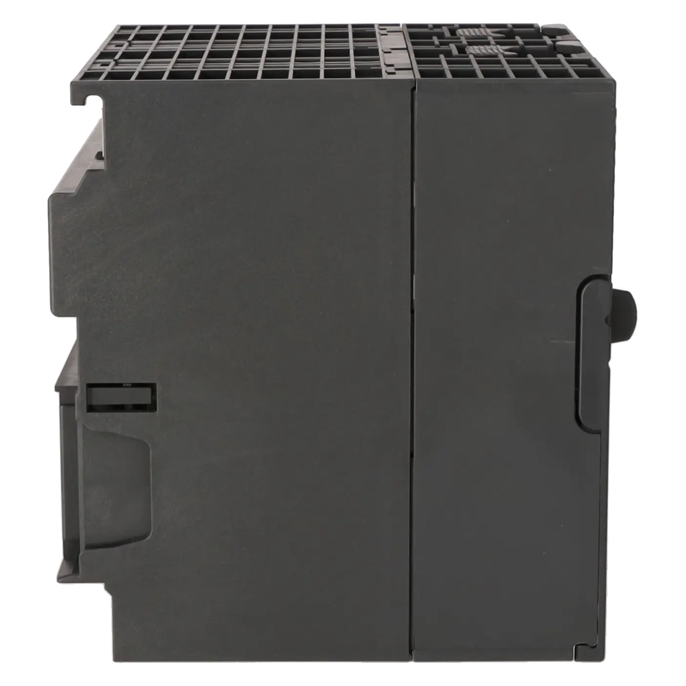
| Dimensions | |
| Width | 120 mm |
| Height | 125 mm |
| Depth | 130 mm |
| Weights | |
| Weight, approx. | 730 g |
| Fault description | Possible solution |
|---|---|
| Why does the CPU 314C-2 PN/DP remain in STOP after power-up or fail to start? | The CPU requires a SIMATIC Micro Memory Card (MMC) for operation. If the MMC is missing, empty or contains data that does not match the CPU, the controller may fail to start correctly. Also verify that the 24 V DC supply voltage is within the permitted range of 19.2 to 28.8 V DC. If the memory card is functioning correctly, perform an MRES/memory reset according to Siemens procedures and then reload the hardware configuration and user program. |
| Why is the BF LED illuminated or flashing on the CPU 314C-2 PN/DP? | On this CPU, BF indicates a bus fault. First check the physical connection to the PROFINET or PROFIBUS DP network, then verify the device name, IP address, network topology and configuration of the connected devices. After a CPU replacement, memory reset or device replacement, the BF LED often remains active if the actual installation does not match the downloaded hardware configuration. Verify the configuration in STEP 7 and reload the correct PROFINET/PROFIBUS parameters into the CPU. |
| Why is the SF LED illuminated even though the system is still partially operational? | The SF LED indicates a hardware fault or software fault. Common causes include peripheral faults, incorrectly parameterised or missing modules, I/O access errors or diagnostic events that are not being handled correctly. The CPU provides error OBs such as OB80, OB82, OB83, OB85, OB86, OB87, OB121 and OB122 for these situations. Read the diagnostic buffer, compare the configured and actual slot assignments, check parameter settings and wiring, and verify that the required error OBs are present in the project. This helps determine whether the issue is a genuine hardware fault or simply a configuration discrepancy. |
| Why is the CPU 314C-2 PN/DP not displayed correctly in STEP 7 or why can it not be configured properly? | Siemens specifies STEP 7 V5.5 with HSP 191 as the engineering requirement for this CPU. An official firmware update up to V3.3.19 is also available. If the hardware catalogue is outdated or the required Hardware Support Package (HSP) is missing, the CPU may not appear correctly or may not download consistently. Update the STEP 7 installation, verify that the HSP version matches the CPU, and then check the installed firmware version of the module. |
Is the 6ES7314-6EH04-0AB0 still available or has it already been discontinued?
The CPU clearly falls into the obsolescence and spare-parts category. Siemens classifies it as a spare part and lists its lifecycle status as Product Cancellation in the SiePortal. The EICHLER product page additionally specifies an EOP (End of Product) date of 01 October 2025. At the same time, the product page indicates that procurement is still possible through exchange units, used modules, new stock and repair services. For purchasing departments, this means that reliance on long-term series availability is no longer advisable; instead, inventory planning, exchange options and service strategies should be actively secured.
Which accessories are required to operate the CPU?
Operation requires two 40-pin front connectors and a SIMATIC Micro Memory Card (MMC). In addition, the CPU must be supplied with 24 V DC within the permitted voltage range of 19.2 to 28.8 V DC. Siemens recommends protecting the supply lines with a Type C circuit breaker rated at 2 A or higher, or a Type B circuit breaker rated at 4 A or higher. For replacement projects, it is particularly important to ensure that the MMC and front connectors are available, as otherwise even an existing spare CPU cannot be commissioned immediately.
Which software and firmware versions are relevant for engineering and service?
Siemens specifies STEP 7 V5.5 with HSP 191 for engineering. The product data lists the CPU with Firmware V3.3, and Siemens provides an official firmware update up to V3.3.19. For maintenance and service activities, this is important because many issues related to diagnostics, hardware catalogues and project downloads are caused by incompatibilities between the STEP 7 version, the installed HSP and the CPU firmware. Whenever replacement hardware is installed, these three elements should be checked together before time is spent troubleshooting field wiring or peripheral devices.
Which communication and diagnostic functions does the CPU provide in daily operation?
The CPU combines MPI/PROFIBUS DP and PROFINET within a single module and includes an integrated 2-port Ethernet switch. Siemens also specifies an integrated web server, user-defined web pages, support for up to 5 HTTP clients, NTP time synchronisation as a client, and support for device replacement without removable media. In practical operation, these features simplify diagnostics, network integration and device replacement without requiring additional communication processors. This is particularly beneficial in retrofit projects, where integration into existing network infrastructures can be achieved with reduced hardware effort and lower control cabinet space requirements.
When is repair more suitable than exchange or purchasing a replacement unit?
Repair is particularly appropriate when the system should continue operating with the original hardware platform and no project modifications are desired. An exchange unit is generally preferable when downtime must be minimised and a fully tested replacement module is required immediately. Used or new units are often selected when strategic spare-parts inventory or long-term supply security is the primary concern. Based on the service options offered by EICHLER, the decision is driven not only by cost but also by time pressure, system criticality and overall risk assessment.
Is there a direct 1:1 successor for the 6ES7314-6EH04-0AB0?
The available Siemens product documentation does not identify a clearly defined 1:1 successor for this specific compact CPU. Instead, Siemens generally recommends migration paths towards the S7-1500 platform. In official comparison scenarios, the S7-1200 CPU 1217C is also presented as a functionally related option alongside the CPU 314C-2 PN/DP. In practice, this means that replacing the CPU with a newer platform is usually a migration project rather than a plug-and-play replacement. Before proceeding, the I/O structure, communication interfaces, program scope, addressing scheme and control cabinet modifications should all be carefully evaluated.