SIEMENS 6ES7314-6BH04-0AB0
-
SIEMENS | PLC Controls | Central Processing Units
- EICHLER-art.no.: K0252208
- EAN: 4025515079118
- UPC: 040892788594
Product description
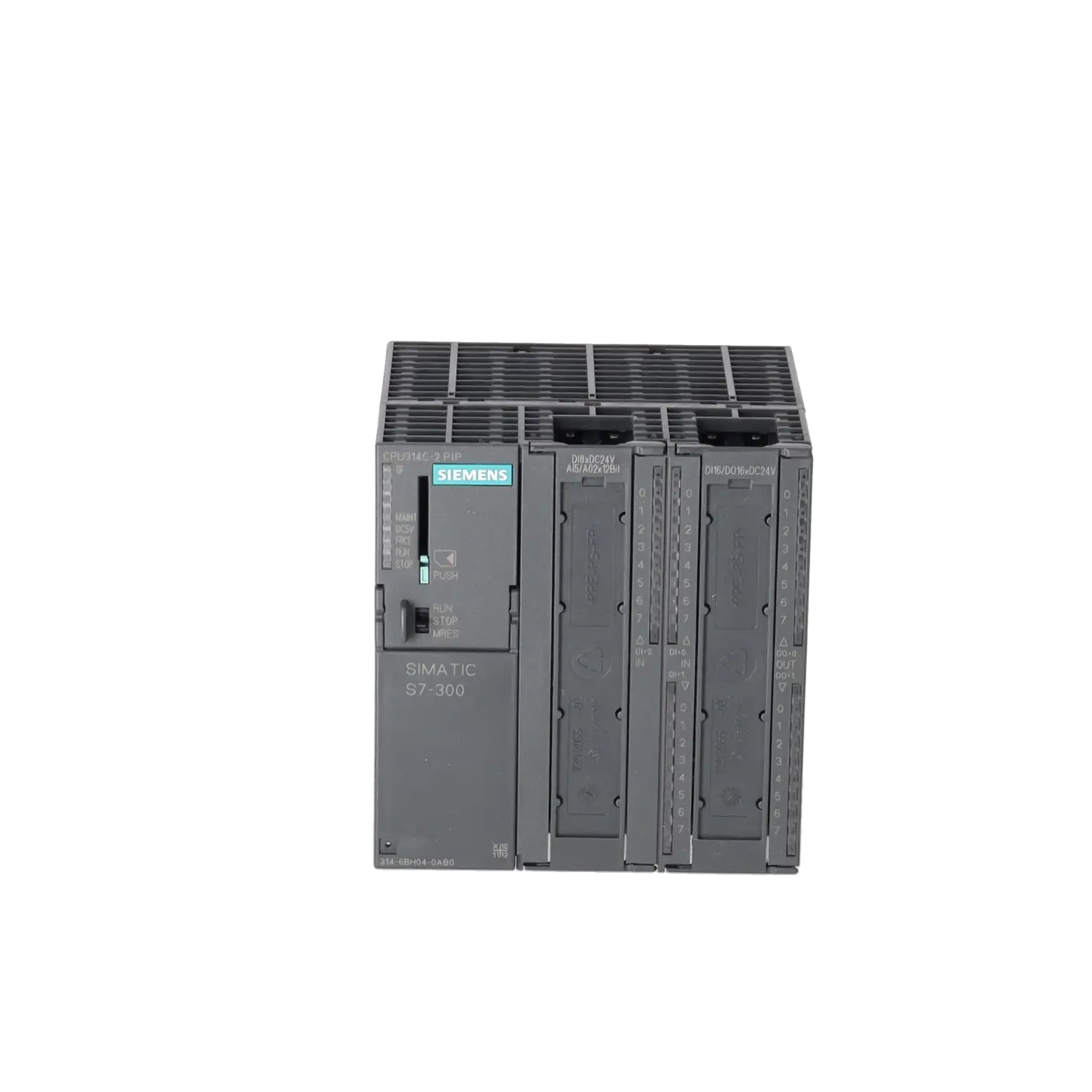
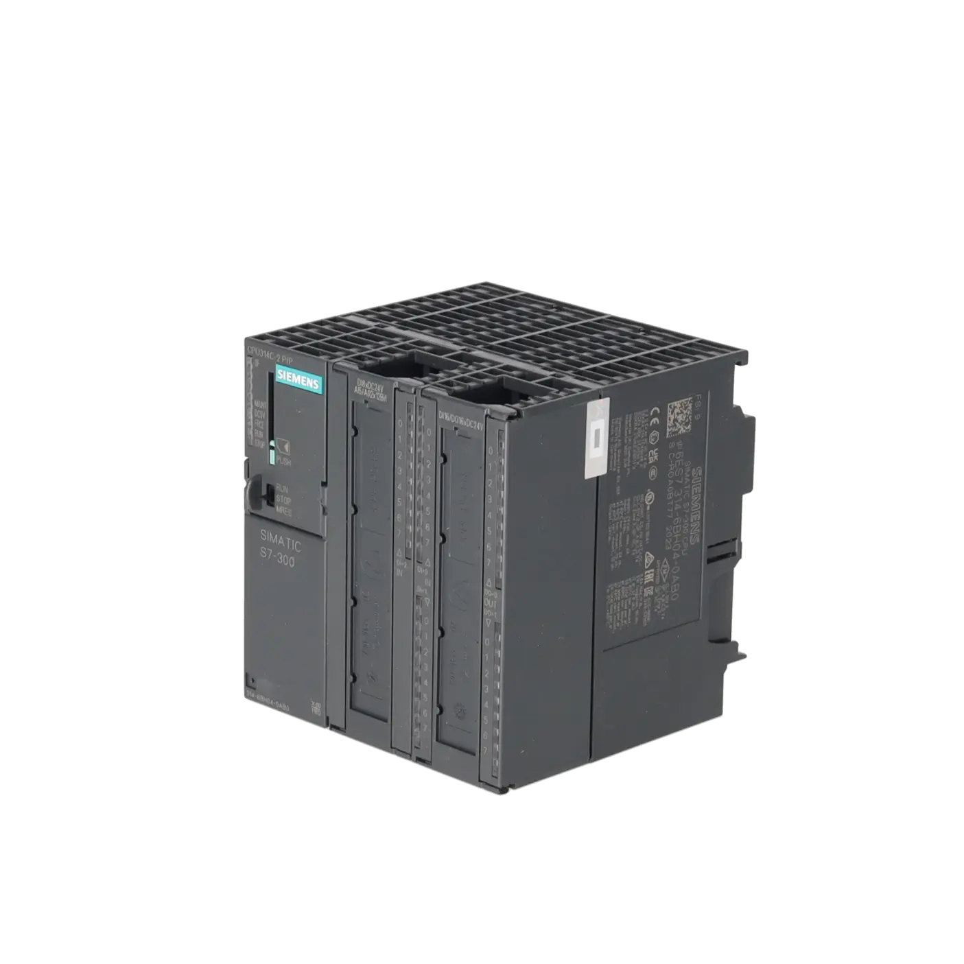
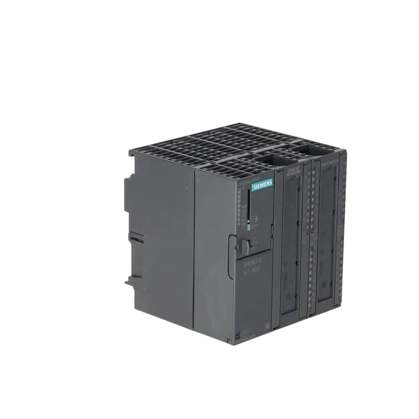
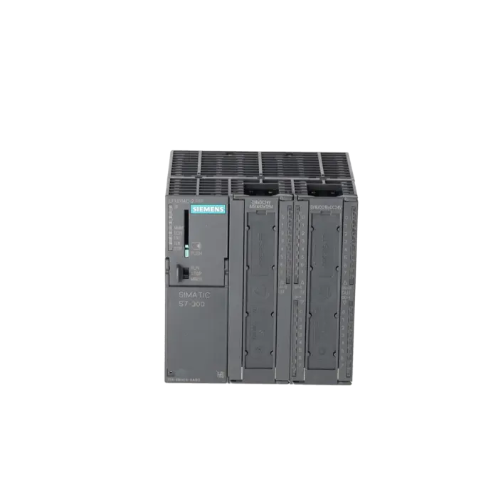
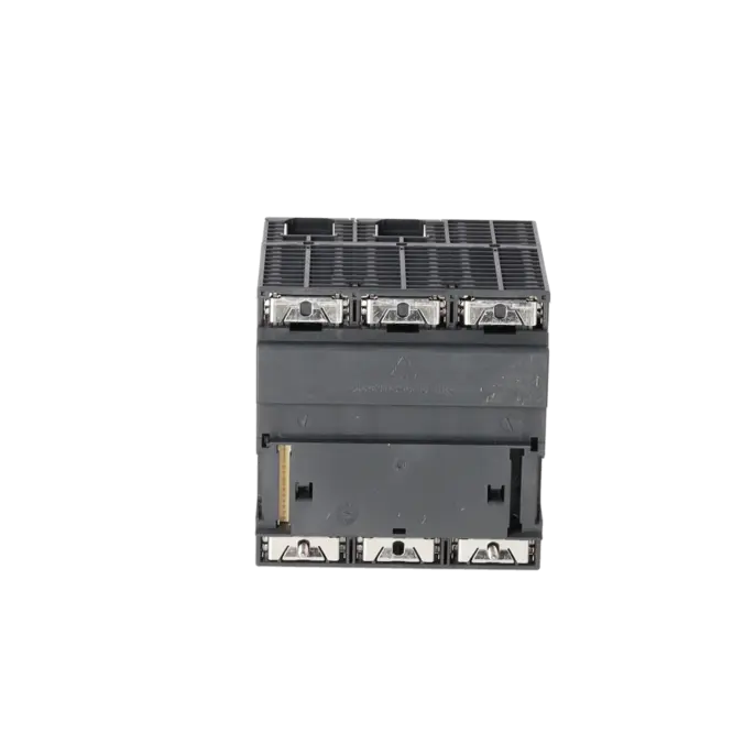
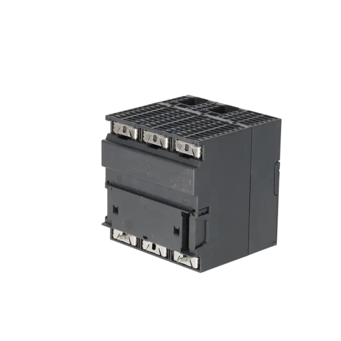
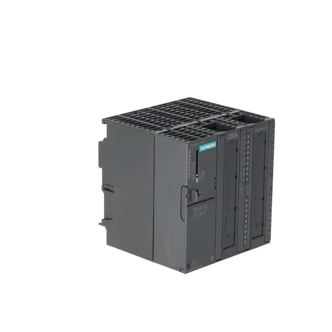
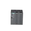
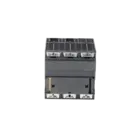
SIMATIC S7-300, CPU 314C-2 PTP COMPACT CPU WITH MPI, 24 DI/16 DO, 4 AI, 2 AO, 1 PT100, 4 HIGH-SPEED COUNTERS (60 KHZ), INTEGRATED INTERFACE RS485, INTEGR. POWER SUPPLY 24 V DC, WORK MEMORY 192 KB, FRONT CONNECTOR (2X 40-POLE) AND MICRO MEMORY CARD REQUIRE
Services for SIEMENS 6ES7314-6BH04-0AB0
Repair
from 1.392,96 €
to 2.048,48 €
Replacement
Used
New
2.731,30 €
2.048,47 €
SIEMENS |
6ES7314-6BH04-0AB0 –
additional product information
| Delivery information | |||
|---|---|---|---|
| Export identifier | AL: N ECCN: EAR99H | ||
| Net weight | 0.73 | ||
| Quantity | 1 Stück | ||
| Packaging quantity | 1 | ||
| Additional product information | |||
|---|---|---|---|
| Product status | EOP: 2025-10-01 | ||
| EAN | 4025515079118 | ||
| UPC | 040892788594 | ||
| Static lot number | 85371091 | ||
| List indicator | ST73 | ||
| Product group | 4256 | ||
| Country of origin | DE | ||
| Compliance with the substance restrictions according to RoHS directive | Since: 20110913 | ||
| Product classifications | Version | Classification | |
|---|---|---|---|
| eClass | 4 | / | |
| eClass | 5.1 | 27-24-22-07 | |
| eClass | 6.0 | 27-24-22-07 | |
| ETIM | 3 | / | |
| ETIM | 4 | EC000236 | |
| ETIM | 5 | EC000236 | |
What is the 6ES7314-6BH04-0AB0 and where is it used?
The 6ES7314-6BH04-0AB0 is a SIEMENS SIMATIC S7-300 CPU 314C-2 PtP. It combines PLC functionality, integrated digital and analogue I/O, a Pt100 input channel and a serial point-to-point communication interface within a single compact module.
This makes it particularly suitable for machines and existing installations where control cabinet space is limited and serial devices must be connected directly. Typical applications include compact automation systems with local I/O, counting functions and serial communication with devices such as barcode scanners, printers, weighing systems and other serial equipment. The integrated PtP interface supports the communication protocols ASCII, 3964(R) and RK512.
Overview of the most important technical data and what it means
The CPU operates from a 24 V DC supply and supports an input voltage range of 19.2 to 28.8 V DC. It provides 192 KB of work memory. The load memory is not integrated into the CPU but is stored on a Micro Memory Card (MMC) with support for capacities up to 8 MB.
Integrated I/O includes:
- 24 digital inputs
- 16 digital outputs
- 4 analogue inputs
- 2 analogue outputs
- 1 Pt100 input
In addition, the CPU features 4 high-speed counters up to 60 kHz, making it suitable for pulse counting, measurement and basic positioning applications.
Typical execution times are 0.06 µs for bit operations and 0.12 µs for word operations, providing adequate performance for conventional S7-300 machine control applications with integrated I/O. The system can also be expanded to up to four racks.
Product status, lifecycle status and obsolescence
For operators and purchasing departments, the lifecycle status of this CPU is an important consideration. Siemens currently classifies the 6ES7314-6BH04-0AB0 as a spare part and assigns it the lifecycle status PM410: Product Cancellation. The EICHLER product page additionally lists an EOP (End of Production) date of 01 October 2025.
In practice, this means the CPU should be included in an active obsolescence and spare-parts strategy, as availability and long-term procurement become increasingly challenging.
A direct 1:1 plug-in successor is not identified in the current Siemens product documentation. Siemens instead specifies the CPU 1512C as the target platform in its migration guide for the CPU 314C-2 PtP. This should be regarded as a migration path rather than a mechanically compatible replacement.
Available EICHLER services and when they are relevant
For maintenance, purchasing and production teams, the most relevant options are repair, exchange, used units and new units.
EICHLER offers a repair service for the 6ES7314-6BH04-0AB0 with a typical turnaround time of 2–5 days. According to the product page, repairs include:
- Technical cleaning
- Preventive maintenance
- Comprehensive functional testing
- A minimum 24-month warranty
An optional test report is also available.
When production downtime must be minimised, exchange units, used modules or new stock can be utilised depending on availability. New units are currently listed with a typical delivery time of 1–3 days.
For discontinued S7-300 products in particular, these services are valuable because they help maintain system availability despite increasing obsolescence challenges. According to EICHLER, component-level repairs can also provide cost savings of up to 70% compared with purchasing new equipment.
| Attribute | Value |
|---|---|
| General information | |
| Product type designation | CPU 314C-2 PtP |
| HW functional status | 1 |
| Firmware version | V3.3 |
| Engineering with | |
| ● Programming package | STEP 7 as of V5.5 + SP1 or STEP 7 V5.3 + SP2 or higher with HSP 204 |
| Supply voltage | |
| Rated value (DC) | 24 V |
| permissible range, lower limit (DC) | 19.2 V |
| permissible range, upper limit (DC) | 28.8 V |
| external protection for power supply lines (recommendation) | Miniature circuit breaker, type C; min. 2 A; miniature circuit breaker type B, min. 4 A |
| Mains buffering | |
| ● Mains/voltage failure stored energy time | 5 ms |
| ● Repeat rate, min. | 1 s |
| Load voltage L+ | |
| Digital inputs | |
| — Rated value (DC) | 24 V |
| — Reverse polarity protection | Yes |
| Digital outputs | |
| — Rated value (DC) | 24 V |
| — Reverse polarity protection | No |
| Input current | |
| Current consumption (rated value) | 660 mA |
| Current consumption (in no-load operation), typ. | 150 mA |
| Inrush current, typ. | 5 A |
| I²t | 0.7 A²·s |
| Digital inputs | |
| ● from load voltage L+ (without load), max. | 80 mA |
| Digital outputs | |
| ● from load voltage L+, max. | 50 mA |
| Power loss | |
| Power loss, typ. | 13 W |
| Memory | |
| Work memory | |
| ● integrated | 192 kbyte |
| ● expandable | No |
| Load memory | |
| ● Plug-in (MMC) | Yes |
| ● Plug-in (MMC), max. | 8 Mbyte |
| ● Data management on MMC (after last programming), min. | 10 a |
| Backup | |
| ● present | Yes; Guaranteed by MMC (maintenance-free) |
| ● without battery | Yes; Program and data |
| CPU processing times | |
| for bit operations, typ. | 0.06 µs |
| for word operations, typ. | 0.12 µs |
| for fixed point arithmetic, typ. | 0.16 µs |
| for floating point arithmetic, typ. | 0.59 µs |
| CPU-blocks | |
| Number of blocks (total) | 1 024; (DBs, FCs, FBs); the maximum number of loadable blocks can be reduced by the MMC used. |
| DB | |
| ● Number, max. | 1 024; Number range: 1 to 16000 |
| ● Size, max. | 64 kbyte |
| FB | |
| ● Number, max. | 1 024; Number range: 0 to 7999 |
| ● Size, max. | 64 kbyte |
| FC | |
| ● Number, max. | 1 024; Number range: 0 to 7999 |
| ● Size, max. | 64 kbyte |
| OB | |
| ● Number, max. | see instruction list |
| ● Size, max. | 64 kbyte |
| ● Number of free cycle OBs | 1; OB 1 |
| ● Number of time alarm OBs | 1; OB 10 |
| ● Number of delay alarm OBs | 2; OB 20, 21 |
| ● Number of cyclic interrupt OBs | 4; OB 32, 33, 34, 35 |
| ● Number of process alarm OBs | 1; OB 40 |
| ● Number of startup OBs | 1; OB 100 |
| ● Number of asynchronous error OBs | 4; OB 80, 82, 85, 87 |
| ● Number of synchronous error OBs | 2; OB 121, 122 |
| Nesting depth | |
| ● per priority class | 16 |
| ● additional within an error OB | 4 |
| Counters, timers and their retentivity | |
| S7 counter | |
| ● Number | 256 |
| Retentivity | |
| — adjustable | Yes |
| — preset | Z 0 to Z 7 |
| Counting range | |
| — lower limit | 0 |
| — upper limit | 999 |
| IEC counter | |
| ● present | Yes |
| ● Type | SFB |
| ● Number | Unlimited (limited only by RAM capacity) |
| S7 times | |
| ● Number | 256 |
| Retentivity | |
| — adjustable | Yes |
| — preset | No retentivity |
| Time range | |
| — lower limit | 10 ms |
| — upper limit | 9 990 s |
| IEC timer | |
| ● present | Yes |
| ● Type | SFB |
| ● Number | Unlimited (limited only by RAM capacity) |
| Data areas and their retentivity | |
| Retentive data area (incl. timers, counters, flags), max. | 64 kbyte |
| Flag | |
| ● Size, max. | 256 byte |
| ● Retentivity available | Yes; MB 0 to MB 255 |
| ● Retentivity preset | MB 0 to MB 15 |
| ● Number of clock memories | 8; 1 memory byte |
| Data blocks | |
| ● Retentivity adjustable | Yes; via non-retain property on DB |
| ● Retentivity preset | Yes |
| Local data | |
| ● per priority class, max. | 32 kbyte; Max. 2048 bytes per block |
| Address area | |
| I/O address area | |
| ● Inputs | 1 024 byte |
| ● Outputs | 1 024 byte |
| of which distributed | |
| — Inputs | none |
| — Outputs | none |
| Process image | |
| ● Inputs | 1 024 byte |
| ● Outputs | 1 024 byte |
| ● Inputs, adjustable | 1 024 byte |
| ● Outputs, adjustable | 1 024 byte |
| ● Inputs, default | 128 byte |
| ● Outputs, default | 128 byte |
| Digital channels | |
| ● Inputs | 1 016 |
| — of which central | 1 016 |
| ● Outputs | 1 008 |
| — of which central | 1 008 |
| Analog channels | |
| ● Inputs | 253 |
| — of which central | 253 |
| ● Outputs | 250 |
| — of which central | 250 |
| Hardware configuration | |
| Number of expansion units, max. | 3 |
| Number of DP masters | |
| ● integrated | none |
| ● via CP | 4 |
| Number of operable FMs and CPs (recommended) | |
| ● FM | 8 |
| ● CP, PtP | 8 |
| ● CP, LAN | 10 |
| Rack | |
| ● Racks, max. | 4 |
| ● Modules per rack, max. | 8; In rack 3 max. 7 |
| Time of day | |
| Clock | |
| ● Hardware clock (real-time) | Yes |
| ● retentive and synchronizable | Yes |
| ● Backup time | 6 wk; At 40 °C ambient temperature |
| ● Deviation per day, max. | 10 s; Typ.: 2 s |
| ● Behavior of the clock following POWER-ON | Clock continues running after POWER OFF |
| ● Behavior of the clock following expiry of backup period | the clock continues at the time of day it had when power was switched off |
| Operating hours counter | |
| ● Number | 1 |
| ● Number/Number range | 0 |
| ● Range of values | 0 to 2^31 hours (when using SFC 101) |
| ● Granularity | 1 h |
| ● retentive | Yes; Must be restarted at each restart |
| Clock synchronization | |
| ● supported | Yes |
| ● to MPI, master | Yes |
| ● on MPI, device | Yes |
| ● in AS, master | Yes |
| ● in AS, device | No |
| Digital inputs | |
| Number of digital inputs | 24 |
| ● of which inputs usable for technological functions | 16 |
| integrated channels (DI) | 24 |
| Input characteristic curve in accordance with IEC 61131, type 1 | Yes |
| Number of simultaneously controllable inputs | |
| horizontal installation | |
| — up to 40 °C, max. | 24 |
| — up to 60 °C, max. | 12 |
| vertical installation | |
| — up to 40 °C, max. | 12 |
| Input voltage | |
| ● Rated value (DC) | 24 V |
| ● for signal "0" | -3 to +5V |
| ● for signal "1" | +15 to +30 V |
| Input current | |
| ● for signal "1", typ. | 8 mA |
| Input delay (for rated value of input voltage) | |
| for standard inputs | |
| — parameterizable | Yes; 0.1 / 0.3 / 3 / 15 ms (You can reconfigure the input delay of the standard inputs during program runtime. Please note that under certain circumstances your newly set filter time may not be effective until the next filter cycle.) |
| — Rated value | 3 ms |
| for technological functions | |
| — at "0" to "1", max. | 8 µs; Minimum pulse width/minimum pause between pulses at maximum counting frequency |
| Cable length | |
| ● shielded, max. | 1 000 m; 50 m for technological functions |
| ● unshielded, max. | 600 m; for technological functions: No |
| for technological functions | |
| — shielded, max. | 50 m; at maximum count frequency |
| — unshielded, max. | not allowed |
| Digital outputs | |
| Number of digital outputs | 16 |
| ● of which high-speed outputs | 4; Notice: You cannot connect the fast outputs of your CPU in parallel |
| integrated channels (DO) | 16 |
| Short-circuit protection | Yes; Clocked electronically |
| ● Response threshold, typ. | 1 A |
| Limitation of inductive shutdown voltage to | L+ (-48 V) |
| Controlling a digital input | Yes |
| Switching capacity of the outputs | |
| ● on lamp load, max. | 5 W |
| Load resistance range | |
| ● lower limit | 48 Ω |
| ● upper limit | 4 kΩ |
| Output voltage | |
| ● for signal "1", min. | L+ (-0.8 V) |
| Output current | |
| ● for signal "1" rated value | 500 mA |
| ● for signal "1" permissible range, min. | 5 mA |
| ● for signal "1" permissible range, max. | 0.6 A |
| ● for signal "1" minimum load current | 5 mA |
| ● for signal "0" residual current, max. | 0.5 mA |
| Parallel switching of two outputs | |
| ● for uprating | No |
| ● for redundant control of a load | Yes |
| Switching frequency | |
| ● with resistive load, max. | 100 Hz |
| ● with inductive load, max. | 0.5 Hz |
| ● on lamp load, max. | 100 Hz |
| ● of the pulse outputs, with resistive load, max. | 2.5 kHz |
| Total current of the outputs (per group) | |
| horizontal installation | |
| — up to 40 °C, max. | 3 A |
| — up to 60 °C, max. | 2 A |
| vertical installation | |
| — up to 40 °C, max. | 2 A |
| Cable length | |
| ● shielded, max. | 1 000 m |
| ● unshielded, max. | 600 m |
| Analog inputs | |
| Number of analog inputs | 5 |
| ● For voltage/current measurement | 4 |
| ● For resistance/resistance thermometer measurement | 1 |
| integrated channels (AI) | 5; 4x current/voltage, 1x resistance |
| permissible input voltage for current input (destruction limit), max. | 5 V; Permanent |
| permissible input voltage for voltage input (destruction limit), max. | 30 V; Permanent |
| permissible input current for voltage input (destruction limit), max. | 0.5 mA; Permanent |
| permissible input current for current input (destruction limit), max. | 50 mA; Permanent |
| Electrical input frequency, max. | 400 Hz |
| No-load voltage for resistance-type transmitter, typ. | 3.3 V |
| Constant measurement current for resistance-type transmitter, typ. | 1.25 mA |
| Technical unit for temperature measurement adjustable | Yes; Degrees Celsius / degrees Fahrenheit / Kelvin |
| Input ranges | |
| ● Voltage | Yes; ±10 V / 100 kΩ; 0 V to 10 V / 100 kΩ |
| ● Current | Yes; ±20 mA / 100 Ω; 0 mA to 20 mA / 100 Ω; 4 mA to 20 mA / 100 Ω |
| ● Resistance thermometer | Yes; Pt 100 / 10 MΩ |
| ● Resistance | Yes; 0 Ω to 600 Ω / 10 MΩ |
| Input ranges (rated values), voltages | |
| ● 0 to +10 V | Yes |
| — Input resistance (0 to 10 V) | 100 kΩ |
| Input ranges (rated values), currents | |
| ● 0 to 20 mA | Yes |
| — Input resistance (0 to 20 mA) | 100 Ω |
| ● -20 mA to +20 mA | Yes |
| — Input resistance (-20 mA to +20 mA) | 100 Ω |
| ● 4 mA to 20 mA | Yes |
| — Input resistance (4 mA to 20 mA) | 100 Ω |
| Input ranges (rated values), resistance thermometer | |
| ● Pt 100 | Yes |
| — Input resistance (Pt 100) | 10 MΩ |
| Input ranges (rated values), resistors | |
| ● 0 to 600 ohms | Yes |
| — Input resistance (0 to 600 ohms) | 10 MΩ |
| Thermocouple (TC) | |
| Temperature compensation | |
| — parameterizable | No |
| Characteristic linearization | |
| ● parameterizable | Yes; by software |
| — for resistance thermometer | Pt 100 |
| Cable length | |
| ● shielded, max. | 100 m |
| Analog outputs | |
| integrated channels (AO) | 2 |
| Voltage output, short-circuit protection | Yes |
| Voltage output, short-circuit current, max. | 55 mA |
| Current output, no-load voltage, max. | 14 V |
| Output ranges, voltage | |
| ● 0 to 10 V | Yes |
| ● -10 V to +10 V | Yes |
| Output ranges, current | |
| ● 0 to 20 mA | Yes |
| ● -20 mA to +20 mA | Yes |
| ● 4 mA to 20 mA | Yes |
| Connection of actuators | |
| ● for voltage output two-wire connection | Yes; Without compensation of the line resistances |
| ● for voltage output four-wire connection | No |
| ● for current output two-wire connection | Yes |
| Load impedance (in rated range of output) | |
| ● with voltage outputs, min. | 1 kΩ |
| ● with voltage outputs, capacitive load, max. | 0.1 µF |
| ● with current outputs, max. | 300 Ω |
| ● with current outputs, inductive load, max. | 0.1 mH |
| Destruction limits against externally applied voltages and currents | |
| ● Voltages at the outputs towards MANA | 16 V; Permanent |
| ● Current, max. | 50 mA; Permanent |
| Cable length | |
| ● shielded, max. | 200 m |
| Analog value generation for the inputs | |
| Measurement principle | Actual value encryption (successive approximation) |
| Integration and conversion time/resolution per channel | |
| ● Resolution with overrange (bit including sign), max. | 12 bit |
| ● Integration time, parameterizable | Yes; 16.6 / 20 ms |
| ● Interference voltage suppression for interference frequency f1 in Hz | 50 / 60 Hz |
| ● Time constant of the input filter | 0.38 ms |
| ● Basic execution time of the module (all channels released) | 1 ms |
| Analog value generation for the outputs | |
| Integration and conversion time/resolution per channel | |
| ● Resolution with overrange (bit including sign), max. | 12 bit |
| ● Conversion time (per channel) | 1 ms |
| Settling time | |
| ● for resistive load | 0.6 ms |
| ● for capacitive load | 1 ms |
| ● for inductive load | 0.5 ms |
| Encoder | |
| Connection of signal encoders | |
| ● for voltage measurement | Yes |
| ● for current measurement as 2-wire transducer | Yes; with external supply |
| ● for current measurement as 4-wire transducer | Yes |
| ● for resistance measurement with two-wire connection | Yes; Without compensation of the line resistances |
| ● for resistance measurement with three-wire connection | No |
| ● for resistance measurement with four-wire connection | No |
| Connectable encoders | |
| ● 2-wire sensor | Yes |
| — permissible quiescent current (2-wire sensor), max. | 1.5 mA |
| Errors/accuracies | |
| Temperature error (relative to input range), (+/-) | 0.006 %/K |
| Crosstalk between the inputs, min. | 60 dB |
| Repeat accuracy in steady state at 25 °C (relative to input range), (+/-) | 0.06 % |
| Output ripple (relative to output range, bandwidth 0 to 50 kHz), (+/-) | 0.1 % |
| Linearity error (relative to output range), (+/-) | 0.15 % |
| Temperature error (relative to output range), (+/-) | 0.01 %/K |
| Crosstalk between the outputs, min. | 60 dB |
| Repeat accuracy in steady state at 25 °C (relative to output range), (+/-) | 0.06 % |
| Operational error limit in overall temperature range | |
| ● Voltage, relative to input range, (+/-) | 1 % |
| ● Current, relative to input range, (+/-) | 1 % |
| ● Resistance, relative to input range, (+/-) | 1 % |
| ● Voltage, relative to output range, (+/-) | 1 % |
| ● Current, relative to output range, (+/-) | 1 % |
| Basic error limit (operational limit at 25 °C) | |
| ● Voltage, relative to input range, (+/-) | 0.8 %; Linearity error ±0.06 % |
| ● Current, relative to input range, (+/-) | 0.8 %; Linearity error ±0.06 % |
| ● Resistance, relative to input range, (+/-) | 0.8 %; Linearity error ±0.2 % |
| ● Resistance thermometer, relative to input range, (+/-) | 0.8 % |
| ● Voltage, relative to output range, (+/-) | 0.8 % |
| ● Current, relative to output range, (+/-) | 0.8 % |
| Interference voltage suppression for f = n x (f1 +/- 1 %), f1 = interference frequency | |
| ● Series mode interference (peak value of interference < rated value of input range), min. | 30 dB |
| ● Common mode interference, min. | 40 dB |
| Interfaces | |
| Number of PROFINET interfaces | 0 |
| Number of RS 485 interfaces | 1; MPI |
| Number of RS 422 interfaces | 1; RS 422 / 485 combined |
| Point-to-point connection | |
| ● Cable length, max. | 1 200 m |
| Integrated protocol driver | |
| — 3964 (R) | Yes |
| — ASCII | Yes |
| — RK 512 | Yes |
| Transmission rate, RS 422/485 | |
| — with 3964 (R) protocol, max. | 19.2 kbit/s; 38.4 kbit/s half duplex; 19.2 kbit/s full duplex |
| — with ASCII protocol, max. | 19.2 kbit/s; 38.4 kbit/s half duplex; 19.2 kbit/s full duplex |
| — with RK 512 protocol, max. | 19.2 kbit/s; 38.4 kbit/s half duplex; 19.2 kbit/s full duplex |
| 1. Interface | |
| Interface type | Integrated RS 485 interface |
| Isolated | No |
| Interface types | |
| ● RS 485 | Yes |
| ● Output current of the interface, max. | 200 mA |
| Protocols | |
| ● MPI | Yes |
| ● PROFIBUS DP master | No |
| ● PROFIBUS DP device | No |
| ● Point-to-point connection | No |
| MPI | |
| ● Transmission rate, max. | 187.5 kbit/s |
| Services | |
| — PG/OP communication | Yes |
| — Routing | No |
| — Global data communication | Yes |
| — S7 basic communication | Yes |
| — S7 communication | Yes; Only server, configured on one side |
| — S7 communication, as client | No; but via CP and loadable FB |
| — S7 communication, as server | Yes |
| 2. Interface | |
| Interface type | Integrated RS 422/ 485 interface |
| Isolated | Yes |
| Interface types | |
| ● RS 485 | Yes; RS 422 / 485 (X.27) |
| ● Output current of the interface, max. | No |
| Protocols | |
| ● MPI | No |
| ● PROFINET IO Controller | No |
| ● PROFINET IO Device | No |
| ● PROFINET CBA | No |
| ● PROFIBUS DP master | No |
| ● PROFIBUS DP device | No |
| ● Point-to-point connection | Yes |
| Point-to-point connection | |
| ● Transmission rate, max. | 19.2 kbit/s; 38.4 kbit/s half duplex; 19.2 kbit/s full duplex |
| ● Interface controllable from the user program | Yes |
| ● Interface can trigger alarm/interrupt in the user program | Yes; Message on break - identification |
| Protocols | |
| PROFIsafe | No |
| Communication functions | |
| PG/OP communication | Yes |
| Data record routing | No |
| Global data communication | |
| ● supported | Yes |
| ● Number of GD loops, max. | 8 |
| ● Number of GD packets, max. | 8 |
| ● Number of GD packets, transmitter, max. | 8 |
| ● Number of GD packets, receiver, max. | 8 |
| ● Size of GD packets, max. | 22 byte |
| ● Size of GD packet (of which consistent), max. | 22 byte |
| S7 basic communication | |
| ● supported | Yes |
| ● User data per job, max. | 76 byte |
| ● User data per job (of which consistent), max. | 76 byte; 76 bytes (with X_SEND or X_RCV); 64 bytes (with X_PUT or X_GET as server) |
| S7 communication | |
| ● supported | Yes |
| ● as server | Yes |
| ● as client | Yes; Via CP and loadable FB |
| ● User data per job, max. | 180 kbyte; With PUT/GET |
| ● User data per job (of which consistent), max. | 240 byte; as server |
| S5 compatible communication | |
| ● supported | Yes; via CP and loadable FC |
| Number of connections | |
| ● overall | 12 |
| ● usable for PG communication | 11 |
| — reserved for PG communication | 1 |
| — adjustable for PG communication, min. | 1 |
| — adjustable for PG communication, max. | 11 |
| ● usable for OP communication | 11 |
| — reserved for OP communication | 1 |
| — adjustable for OP communication, min. | 1 |
| — adjustable for OP communication, max. | 11 |
| ● usable for S7 basic communication | 8 |
| — reserved for S7 basic communication | 0 |
| — adjustable for S7 basic communication, min. | 0 |
| — adjustable for S7 basic communication, max. | 8 |
| S7 message functions | |
| Number of login stations for message functions, max. | 12; Depending on the configured connections for PG/OP and S7 basic communication |
| Process diagnostic messages | Yes |
| simultaneously active Alarm_S blocks, max. | 300 |
| Test commissioning functions | |
| Status block | Yes; Up to 2 simultaneously |
| Single step | Yes |
| Number of breakpoints | 4 |
| Status/control | |
| ● Status/control variable | Yes |
| ● Variables | Inputs, outputs, memory bits, DB, times, counters |
| ● Number of variables, max. | 30 |
| — of which status variables, max. | 30 |
| — of which control variables, max. | 14 |
| Forcing | |
| ● Forcing | Yes |
| ● Forcing, variables | Inputs, outputs |
| ● Number of variables, max. | 10 |
| Diagnostic buffer | |
| ● present | Yes |
| ● Number of entries, max. | 500 |
| — adjustable | No |
| — of which powerfail-proof | 100; Only the last 100 entries are retained |
| ● Number of entries readable in RUN, max. | 499 |
| — adjustable | Yes; From 10 to 499 |
| — preset | 10 |
| Service data | |
| ● can be read out | Yes |
| Interrupts/diagnostics/status information | |
| Diagnostics indication LED | |
| ● Status indicator digital input (green) | Yes |
| ● Status indicator digital output (green) | Yes |
| Integrated Functions | |
| Counter | |
| ● Number of counters | 4; See "Technological Functions" manual |
| ● Counting frequency, max. | 60 kHz |
| Frequency measurement | Yes |
| ● Number of frequency meters | 4; up to 60 kHz (see "Technological Functions" manual) |
| controlled positioning | Yes |
| integrated function blocks (closed-loop control) | Yes; PID controller (see "Technological Functions" manual) |
| PID controller | Yes |
| Number of pulse outputs | 4; Pulse width modulation up to 2.5 kHz (see "Technological Functions" Manual) |
| Limit frequency (pulse) | 2.5 kHz |
| Potential separation | |
| Potential separation digital inputs | |
| ● Potential separation digital inputs | Yes |
| ● between the channels | No |
| ● between the channels and backplane bus | Yes |
| Potential separation digital outputs | |
| ● Potential separation digital outputs | Yes |
| ● between the channels | Yes |
| ● between the channels, in groups of | 8 |
| ● between the channels and backplane bus | Yes |
| Potential separation analog inputs | |
| ● Potential separation analog inputs | Yes; common for analog I/O |
| ● between the channels | No |
| ● between the channels and backplane bus | Yes |
| Potential separation analog outputs | |
| ● Potential separation analog outputs | Yes; common for analog I/O |
| ● between the channels | No |
| ● between the channels and backplane bus | Yes |
| Isolation | |
| Isolation tested with | 600 V DC |
| Ambient conditions | |
| Ambient temperature during operation | |
| ● min. | 0 °C |
| ● max. | 60 °C |
| Configuration | |
| Configuration software | |
| ● STEP 7 | Yes; STEP 7 V5.5 + SP1 or higher or STEP 7 V5.3 + SP2 or higher with HSP 203 |
| ● STEP 7 Lite | No |
| Programming | |
| ● Command set | see instruction list |
| ● Nesting levels | 8 |
| ● System functions (SFC) | see instruction list |
| ● System function blocks (SFB) | see instruction list |
| Programming language | |
| — LAD | Yes |
| — FBD | Yes |
| — STL | Yes |
| — SCL | Yes |
| — CFC | Yes |
| — GRAPH | Yes |
| — HiGraph® | Yes |
| Know-how protection | |
| ● User program protection/password protection | Yes |
| ● Block encryption | Yes; With S7 block Privacy |
| Dimensions | |
| Width | 120 mm |
| Height | 125 mm |
| Depth | 130 mm |
| Weights | |
| Weight, approx. | 680 g |
| Fault description | Possible solution |
|---|---|
| Why is the STOP LED flashing on the CPU 314C-2 PtP and the controller will not start? | First check whether a SIMATIC Micro Memory Card (MMC) is correctly inserted. This CPU requires an MMC for operation. After initial commissioning or after replacing the memory card, the CPU automatically performs a memory reset (MRES) during start-up. If the CPU remains in STOP, perform the memory reset again correctly and then reload the hardware configuration and user program. |
| Why can't I establish an MPI connection to the 6ES7314-6BH04-0AB0? | Check the PG/PC interface settings, the bus connector and the address configuration. During commissioning, forum references for this CPU indicate the factory default MPI address 2. The CPU must also be supplied with a complete 24 V DC power supply, and the Micro Memory Card must be present. Only then should the hardware configuration be downloaded and the connection tested again. |
| Why is the SF LED on the CPU 314C-2 PtP illuminated red? | On the CPU 31xC series, the SF LED indicates a hardware or software fault. The fastest way to identify the cause is to read the diagnostic buffer in STEP 7, where the CPU stores the fault information in plain text. Only after evaluating the diagnostic buffer should you determine whether the issue originates from the project configuration, peripheral devices, memory contents or a hardware defect within the module itself. |
| Why is the serial RS485/PtP communication on interface X2 not working? | Verify that the correct communication protocol has been configured for the PtP channel. The CPU 314C-2 PtP supports ASCII, 3964(R) and RK512. In RS485 half-duplex mode, only one device may transmit at a time; otherwise telegrams can become corrupted. Communication problems are often caused by incorrect interface parameters, an unsuitable network topology or missing processing of received strings within the PLC program. |
| Why is the 6ES7314-6BH04-0AB0 not recognised correctly or not configured properly in STEP 7? | Check the installed STEP 7 version. Siemens specifies STEP 7 V5.5 + SP1 or higher, or STEP 7 V5.3 + SP2 with HSP 204 for this hardware generation. If the engineering software is too old or the required Hardware Support Package (HSP) is missing, the CPU may not appear correctly in the hardware catalogue or may be represented incorrectly. After updating the software environment, reload the hardware configuration to the CPU. |
Does the 6ES7314-6BH04-0AB0 require a Micro Memory Card?
Yes. The CPU has no integrated load memory, so a SIMATIC Micro Memory Card (MMC) is required for normal operation. Siemens also states that after the first power-up with an inserted MMC, the CPU automatically performs a memory reset (MRES) and then remains in STOP until the hardware configuration and user program have been loaded. For operators, this is important because many start-up problems with S7-300 compact CPUs are caused by a missing, incompatible or incorrectly inserted MMC.
What interfaces and communication options does the CPU 314C-2 PtP provide?
The module combines MPI for engineering and service access with an integrated PtP interface based on RS422/RS485 for serial device communication. Via this PtP interface, the CPU supports ASCII, 3964(R) and RK512 protocols. This makes it particularly suitable for existing machines where serial third-party devices need to be connected without an additional communication processor. Correct configuration of the protocol, baud rate and operating mode is essential, as the interface can be operated as either RS422 or RS485, depending on the application.
Which STEP 7 version is required for configuration and service?
For the 6ES7314-6BH04-0AB0, Siemens specifies STEP 7 V5.5 + SP1 or higher, or STEP 7 V5.3 + SP2 with HSP 204. This requirement is important for both purchasing and maintenance because an available replacement CPU is of little use if the existing engineering environment does not support it correctly. Before service work or migrations, always verify that the required Hardware Support Package (HSP) is installed on the engineering workstation.
Is the CPU still an active product or only available as a spare part?
The current situation clearly points to obsolescence management. Siemens lists the CPU as a spare part and assigns it the lifecycle status PM410: Product Cancellation. In addition, EICHLER lists an EOP (End of Product) date of 01.10.2025. For operators, this means the CPU is no longer a future-oriented product but rather a component that should be supported through repair strategies, spare-part stocking, exchange concepts and migration planning to minimise the risk of unplanned downtime.
Is there an official successor to the 6ES7314-6BH04-0AB0?
No officially designated plug-compatible successor is listed in the current Siemens product information. However, the official Siemens migration guide identifies the CPU 1512C as the target platform for migrating from the CPU 314C-2 PtP. This is important for decision-makers because it is not a simple 1:1 rack replacement, but rather a migration to the S7-1500 platform, which may require adaptations to the application, communication concept and, in some cases, the peripheral hardware.
When is repair more economical than purchasing a new or replacement unit?
Repair is often the most economical option when the machine must be returned to service quickly, the existing architecture should remain unchanged and migration to a new control platform is not currently feasible. For the 6ES7314-6BH04-0AB0, EICHLER offers repair with a typical turnaround time of 2–5 days, including technical cleaning, preventive maintenance, comprehensive functional testing and a minimum 24-month warranty. EICHLER also states that repairs can provide up to 70% cost savings compared with purchasing a new unit. For discontinued S7-300 modules, repair is frequently the most practical way to reduce production risks and maintain system availability.