SIEMENS 6ES7314-1AG14-0AB0
-
SIEMENS | PLC Controls | Central Processing Units
- EICHLER-art.no.: K0227611
- EAN: 4025515077695
- UPC: 040892550290
Product description
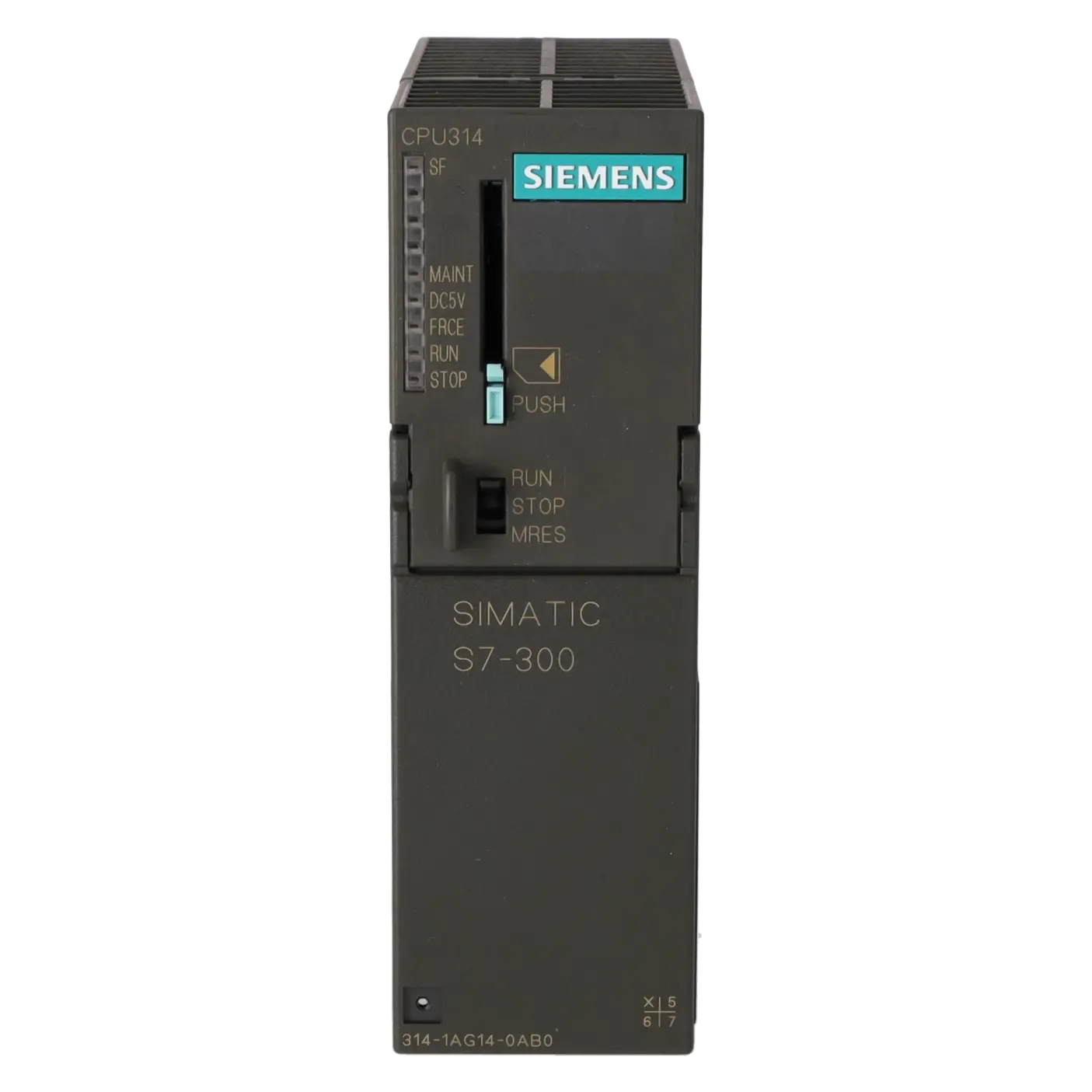
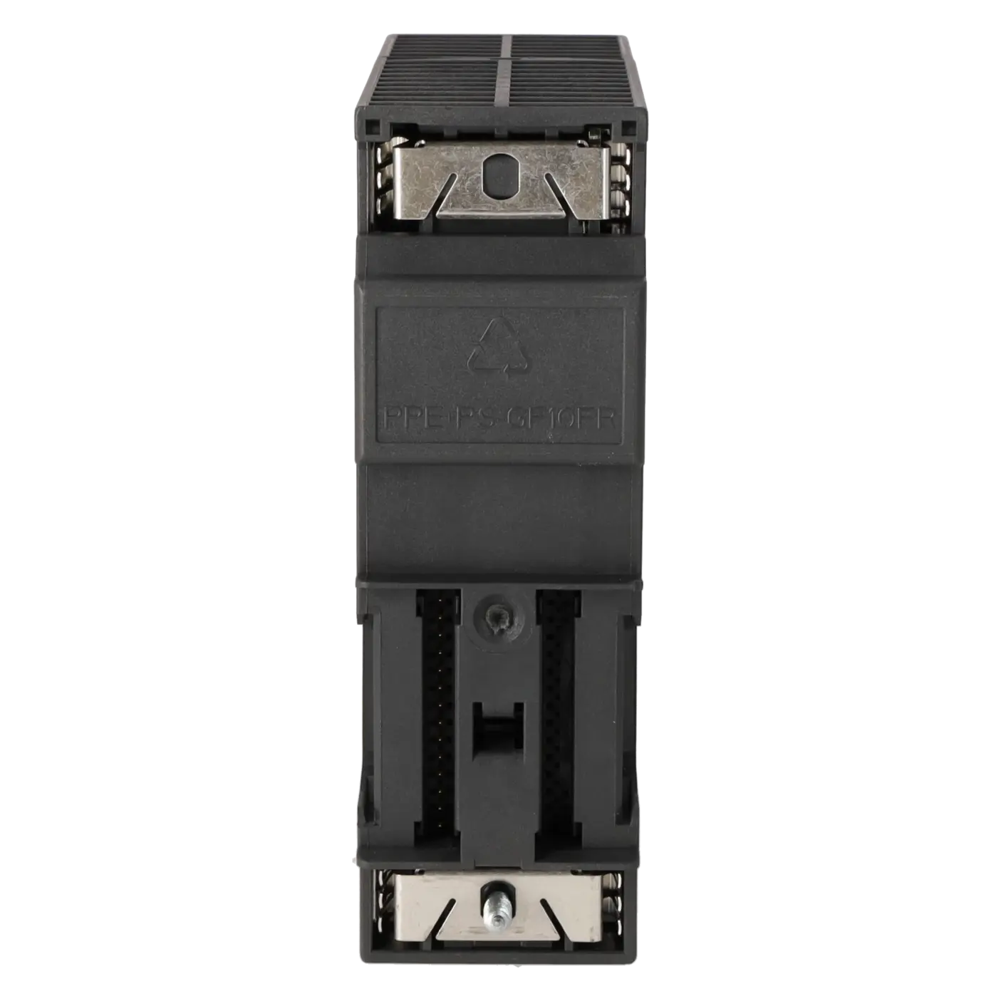
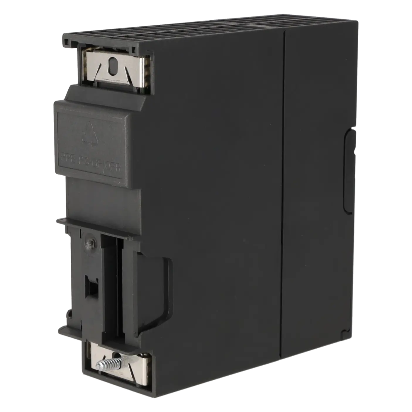
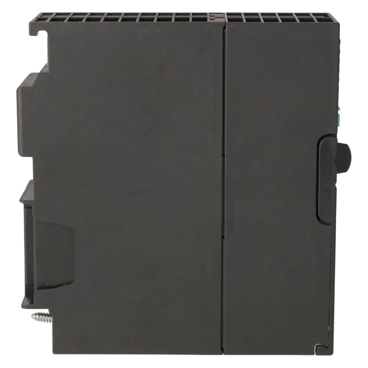
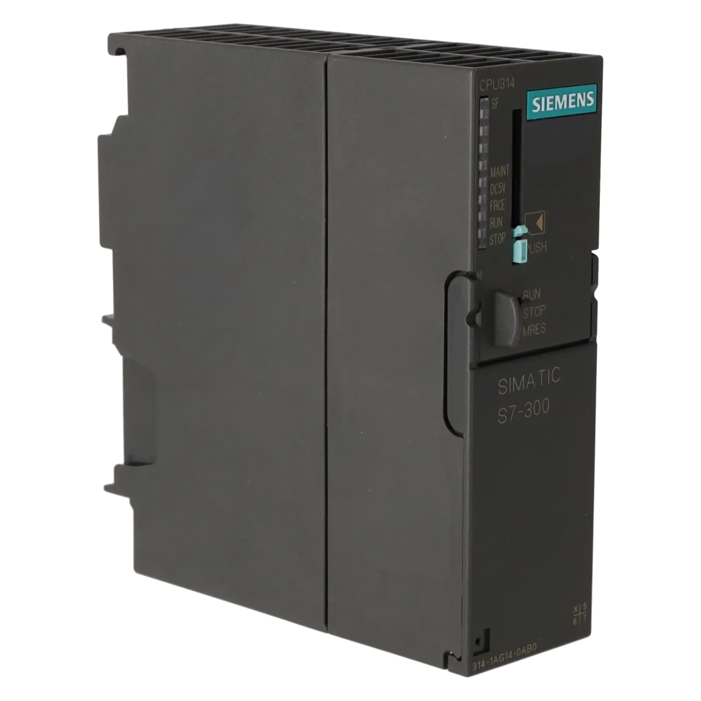
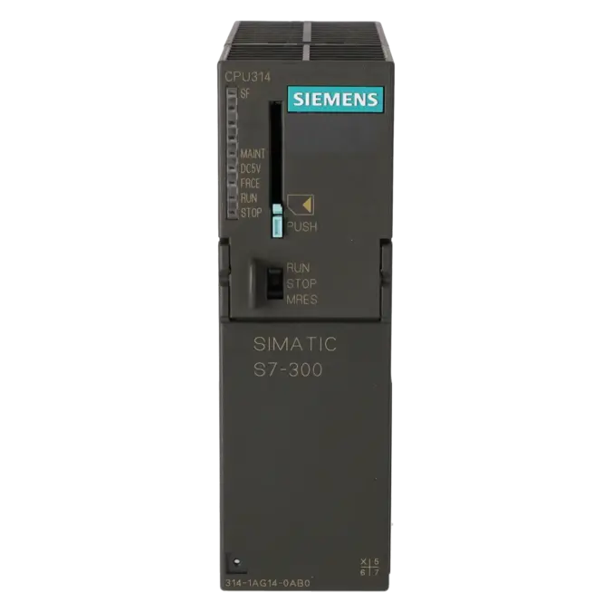
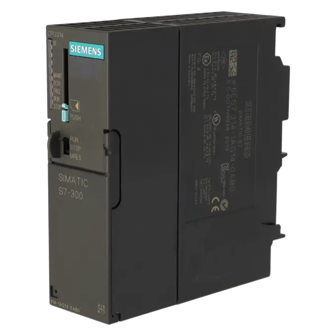
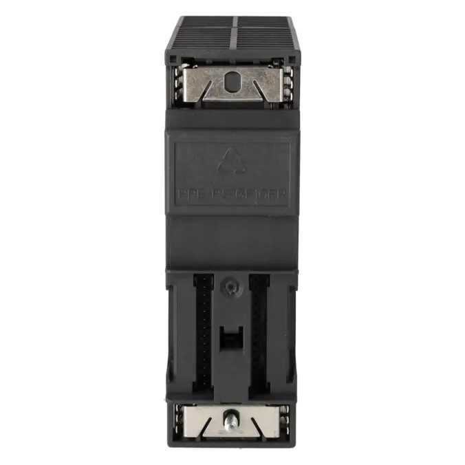
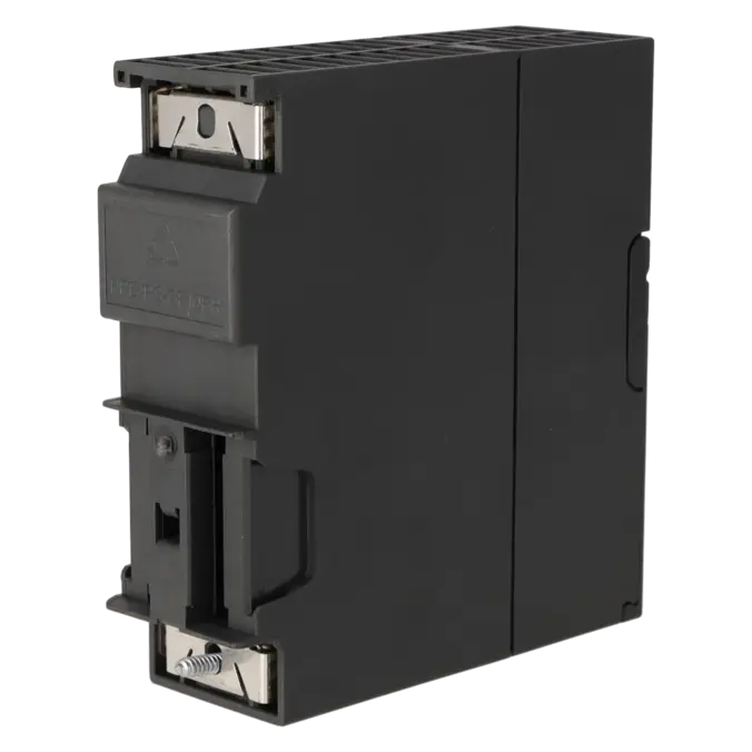
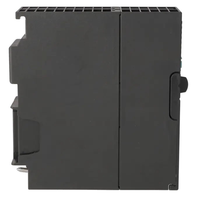
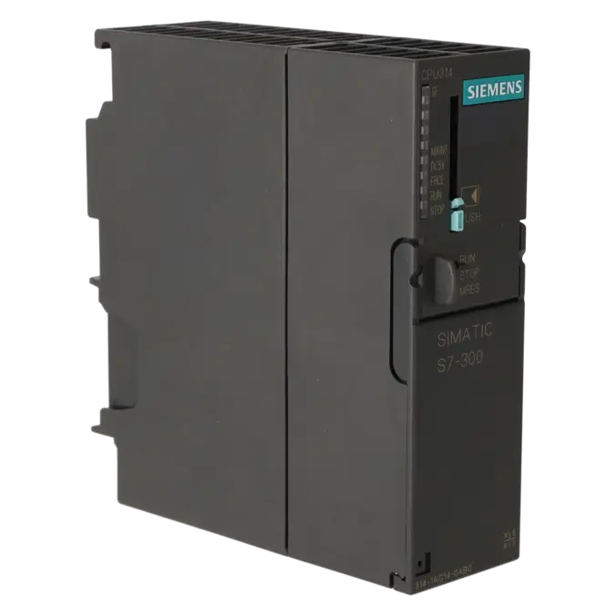
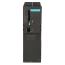
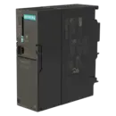
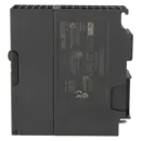
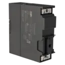
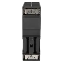
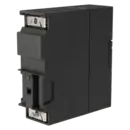
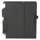
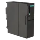
SIMATIC S7-300, CPU 314 CENTRAL PROCESSING UNIT WITH MPI, INTEGR. POWER SUPPLY 24 V DC, WORK MEMORY 128 KB, MICRO MEMORY CARD REQUIRED
Services for SIEMENS 6ES7314-1AG14-0AB0
Repair
from 504,05 €
to 907,28 €
Replacement
667,59 €
500,69 €
Used
936,32 €
702,24 €
New
1.127,50 €
845,62 €
SIEMENS |
6ES7314-1AG14-0AB0 –
additional product information
| Delivery information | |||
|---|---|---|---|
| Export identifier | AL: N ECCN: EAR99H | ||
| Net weight | 0.315 | ||
| Quantity | 1 Stück | ||
| Packaging quantity | 1 | ||
| Additional product information | |||
|---|---|---|---|
| Product status | |||
| EAN | 4025515077695 | ||
| UPC | 040892550290 | ||
| Static lot number | 85371091 | ||
| List indicator | ST73 | ||
| Product group | 4256 | ||
| Country of origin | DE | ||
| Compliance with the substance restrictions according to RoHS directive | Since: 20091125 | ||
| Product classifications | Version | Classification | |
|---|---|---|---|
| eClass | 4 | 27-24-03-02 | |
| eClass | 5.1 | 27-24-22-07 | |
| eClass | 6.0 | 27-24-22-07 | |
| ETIM | 3 | / | |
| ETIM | 4 | EC000236 | |
| ETIM | 5 | EC000236 | |
What is the 6ES7314-1AG14-0AB0 and where is it used
The 6ES7314-1AG14-0AB0 is a SIMATIC S7-300 CPU 314 from Siemens. It is a central PLC module with an integrated 24 V DC power supply and an MPI interface for classic automation tasks in machine building and industrial systems. The CPU is typically used in existing installations where robust control logic, proven STEP 7 engineering environments and a long-term maintainable S7-300 architecture are required. Typical application areas include production lines, conveyor systems, packaging machines, special-purpose machinery and retrofit projects. For maintenance teams, the module is particularly important when existing S7-300 systems need to be restored quickly or repaired without redesigning the entire control architecture.
Overview of the key technical data and what it means
The CPU 314 operates on 24 V DC, requires a SIMATIC Micro Memory Card (MMC) and provides 128 KB of work memory. In practice, this offers sufficient resources for typical S7-300 control tasks, although without the reserves of modern high-end CPUs. The integrated MPI/RS485 interface supports up to 187.5 kbit/s and is suitable for PG/OP communication, global data exchange and S7 communication within existing networks. The load memory is implemented via a removable MMC and supports capacities of up to 8 MB. In addition, the CPU provides 1,024 bytes of inputs, 1,024 bytes of outputs, a battery-backed real-time clock, a diagnostic buffer with up to 500 entries and expansion options via multiple racks. For purchasing and engineering departments, it is important to note that the CPU is compact, well established and designed for classic S7-300 topologies rather than native PROFINET architectures.
Product status, life-cycle status and obsolescence
For operators of existing systems, the product status is particularly important. Siemens currently lists the 6ES7314-1AG14-0AB0 as a Spare Part and specifies the lifecycle status PM410: Product Cancellation, effective from 01.10.2025. This clearly indicates that the CPU is no longer a future-oriented standard choice for new projects, although it remains highly relevant for maintaining existing installations. As S7-300 systems approach obsolescence, support through repair services, exchange units and spare-parts stock strategies becomes increasingly important. Siemens does not identify a direct plug-compatible successor within the active S7-300 product range; however, the official migration guide identifies the CPU 1511 (6ES7511-1AK01-0AB0) as the migration target for the CPU 314.
Available EICHLER services and when they are relevant
For operators of existing S7-300 systems, four scenarios are particularly relevant for the 6ES7314-1AG14-0AB0: repair, exchange, used units and new units. Repair is especially attractive when the system should continue operating without modification and the original module can be economically restored. According to EICHLER, repairs include technical cleaning, preventive maintenance, comprehensive functional testing and a minimum 24-month warranty. An exchange unit is beneficial when downtime must be minimised and a fully tested replacement is required quickly. Used and new units allow purchasing departments to choose an appropriate procurement strategy based on budget, delivery requirements and risk profile. An optional test report further supports documentation, quality assurance and internal approval processes.
| Attribute | Value |
|---|---|
| General information | |
| Product type designation | CPU 314 |
| HW functional status | 1 |
| Firmware version | V3.3 |
| Engineering with | |
| ● Programming package | STEP 7 V5.5 + SP1 or higher or STEP 7 V5.2 + SP1 or higher with HSP 218 |
| Supply voltage | |
| Rated value (DC) | 24 V |
| permissible range, lower limit (DC) | 19.2 V |
| permissible range, upper limit (DC) | 28.8 V |
| external protection for power supply lines (recommendation) | 2 A min. |
| Mains buffering | |
| ● Mains/voltage failure stored energy time | 5 ms |
| ● Repeat rate, min. | 1 s |
| Input current | |
| Current consumption (rated value) | 650 mA |
| Current consumption (in no-load operation), typ. | 140 mA |
| Inrush current, typ. | 3.5 A |
| I²t | 1 A²·s |
| Power loss | |
| Power loss, typ. | 4 W |
| Memory | |
| Work memory | |
| ● integrated | 128 kbyte |
| ● expandable | No |
| Load memory | |
| ● Plug-in (MMC) | Yes |
| ● Plug-in (MMC), max. | 8 Mbyte |
| ● Data management on MMC (after last programming), min. | 10 a |
| Backup | |
| ● present | Yes; Guaranteed by MMC (maintenance-free) |
| ● without battery | Yes; Program and data |
| CPU processing times | |
| for bit operations, typ. | 0.06 µs |
| for word operations, typ. | 0.12 µs |
| for fixed point arithmetic, typ. | 0.16 µs |
| for floating point arithmetic, typ. | 0.59 µs |
| CPU-blocks | |
| Number of blocks (total) | 1 024; (DBs, FCs, FBs); the maximum number of loadable blocks can be reduced by the MMC used. |
| DB | |
| ● Number, max. | 1 024; Number range: 1 to 16000 |
| ● Size, max. | 64 kbyte |
| FB | |
| ● Number, max. | 1 024; Number range: 0 to 7999 |
| ● Size, max. | 64 kbyte |
| FC | |
| ● Number, max. | 1 024; Number range: 0 to 7999 |
| ● Size, max. | 64 kbyte |
| OB | |
| ● Number, max. | see instruction list |
| ● Size, max. | 64 kbyte |
| ● Number of free cycle OBs | 1; OB 1 |
| ● Number of time alarm OBs | 1; OB 10 |
| ● Number of delay alarm OBs | 2; OB 20, 21 |
| ● Number of cyclic interrupt OBs | 4; OB 32, 33, 34, 35 |
| ● Number of process alarm OBs | 1; OB 40 |
| ● Number of startup OBs | 1; OB 100 |
| ● Number of asynchronous error OBs | 4; OB 80, 82, 85, 87 |
| ● Number of synchronous error OBs | 2; OB 121, 122 |
| Nesting depth | |
| ● per priority class | 16 |
| ● additional within an error OB | 4 |
| Counters, timers and their retentivity | |
| S7 counter | |
| ● Number | 256 |
| Retentivity | |
| — adjustable | Yes |
| — preset | Z 0 to Z 7 |
| Counting range | |
| — lower limit | 0 |
| — upper limit | 999 |
| IEC counter | |
| ● present | Yes |
| ● Type | SFB |
| ● Number | Unlimited (limited only by RAM capacity) |
| S7 times | |
| ● Number | 256 |
| Retentivity | |
| — adjustable | Yes |
| — preset | No retentivity |
| Time range | |
| — lower limit | 10 ms |
| — upper limit | 9 990 s |
| IEC timer | |
| ● present | Yes |
| ● Type | SFB |
| ● Number | Unlimited (limited only by RAM capacity) |
| Data areas and their retentivity | |
| Retentive data area (incl. timers, counters, flags), max. | 64 kbyte |
| Flag | |
| ● Size, max. | 256 byte |
| ● Retentivity available | Yes; MB 0 to MB 255 |
| ● Retentivity preset | MB 0 to MB 15 |
| ● Number of clock memories | 8; 1 memory byte |
| Data blocks | |
| ● Retentivity adjustable | Yes; via non-retain property on DB |
| ● Retentivity preset | Yes |
| Local data | |
| ● per priority class, max. | 32 kbyte; Max. 2 KB per block |
| Address area | |
| I/O address area | |
| ● Inputs | 1 024 byte |
| ● Outputs | 1 024 byte |
| Process image | |
| ● Inputs | 1 024 byte |
| ● Outputs | 1 024 byte |
| ● Inputs, adjustable | 1 024 byte |
| ● Outputs, adjustable | 1 024 byte |
| ● Inputs, default | 128 byte |
| ● Outputs, default | 128 byte |
| Digital channels | |
| ● Inputs | 1 024 |
| — of which central | 1 024 |
| ● Outputs | 1 024 |
| — of which central | 1 024 |
| Analog channels | |
| ● Inputs | 256 |
| — of which central | 256 |
| ● Outputs | 256 |
| — of which central | 256 |
| Hardware configuration | |
| Number of expansion units, max. | 3 |
| Number of DP masters | |
| ● integrated | 0 |
| ● via CP | 4 |
| Number of operable FMs and CPs (recommended) | |
| ● FM | 8 |
| ● CP, PtP | 8 |
| ● CP, LAN | 10 |
| Rack | |
| ● Racks, max. | 4 |
| ● Modules per rack, max. | 8 |
| Time of day | |
| Clock | |
| ● Hardware clock (real-time) | Yes |
| ● retentive and synchronizable | Yes |
| ● Backup time | 6 wk; At 40 °C ambient temperature |
| ● Deviation per day, max. | 10 s; Typ.: 2 s |
| ● Behavior of the clock following POWER-ON | Clock continues running after POWER OFF |
| ● Behavior of the clock following expiry of backup period | the clock continues at the time of day it had when power was switched off |
| Operating hours counter | |
| ● Number | 1 |
| ● Number/Number range | 0 |
| ● Range of values | 0 to 2^31 hours (when using SFC 101) |
| ● Granularity | 1 h |
| ● retentive | Yes; Must be restarted at each restart |
| Clock synchronization | |
| ● supported | Yes |
| ● to MPI, master | Yes |
| ● on MPI, device | Yes |
| ● in AS, master | Yes |
| ● in AS, device | No |
| Digital inputs | |
| Number of digital inputs | 0 |
| Digital outputs | |
| Number of digital outputs | 0 |
| Analog inputs | |
| Number of analog inputs | 0 |
| Interfaces | |
| Number of PROFINET interfaces | 0 |
| Number of RS 485 interfaces | 1; MPI |
| Number of RS 422 interfaces | 0 |
| 1. Interface | |
| Interface type | Integrated RS 485 interface |
| Isolated | No |
| Interface types | |
| ● RS 485 | Yes |
| ● Output current of the interface, max. | 200 mA |
| Protocols | |
| ● MPI | Yes |
| ● PROFIBUS DP master | No |
| ● PROFIBUS DP device | No |
| ● Point-to-point connection | No |
| MPI | |
| ● Transmission rate, max. | 187.5 kbit/s |
| Services | |
| — PG/OP communication | Yes |
| — Routing | No |
| — Global data communication | Yes |
| — S7 basic communication | Yes |
| — S7 communication | Yes; Only server, configured on one side |
| — S7 communication, as client | No |
| — S7 communication, as server | Yes |
| Protocols | |
| PROFIsafe | No |
| Communication functions | |
| PG/OP communication | Yes |
| Data record routing | No |
| Global data communication | |
| ● supported | Yes |
| ● Number of GD loops, max. | 8 |
| ● Number of GD packets, max. | 8 |
| ● Number of GD packets, transmitter, max. | 8 |
| ● Number of GD packets, receiver, max. | 8 |
| ● Size of GD packets, max. | 22 byte |
| ● Size of GD packet (of which consistent), max. | 22 byte |
| S7 basic communication | |
| ● supported | Yes |
| ● User data per job, max. | 76 byte |
| ● User data per job (of which consistent), max. | 76 byte; 76 bytes (with X_SEND or X_RCV); 64 bytes (with X_PUT or X_GET as server) |
| S7 communication | |
| ● supported | Yes |
| ● as server | Yes |
| ● as client | Yes; Via CP and loadable FB |
| ● User data per job, max. | 180 byte; With PUT/GET |
| ● User data per job (of which consistent), max. | 240 byte; as server |
| S5 compatible communication | |
| ● supported | Yes; via CP and loadable FC |
| Number of connections | |
| ● overall | 12 |
| ● usable for PG communication | 11 |
| — reserved for PG communication | 1 |
| — adjustable for PG communication, min. | 1 |
| — adjustable for PG communication, max. | 11 |
| ● usable for OP communication | 11 |
| — reserved for OP communication | 1 |
| — adjustable for OP communication, min. | 1 |
| — adjustable for OP communication, max. | 11 |
| ● usable for S7 basic communication | 8 |
| — reserved for S7 basic communication | 0 |
| — adjustable for S7 basic communication, min. | 0 |
| — adjustable for S7 basic communication, max. | 8 |
| S7 message functions | |
| Number of login stations for message functions, max. | 12; Depending on the configured connections for PG/OP and S7 basic communication |
| Process diagnostic messages | Yes |
| simultaneously active Alarm_S blocks, max. | 300 |
| Test commissioning functions | |
| Status block | Yes; Up to 2 simultaneously |
| Single step | Yes |
| Number of breakpoints | 4 |
| Status/control | |
| ● Status/control variable | Yes |
| ● Variables | Inputs, outputs, memory bits, DB, times, counters |
| ● Number of variables, max. | 30 |
| — of which status variables, max. | 30 |
| — of which control variables, max. | 14 |
| Forcing | |
| ● Forcing | Yes |
| ● Forcing, variables | Inputs, outputs |
| ● Number of variables, max. | 10 |
| Diagnostic buffer | |
| ● present | Yes |
| ● Number of entries, max. | 500 |
| — adjustable | No |
| — of which powerfail-proof | 100; Only the last 100 entries are retained |
| ● Number of entries readable in RUN, max. | 499 |
| — adjustable | Yes; From 10 to 499 |
| — preset | 10 |
| Service data | |
| ● can be read out | Yes |
| Ambient conditions | |
| Ambient temperature during operation | |
| ● min. | 0 °C |
| ● max. | 60 °C |
| Configuration | |
| Configuration software | |
| ● STEP 7 | Yes; V5.2 SP1 or higher with HW update |
| Programming | |
| ● Command set | see instruction list |
| ● Nesting levels | 8 |
| ● System functions (SFC) | see instruction list |
| ● System function blocks (SFB) | see instruction list |
| Programming language | |
| — LAD | Yes |
| — FBD | Yes |
| — STL | Yes |
| — SCL | Yes |
| — CFC | Yes |
| — GRAPH | Yes |
| — HiGraph® | Yes |
| Know-how protection | |
| ● User program protection/password protection | Yes |
| ● Block encryption | Yes; With S7 block Privacy |
| Dimensions | |
| Width | 40 mm |
| Height | 125 mm |
| Depth | 130 mm |
| Weights | |
| Weight, approx. | 280 g |
| Fault description | Possible solution |
|---|---|
| Why does the 6ES7314-1AG14-0AB0 remain in STOP after power-up and request a memory reset? | The CPU 314 requires a SIMATIC Micro Memory Card (MMC). If the MMC is missing, not initialised, or contains data that is not suitable for this CPU, the CPU will request a memory reset or remain in STOP. Solution: Insert a compatible MMC, reset the CPU and, if necessary, the MMC according to Siemens procedures, reload the user program and then correctly transfer the valid project data to the card. |
| Why is the SF LED illuminated on my CPU 314 and the system goes into fault condition? | The SF indicator on an S7-300 system typically signals a hardware fault, software fault or configuration problem. The diagnostic buffer should be evaluated first. Afterwards, check the hardware configuration, wiring, module arrangement and the available error OBs. If, for example, OB82, OB85, OB121 or OB122 are missing when the CPU attempts to call them, the controller may enter STOP mode. This check is particularly important after hardware modifications, module replacement or inconsistent project data. |
| Why does the CPU 314 not recognise my Micro Memory Card or report invalid card data? | A SIMATIC MMC cannot be freely formatted by the user. Siemens instead provides specific reset and erase procedures. If a card containing unsuitable legacy data is inserted or removed during a write operation, its contents may become invalid for the CPU. The MMC should then be erased or reset using the Siemens-approved procedures and the project should be downloaded again. When replacing a card, a controlled procedure in STOP mode is essential. |
| Why do the LEDs flash after a firmware or operating system update and the STOP LED flash slowly? | This behaviour can be normal during or immediately after a Siemens operating system update. Siemens states that all CPU LEDs may illuminate temporarily during the update process and that a slowly flashing STOP LED indicates completion of the update and the requirement to perform a subsequent memory reset. It is important to follow the Siemens procedure exactly: use the correct CPU update file, prepare the MMC properly, complete the update fully and then perform the required reset procedure. |
| Why does the system restart with old data or without the latest DB values after power is restored? | In S7-300 systems, it must be verified that the current values have been transferred correctly to the load memory. Siemens provides the "Copy RAM to ROM" function for this purpose. If this step is not performed before a planned shutdown or MMC replacement, the CPU may restart using older data sets. For reliable restarts, relevant DB contents should be deliberately backed up and both the MMC and CPU should only be handled in a defined system state. |
Is the 6ES7314-1AG14-0AB0 still available or has it already been discontinued?
Siemens lists the CPU as a spare part and marks it in the official lifecycle with PM410: Product Cancellation effective from 01 October 2025. For operators of existing systems, this means that the module remains critical for procurement and service, even though it is no longer considered a current long-term product. As a result, repair, exchange services, used units and, in some cases, remaining new stock are particularly important for avoiding unplanned downtime and keeping legacy systems operational.
Which memory card does the 6ES7314-1AG14-0AB0 require?
The CPU requires a SIMATIC Micro Memory Card (MMC). Operation is not possible without this card. Siemens specifies a maximum MMC capacity of 8 MB for this CPU. In practice, this means that when purchasing a replacement unit, it is important to verify not only the CPU itself but also the condition, compatibility and data content of the MMC. In many service situations, a correctly prepared memory card is the key factor in how quickly the system can be returned to operation.
Which interface does the CPU 314 provide and what is it used for?
The 6ES7314-1AG14-0AB0 features an integrated RS485/MPI interface with a transmission rate of up to 187.5 kbit/s. It is designed for PG/OP communication, global data communication and standard S7 communication. The CPU does not include an integrated PROFINET interface. For maintenance engineers and purchasing departments, this is important because it directly determines whether the CPU is compatible with the existing network structure or whether additional communication processors or a migration project will be required.
Which software can be used to configure the 6ES7314-1AG14-0AB0?
Siemens specifies STEP 7 V5.5 + SP1 or later, or alternatively STEP 7 V5.2 + SP1 with HSP 218. In connection with firmware-related topics, Siemens also recommends using TIA Portal V12 or later whenever possible. However, for many existing installations, the classic STEP 7 environment remains the primary engineering platform. Before making changes to an existing project, it is therefore advisable to verify which engineering version is compatible with the installed CPU, firmware and system architecture.
Is there a successor or a suitable migration path for the 6ES7314-1AG14-0AB0?
For this CPU, migration is the main long-term consideration. In the official Siemens migration guide, the S7-1500 CPU 1511 (6ES7511-1AK01-0AB0) is identified as the target platform for migrating from the CPU 314 (6ES7314-1AG14-0AB0). This is not a simple plug-and-play replacement, but rather a technical migration route. If short-term availability is the priority, repair or replacement with the same hardware is often the better option. If long-term modernisation is planned, a structured migration towards the S7-1500 platform should be considered.
When is repair more economical than purchasing a new replacement CPU?
Repair is particularly attractive when an existing S7-300 system must continue operating without modification, when migration to a newer control platform is not yet planned, and when downtime must be kept to a minimum. EICHLER offers repair, exchange, used and new replacement options for this CPU. According to EICHLER, repairs include technical cleaning, preventive maintenance, comprehensive functional testing and a minimum 24-month warranty. This approach is especially valuable for legacy systems where system availability and predictable risk management are more important than an immediate migration to a newer platform.