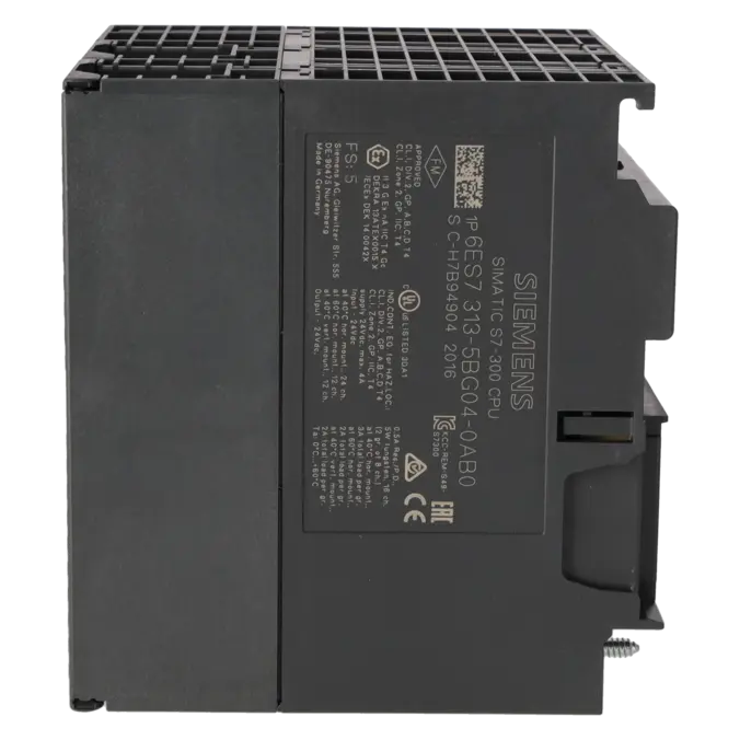
SIEMENS 6ES7313-5BG04-0AB0
-
SIEMENS | PLC Controls | Central Processing Units
- EICHLER-art.no.: K0252205
- EAN: 4025515079095
- UPC: 040892788563
Product description
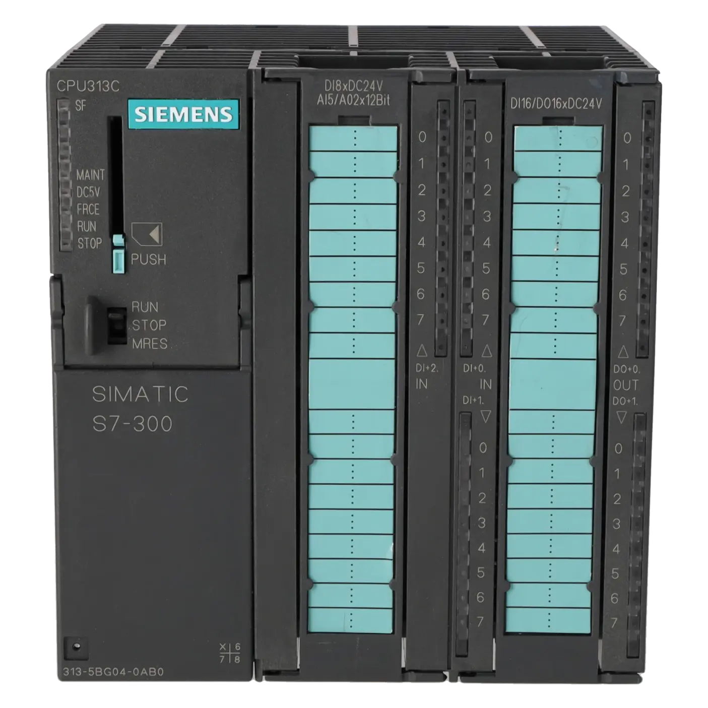
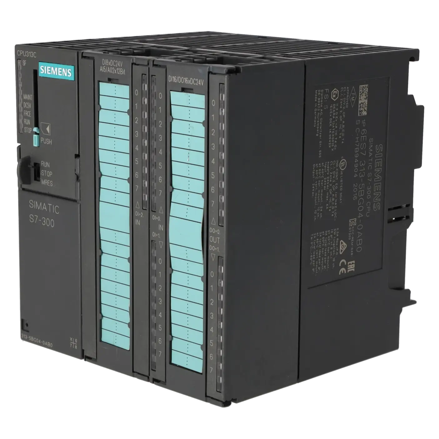
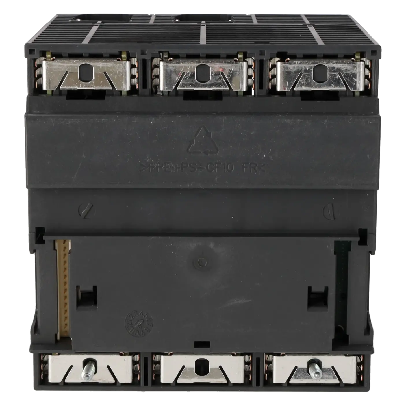
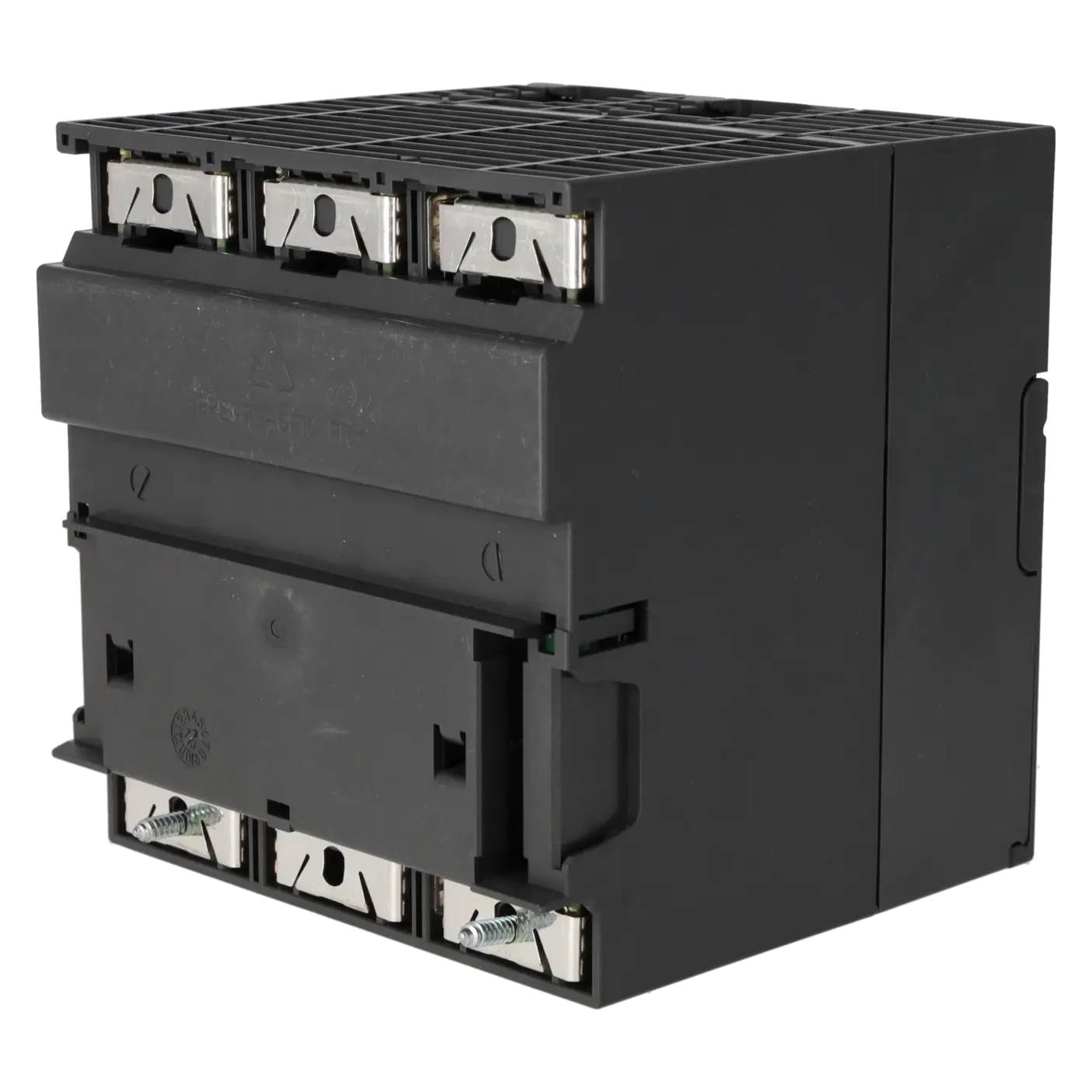
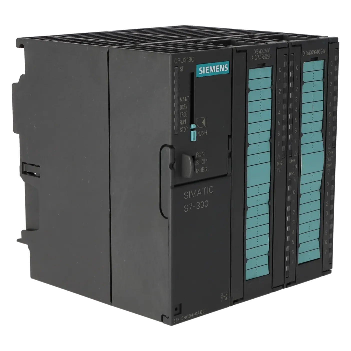
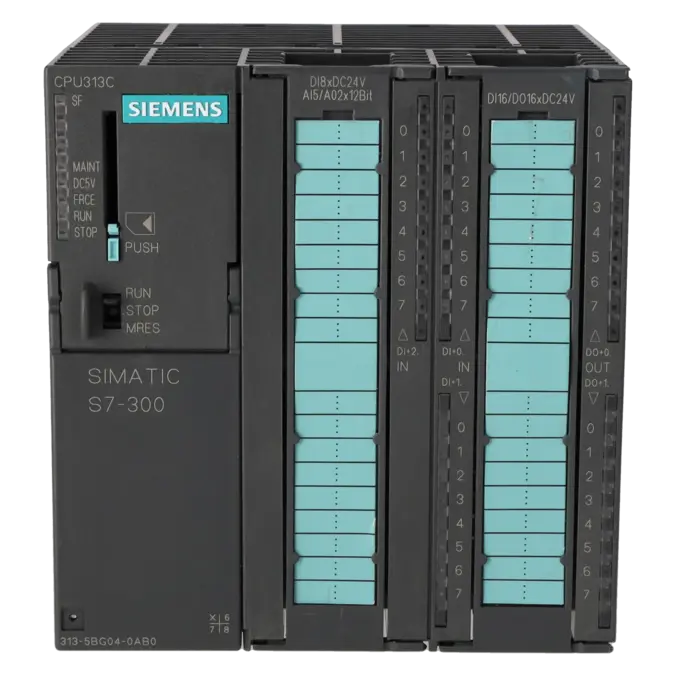
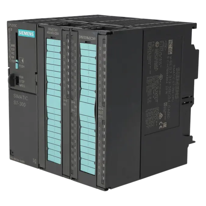
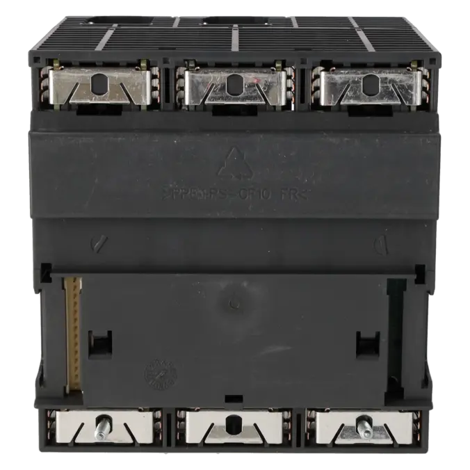
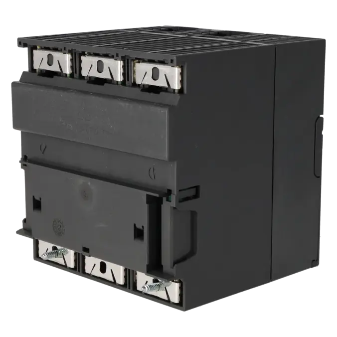
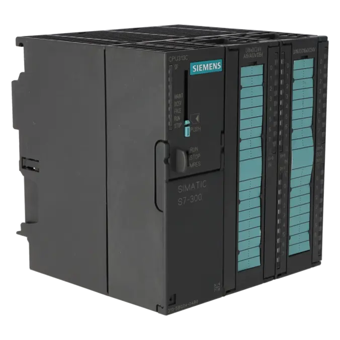
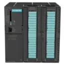
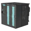
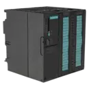
SIMATIC S7-300, CPU 313C, COMPACT CPU WITH MPI, 24 DI/16 DO, 4 AI, 2 AO, 1 PT100, 3 HIGH-SPEED COUNTERS (30 KHZ), INTEGR. POWER SUPPLY 24 V DC, WORK MEMORY 128 KB, FRONT CONNECTOR (2X 40-POLE) AND MICRO MEMORY CARD REQUIRED
Services for SIEMENS 6ES7313-5BG04-0AB0
Repair
from 715,04 €
to 1.287,08 €
Replacement
1.364,12 €
1.023,09 €
Used
1.515,69 €
1.136,77 €
New
1.684,10 €
1.263,07 €
SIEMENS |
6ES7313-5BG04-0AB0 –
additional product information
| Delivery information | |||
|---|---|---|---|
| Export identifier | AL: N ECCN: EAR99H | ||
| Net weight | 0.71 | ||
| Quantity | 1 Stück | ||
| Packaging quantity | 1 | ||
| Additional product information | |||
|---|---|---|---|
| Product status | EOP: 2025-10-01 | ||
| EAN | 4025515079095 | ||
| UPC | 040892788563 | ||
| Static lot number | 85371091 | ||
| List indicator | ST73 | ||
| Product group | 4256 | ||
| Country of origin | DE | ||
| Compliance with the substance restrictions according to RoHS directive | Since: 20110913 | ||
| Product classifications | Version | Classification | |
|---|---|---|---|
| eClass | 4 | / | |
| eClass | 5.1 | 27-24-22-07 | |
| eClass | 6.0 | 27-24-22-07 | |
| ETIM | 3 | / | |
| ETIM | 4 | EC000236 | |
| ETIM | 5 | EC000236 | |
What is the 6ES7313-5BG04-0AB0 and where is it used?
The SIEMENS 6ES7313-5BG04-0AB0 is a SIMATIC S7-300 CPU 313C in a compact design. It combines the controller function with integrated digital and analogue inputs and outputs within a single module. This makes it particularly suitable for compact machines, retrofit projects and clearly defined automation tasks. Typical applications include conveyor systems, assembly stations, packaging machines, test systems and smaller process sections with local I/O requirements. The CPU communicates via MPI, operates on 24 V DC, and requires a SIMATIC Micro Memory Card as well as two 40-pin front connectors. It is therefore especially attractive wherever existing S7-300 systems need to be maintained, replaced or economically secured with minimal effort.
Overview of the key technical data and what it means
The CPU provides 24 digital inputs, 16 digital outputs, 4 analogue inputs, 2 analogue outputs, 1 Pt100 channel and 3 high-speed counters up to 30 kHz. For many machine control applications, this is a major advantage because standard I/O and technological functions are already integrated without requiring additional base modules. The 128 KB work memory is designed for typical S7-300 applications using conventional STEP 7 engineering. Power is supplied via 24 V DC, with an allowable range of 19.2 to 28.8 V DC. The CPU has a typical current consumption of 650 mA and a typical power dissipation of 12 W. Siemens specifies STEP 7 V5.5 + SP1 or higher, or STEP 7 V5.3 + SP2 with HSP 203, for engineering. Another practical advantage is that the integrated channels use fixed standard address ranges, simplifying commissioning and replacement in existing installations.
Product status, life-cycle status and obsolescence
Siemens currently classifies the module as a spare part. According to the manufacturer information reviewed, an Announcement of Product Phase-Out was issued effective 01 October 2023, followed by Product Cancellation effective 01 October 2025. The EICHLER product page additionally lists the status as EOP: 2025-10-01. For maintenance, purchasing and production managers, this means that the CPU should be included in an active obsolescence management strategy, as long-term availability and spare-part supply may become increasingly limited. A clearly verified 1:1 plug-and-play successor for this exact MLFB could not be confirmed in the reviewed Siemens sources. For migration to the S7-1500 platform, Siemens identifies the CPU 1511C as a target CPU. However, this is a migration option, not a direct replacement without engineering effort.
Available EICHLER services and when they are relevant
For this CPU, EICHLER offers several practical options: repair, exchange, used and new units. Repair is particularly beneficial when the existing program, wiring and approvals should remain unchanged; EICHLER specifies typical turnaround times of 2 to 5 days. Exchange, used and new units are especially useful when unplanned downtime must be resolved quickly; the product page typically indicates 1 to 3 days for these options. An optional test report for CPUs/central processing units is also available, which is valuable for quality-critical systems and documentation requirements. Repair services include technical cleaning, preventive maintenance, comprehensive functional testing and a minimum 24-month warranty. This helps ensure continued operation of existing systems even when the CPU is already operating within an obsolescence environment.
| Attribute | Value |
|---|---|
| General information | |
| Product type designation | CPU 313C |
| HW functional status | 1 |
| Firmware version | V3.3 |
| Engineering with | |
| ● Programming package | STEP 7 V5.5 + SP1 or higher or STEP 7 V5.3 + SP2 or higher with HSP 203 |
| Supply voltage | |
| Rated value (DC) | 24 V |
| permissible range, lower limit (DC) | 19.2 V |
| permissible range, upper limit (DC) | 28.8 V |
| external protection for power supply lines (recommendation) | Miniature circuit breaker, type C; min. 2 A; miniature circuit breaker type B, min. 4 A |
| Mains buffering | |
| ● Mains/voltage failure stored energy time | 5 ms |
| ● Repeat rate, min. | 1 s |
| Load voltage L+ | |
| Digital inputs | |
| — Rated value (DC) | 24 V |
| — Reverse polarity protection | Yes |
| Digital outputs | |
| — Rated value (DC) | 24 V |
| — Reverse polarity protection | No |
| Input current | |
| Current consumption (rated value) | 650 mA |
| Current consumption (in no-load operation), typ. | 150 mA |
| Inrush current, typ. | 5 A |
| I²t | 0.7 A²·s |
| Digital inputs | |
| ● from load voltage L+ (without load), max. | 80 mA |
| Digital outputs | |
| ● from load voltage L+, max. | 50 mA |
| Power loss | |
| Power loss, typ. | 12 W |
| Memory | |
| Work memory | |
| ● integrated | 128 kbyte |
| ● expandable | No |
| Load memory | |
| ● Plug-in (MMC) | Yes |
| ● Plug-in (MMC), max. | 8 Mbyte |
| ● Data management on MMC (after last programming), min. | 10 a |
| Backup | |
| ● present | Yes; Guaranteed by MMC (maintenance-free) |
| ● without battery | Yes; Program and data |
| CPU processing times | |
| for bit operations, typ. | 0.07 µs |
| for word operations, typ. | 0.15 µs |
| for fixed point arithmetic, typ. | 0.2 µs |
| for floating point arithmetic, typ. | 0.72 µs |
| CPU-blocks | |
| Number of blocks (total) | 1 024; (DBs, FCs, FBs); the maximum number of loadable blocks can be reduced by the MMC used. |
| DB | |
| ● Number, max. | 1 024; Number range: 1 to 16000 |
| ● Size, max. | 64 kbyte |
| FB | |
| ● Number, max. | 1 024; Number range: 0 to 7999 |
| ● Size, max. | 64 kbyte |
| FC | |
| ● Number, max. | 1 024; Number range: 0 to 7999 |
| ● Size, max. | 64 kbyte |
| OB | |
| ● Number, max. | see instruction list |
| ● Size, max. | 64 kbyte |
| ● Number of free cycle OBs | 1; OB 1 |
| ● Number of time alarm OBs | 1; OB 10 |
| ● Number of delay alarm OBs | 2; OB 20, 21 |
| ● Number of cyclic interrupt OBs | 4; OB 32, 33, 34, 35 |
| ● Number of process alarm OBs | 1; OB 40 |
| ● Number of startup OBs | 1; OB 100 |
| ● Number of asynchronous error OBs | 4; OB 80, 82, 85, 87 |
| ● Number of synchronous error OBs | 2; OB 121, 122 |
| Nesting depth | |
| ● per priority class | 16 |
| ● additional within an error OB | 4 |
| Counters, timers and their retentivity | |
| S7 counter | |
| ● Number | 256 |
| Retentivity | |
| — adjustable | Yes |
| — preset | Z 0 to Z 7 |
| Counting range | |
| — lower limit | 0 |
| — upper limit | 999 |
| IEC counter | |
| ● present | Yes |
| ● Type | SFB |
| ● Number | Unlimited (limited only by RAM capacity) |
| S7 times | |
| ● Number | 256 |
| Retentivity | |
| — adjustable | Yes |
| — preset | No retentivity |
| Time range | |
| — lower limit | 10 ms |
| — upper limit | 9 990 s |
| IEC timer | |
| ● present | Yes |
| ● Type | SFB |
| ● Number | Unlimited (limited only by RAM capacity) |
| Data areas and their retentivity | |
| Retentive data area (incl. timers, counters, flags), max. | 64 kbyte |
| Flag | |
| ● Size, max. | 256 byte |
| ● Retentivity available | Yes; MB 0 to MB 255 |
| ● Retentivity preset | MB 0 to MB 15 |
| ● Number of clock memories | 8; 1 memory byte |
| Data blocks | |
| ● Retentivity adjustable | Yes; via non-retain property on DB |
| ● Retentivity preset | Yes |
| Local data | |
| ● per priority class, max. | 32 kbyte; Max. 2048 bytes per block |
| Address area | |
| I/O address area | |
| ● Inputs | 1 024 byte |
| ● Outputs | 1 024 byte |
| of which distributed | |
| — Inputs | none |
| — Outputs | none |
| Process image | |
| ● Inputs | 1 024 byte |
| ● Outputs | 1 024 byte |
| ● Inputs, adjustable | 1 024 byte |
| ● Outputs, adjustable | 1 024 byte |
| ● Inputs, default | 128 byte |
| ● Outputs, default | 128 byte |
| Digital channels | |
| ● Inputs | 1 016 |
| — of which central | 1 016 |
| ● Outputs | 1 008 |
| — of which central | 1 008 |
| Analog channels | |
| ● Inputs | 253 |
| — of which central | 253 |
| ● Outputs | 250 |
| — of which central | 250 |
| Hardware configuration | |
| Number of expansion units, max. | 3 |
| Number of DP masters | |
| ● integrated | none |
| ● via CP | 4 |
| Number of operable FMs and CPs (recommended) | |
| ● FM | 8 |
| ● CP, PtP | 8 |
| ● CP, LAN | 6 |
| Rack | |
| ● Racks, max. | 4 |
| ● Modules per rack, max. | 8; In rack 3 max. 7 |
| Time of day | |
| Clock | |
| ● Hardware clock (real-time) | Yes |
| ● retentive and synchronizable | Yes |
| ● Backup time | 6 wk; At 40 °C ambient temperature |
| ● Deviation per day, max. | 10 s; Typ.: 2 s |
| ● Behavior of the clock following POWER-ON | Clock continues running after POWER OFF |
| ● Behavior of the clock following expiry of backup period | the clock continues at the time of day it had when power was switched off |
| Operating hours counter | |
| ● Number | 1 |
| ● Number/Number range | 0 |
| ● Range of values | 0 to 2^31 hours (when using SFC 101) |
| ● Granularity | 1 h |
| ● retentive | Yes; Must be restarted at each restart |
| Clock synchronization | |
| ● supported | Yes |
| ● to MPI, master | Yes |
| ● on MPI, device | Yes |
| ● in AS, master | Yes |
| ● in AS, device | No |
| Digital inputs | |
| Number of digital inputs | 24 |
| ● of which inputs usable for technological functions | 12 |
| integrated channels (DI) | 24 |
| Input characteristic curve in accordance with IEC 61131, type 1 | Yes |
| Number of simultaneously controllable inputs | |
| horizontal installation | |
| — up to 40 °C, max. | 24 |
| — up to 60 °C, max. | 12 |
| vertical installation | |
| — up to 40 °C, max. | 12 |
| Input voltage | |
| ● Rated value (DC) | 24 V |
| ● for signal "0" | -3 to +5V |
| ● for signal "1" | +15 to +30 V |
| Input current | |
| ● for signal "1", typ. | 8 mA |
| Input delay (for rated value of input voltage) | |
| for standard inputs | |
| — parameterizable | Yes; 0.1 / 0.3 / 3 / 15 ms (You can reconfigure the input delay of the standard inputs during program runtime. Please note that under certain circumstances your newly set filter time may not be effective until the next filter cycle.) |
| — Rated value | 3 ms |
| for technological functions | |
| — at "0" to "1", max. | 16 µs; Minimum pulse width/minimum pause between pulses at maximum counting frequency |
| Cable length | |
| ● shielded, max. | 1 000 m; 100 m for technological functions |
| ● unshielded, max. | 600 m; for technological functions: No |
| for technological functions | |
| — shielded, max. | 100 m; at maximum count frequency |
| — unshielded, max. | not allowed |
| Digital outputs | |
| Number of digital outputs | 16 |
| ● of which high-speed outputs | 4; Notice: You cannot connect the fast outputs of your CPU in parallel |
| integrated channels (DO) | 16 |
| Short-circuit protection | Yes; Clocked electronically |
| ● Response threshold, typ. | 1 A |
| Limitation of inductive shutdown voltage to | L+ (-48 V) |
| Controlling a digital input | Yes |
| Switching capacity of the outputs | |
| ● on lamp load, max. | 5 W |
| Load resistance range | |
| ● lower limit | 48 Ω |
| ● upper limit | 4 kΩ |
| Output voltage | |
| ● for signal "1", min. | L+ (-0.8 V) |
| Output current | |
| ● for signal "1" rated value | 500 mA |
| ● for signal "1" permissible range, min. | 5 mA |
| ● for signal "1" permissible range, max. | 0.6 A |
| ● for signal "1" minimum load current | 5 mA |
| ● for signal "0" residual current, max. | 0.5 mA |
| Parallel switching of two outputs | |
| ● for uprating | No |
| ● for redundant control of a load | Yes |
| Switching frequency | |
| ● with resistive load, max. | 100 Hz |
| ● with inductive load, max. | 0.5 Hz |
| ● on lamp load, max. | 100 Hz |
| ● of the pulse outputs, with resistive load, max. | 2.5 kHz |
| Total current of the outputs (per group) | |
| horizontal installation | |
| — up to 40 °C, max. | 3 A |
| — up to 60 °C, max. | 2 A |
| vertical installation | |
| — up to 40 °C, max. | 2 A |
| Cable length | |
| ● shielded, max. | 1 000 m |
| ● unshielded, max. | 600 m |
| Analog inputs | |
| Number of analog inputs | 4 |
| ● For voltage/current measurement | 4 |
| ● For resistance/resistance thermometer measurement | 1 |
| integrated channels (AI) | 5; 4x current/voltage, 1x resistance |
| permissible input voltage for current input (destruction limit), max. | 5 V; Permanent |
| permissible input voltage for voltage input (destruction limit), max. | 30 V; Permanent |
| permissible input current for voltage input (destruction limit), max. | 0.5 mA; Permanent |
| permissible input current for current input (destruction limit), max. | 50 mA; Permanent |
| Electrical input frequency, max. | 400 Hz |
| No-load voltage for resistance-type transmitter, typ. | 3.3 V |
| Constant measurement current for resistance-type transmitter, typ. | 1.25 mA |
| Technical unit for temperature measurement adjustable | Yes; Degrees Celsius / degrees Fahrenheit / Kelvin |
| Input ranges | |
| ● Voltage | Yes; ±10 V / 100 kΩ; 0 V to 10 V / 100 kΩ |
| ● Current | Yes; ±20 mA / 100 Ω; 0 mA to 20 mA / 100 Ω; 4 mA to 20 mA / 100 Ω |
| ● Resistance thermometer | Yes; Pt 100 / 10 MΩ |
| ● Resistance | Yes; 0 Ω to 600 Ω / 10 MΩ |
| Input ranges (rated values), voltages | |
| ● 0 to +10 V | Yes |
| — Input resistance (0 to 10 V) | 100 kΩ |
| Input ranges (rated values), currents | |
| ● 0 to 20 mA | Yes |
| — Input resistance (0 to 20 mA) | 100 Ω |
| ● -20 mA to +20 mA | Yes |
| — Input resistance (-20 mA to +20 mA) | 100 Ω |
| ● 4 mA to 20 mA | Yes |
| — Input resistance (4 mA to 20 mA) | 100 Ω |
| Input ranges (rated values), resistance thermometer | |
| ● Pt 100 | Yes |
| — Input resistance (Pt 100) | 10 MΩ |
| Input ranges (rated values), resistors | |
| ● 0 to 600 ohms | Yes |
| — Input resistance (0 to 600 ohms) | 10 MΩ |
| Thermocouple (TC) | |
| Temperature compensation | |
| — parameterizable | No |
| Characteristic linearization | |
| ● parameterizable | Yes; by software |
| — for resistance thermometer | Pt 100 |
| Cable length | |
| ● shielded, max. | 100 m |
| Analog outputs | |
| integrated channels (AO) | 2 |
| Voltage output, short-circuit protection | Yes |
| Voltage output, short-circuit current, max. | 55 mA |
| Current output, no-load voltage, max. | 14 V |
| Output ranges, voltage | |
| ● 0 to 10 V | Yes |
| ● -10 V to +10 V | Yes |
| Output ranges, current | |
| ● 0 to 20 mA | Yes |
| ● -20 mA to +20 mA | Yes |
| ● 4 mA to 20 mA | Yes |
| Connection of actuators | |
| ● for voltage output two-wire connection | Yes; Without compensation of the line resistances |
| ● for voltage output four-wire connection | No |
| ● for current output two-wire connection | Yes |
| Load impedance (in rated range of output) | |
| ● with voltage outputs, min. | 1 kΩ |
| ● with voltage outputs, capacitive load, max. | 0.1 µF |
| ● with current outputs, max. | 300 Ω |
| ● with current outputs, inductive load, max. | 0.1 mH |
| Destruction limits against externally applied voltages and currents | |
| ● Voltages at the outputs towards MANA | 16 V; Permanent |
| ● Current, max. | 50 mA; Permanent |
| Cable length | |
| ● shielded, max. | 200 m |
| Analog value generation for the inputs | |
| Measurement principle | Actual value encryption (successive approximation) |
| Integration and conversion time/resolution per channel | |
| ● Resolution with overrange (bit including sign), max. | 12 bit |
| ● Integration time, parameterizable | Yes; 16.6 / 20 ms |
| ● Interference voltage suppression for interference frequency f1 in Hz | 50 / 60 Hz |
| ● Time constant of the input filter | 0.38 ms |
| ● Basic execution time of the module (all channels released) | 1 ms |
| Analog value generation for the outputs | |
| Integration and conversion time/resolution per channel | |
| ● Resolution with overrange (bit including sign), max. | 12 bit |
| ● Conversion time (per channel) | 1 ms |
| Settling time | |
| ● for resistive load | 0.6 ms |
| ● for capacitive load | 1 ms |
| ● for inductive load | 0.5 ms |
| Encoder | |
| Connection of signal encoders | |
| ● for voltage measurement | Yes |
| ● for current measurement as 2-wire transducer | Yes; with external supply |
| ● for current measurement as 4-wire transducer | Yes |
| ● for resistance measurement with two-wire connection | Yes; Without compensation of the line resistances |
| ● for resistance measurement with three-wire connection | No |
| ● for resistance measurement with four-wire connection | No |
| Connectable encoders | |
| ● 2-wire sensor | Yes |
| — permissible quiescent current (2-wire sensor), max. | 1.5 mA |
| Errors/accuracies | |
| Temperature error (relative to input range), (+/-) | 0.006 %/K |
| Crosstalk between the inputs, min. | 60 dB |
| Repeat accuracy in steady state at 25 °C (relative to input range), (+/-) | 0.06 % |
| Output ripple (relative to output range, bandwidth 0 to 50 kHz), (+/-) | 0.1 % |
| Linearity error (relative to output range), (+/-) | 0.15 % |
| Temperature error (relative to output range), (+/-) | 0.01 %/K |
| Crosstalk between the outputs, min. | 60 dB |
| Repeat accuracy in steady state at 25 °C (relative to output range), (+/-) | 0.06 % |
| Operational error limit in overall temperature range | |
| ● Voltage, relative to input range, (+/-) | 1 % |
| ● Current, relative to input range, (+/-) | 1 % |
| ● Resistance, relative to input range, (+/-) | 1 % |
| ● Voltage, relative to output range, (+/-) | 1 % |
| ● Current, relative to output range, (+/-) | 1 % |
| Basic error limit (operational limit at 25 °C) | |
| ● Voltage, relative to input range, (+/-) | 0.8 %; Linearity error ±0.06 % |
| ● Current, relative to input range, (+/-) | 0.8 %; Linearity error ±0.06 % |
| ● Resistance, relative to input range, (+/-) | 0.8 %; Linearity error ±0.2 % |
| ● Resistance thermometer, relative to input range, (+/-) | 0.8 % |
| ● Voltage, relative to output range, (+/-) | 0.8 % |
| ● Current, relative to output range, (+/-) | 0.8 % |
| Interference voltage suppression for f = n x (f1 +/- 1 %), f1 = interference frequency | |
| ● Series mode interference (peak value of interference < rated value of input range), min. | 30 dB |
| ● Common mode interference, min. | 40 dB |
| Interfaces | |
| Number of PROFINET interfaces | 0 |
| Number of RS 485 interfaces | 1; MPI |
| Number of RS 422 interfaces | 0 |
| 1. Interface | |
| Interface type | Integrated RS 485 interface |
| Isolated | No |
| Interface types | |
| ● RS 485 | Yes |
| ● Output current of the interface, max. | 200 mA |
| Protocols | |
| ● MPI | Yes |
| ● PROFIBUS DP master | No |
| ● PROFIBUS DP device | No |
| ● Point-to-point connection | No |
| MPI | |
| ● Transmission rate, max. | 187.5 kbit/s |
| Services | |
| — PG/OP communication | Yes |
| — Routing | No |
| — Global data communication | Yes |
| — S7 basic communication | Yes |
| — S7 communication | Yes; Only server, configured on one side |
| — S7 communication, as client | No; but via CP and loadable FB |
| — S7 communication, as server | Yes |
| Protocols | |
| PROFIsafe | No |
| Communication functions | |
| PG/OP communication | Yes |
| Data record routing | No |
| Global data communication | |
| ● supported | Yes |
| ● Number of GD loops, max. | 8 |
| ● Number of GD packets, max. | 8 |
| ● Number of GD packets, transmitter, max. | 8 |
| ● Number of GD packets, receiver, max. | 8 |
| ● Size of GD packets, max. | 22 byte |
| ● Size of GD packet (of which consistent), max. | 22 byte |
| S7 basic communication | |
| ● supported | Yes |
| ● User data per job, max. | 76 byte |
| ● User data per job (of which consistent), max. | 76 byte; 76 bytes (with X_SEND or X_RCV); 64 bytes (with X_PUT or X_GET as server) |
| S7 communication | |
| ● supported | Yes |
| ● as server | Yes |
| ● as client | Yes; Via CP and loadable FB |
| ● User data per job, max. | 180 byte; With PUT/GET |
| ● User data per job (of which consistent), max. | 240 byte; as server |
| S5 compatible communication | |
| ● supported | Yes; via CP and loadable FC |
| Number of connections | |
| ● overall | 8 |
| ● usable for PG communication | 7 |
| — reserved for PG communication | 1 |
| — adjustable for PG communication, min. | 1 |
| — adjustable for PG communication, max. | 7 |
| ● usable for OP communication | 7 |
| — reserved for OP communication | 1 |
| — adjustable for OP communication, min. | 1 |
| — adjustable for OP communication, max. | 7 |
| ● usable for S7 basic communication | 4 |
| — reserved for S7 basic communication | 0 |
| — adjustable for S7 basic communication, min. | 0 |
| — adjustable for S7 basic communication, max. | 4 |
| S7 message functions | |
| Number of login stations for message functions, max. | 8; Depending on the configured connections for PG/OP and S7 basic communication |
| Process diagnostic messages | Yes |
| simultaneously active Alarm_S blocks, max. | 300 |
| Test commissioning functions | |
| Status block | Yes; Up to 2 simultaneously |
| Single step | Yes |
| Number of breakpoints | 4 |
| Status/control | |
| ● Status/control variable | Yes |
| ● Variables | Inputs, outputs, memory bits, DB, times, counters |
| ● Number of variables, max. | 30 |
| — of which status variables, max. | 30 |
| — of which control variables, max. | 14 |
| Forcing | |
| ● Forcing | Yes |
| ● Forcing, variables | Inputs, outputs |
| ● Number of variables, max. | 10 |
| Diagnostic buffer | |
| ● present | Yes |
| ● Number of entries, max. | 500 |
| — adjustable | No |
| — of which powerfail-proof | 100; Only the last 100 entries are retained |
| ● Number of entries readable in RUN, max. | 499 |
| — adjustable | Yes; From 10 to 499 |
| — preset | 10 |
| Service data | |
| ● can be read out | Yes |
| Interrupts/diagnostics/status information | |
| Diagnostics indication LED | |
| ● Status indicator digital input (green) | Yes |
| ● Status indicator digital output (green) | Yes |
| Integrated Functions | |
| Counter | |
| ● Number of counters | 3; See "Technological Functions" manual |
| ● Counting frequency, max. | 30 kHz |
| Frequency measurement | Yes |
| ● Number of frequency meters | 3; up to 30 kHz (see "Technological Functions" manual) |
| controlled positioning | No |
| integrated function blocks (closed-loop control) | Yes; PID controller (see "Technological Functions" manual) |
| PID controller | Yes |
| Number of pulse outputs | 3; Pulse width modulation up to 2.5 kHz (see "Technological Functions" Manual) |
| Limit frequency (pulse) | 2.5 kHz |
| Potential separation | |
| Potential separation digital inputs | |
| ● Potential separation digital inputs | Yes |
| ● between the channels | No |
| ● between the channels and backplane bus | Yes |
| Potential separation digital outputs | |
| ● Potential separation digital outputs | Yes |
| ● between the channels | Yes |
| ● between the channels, in groups of | 8 |
| ● between the channels and backplane bus | Yes |
| Potential separation analog inputs | |
| ● Potential separation analog inputs | Yes; common for analog I/O |
| ● between the channels | No |
| ● between the channels and backplane bus | Yes |
| Potential separation analog outputs | |
| ● Potential separation analog outputs | Yes; common for analog I/O |
| ● between the channels | No |
| ● between the channels and backplane bus | Yes |
| Isolation | |
| Isolation tested with | 600 V DC |
| Ambient conditions | |
| Ambient temperature during operation | |
| ● min. | 0 °C |
| ● max. | 60 °C |
| Configuration | |
| Configuration software | |
| ● STEP 7 | Yes; STEP 7 V5.5 + SP1 or higher or STEP 7 V5.3 + SP2 or higher with HSP 203 |
| ● STEP 7 Lite | No |
| Programming | |
| ● Command set | see instruction list |
| ● Nesting levels | 8 |
| ● System functions (SFC) | see instruction list |
| ● System function blocks (SFB) | see instruction list |
| Programming language | |
| — LAD | Yes |
| — FBD | Yes |
| — STL | Yes |
| — SCL | Yes |
| — CFC | Yes |
| — GRAPH | Yes |
| — HiGraph® | Yes |
| Know-how protection | |
| ● User program protection/password protection | Yes |
| ● Block encryption | Yes; With S7 block Privacy |
| Dimensions | |
| Width | 120 mm |
| Height | 125 mm |
| Depth | 130 mm |
| Weights | |
| Weight, approx. | 660 g |
| Fault description | Possible solution |
|---|---|
| Why does my CPU 313C go into STOP with an SF fault even though I only changed the program? | In many cases, the cause is a programming error, such as a block that was not downloaded, an incorrect block number, an invalid timer or counter access, or an access to an incorrect memory area. Siemens specifies that OB121 is called in these situations. If OB121 is not loaded, the CPU enters STOP mode. Therefore, first read the diagnostic buffer, then check the affected block calls, DB accesses and absolute addresses in STEP 7, and finally recompile and download the corrected project completely. |
| Why does the CPU 313C go into STOP due to a peripheral access error or module fault? | If an error occurs while reading from or writing to a module, Siemens states that OB122 is called. If OB122 is not present, the CPU enters STOP mode. Check the addressing in the hardware configuration, the actual slot assignment, the wiring and the condition of the affected modules, DP slaves or IO devices. Loose connectors or defective modules should be secured or replaced. Afterwards, check the diagnostic buffer and the process image again. |
| Why do the BF and SF LEDs light up after a PROFIBUS DP slave failure? | Depending on the cause, Siemens assigns this condition to OB86 or OB82. If these OBs are not available, the CPU may enter STOP mode. If they are present, the CPU will often remain operational or be able to restart even though BF and SF remain active. To ensure a controlled response, station failures and diagnostic alarms should be handled within the user program. In addition, check the bus connectors, terminating resistors, slave power supply and the parameterisation of the affected DP device. |
| Why does the CPU not start after replacing the MMC, or why does the STOP LED flash continuously? | The CPU 313C requires a SIMATIC Micro Memory Card (MMC). If the MMC is defective, incorrectly programmed or contains a project or hardware configuration that does not match the actual station, the CPU may remain in STOP mode or request a complete memory reset. Siemens also notes that users should not format the MMC in the conventional sense, but only reset it. In practice, this means using a suitable MMC, correctly resetting both the CPU and the MMC, downloading the project again and only then switching the CPU back to RUN. |
Is the 6ES7313-5BG04-0AB0 still available or has it been discontinued?
The CPU is no longer a standard growth product. Siemens classifies it as a spare part and specifies an Announcement of Product Phase-Out effective 01 October 2023 as well as a Product Cancellation effective 01 October 2025. At the same time, the EICHLER product page shows that several procurement and service options remain available for this CPU, including repair, exchange, used and new units. For purchasing and maintenance departments, this means that the CPU is still available, but it should no longer be treated as a long-term low-risk catalogue item. Availability, response time and supply security should be actively managed.
Which memory card does the 6ES7313-5BG04-0AB0 require?
The CPU requires a SIMATIC Micro Memory Card (MMC). Siemens explicitly states that these CPUs do not have an integrated load memory and therefore cannot operate without an MMC installed. The datasheet also specifies a pluggable load memory of up to 8 MB. For operators, it is important that the card is not only compatible with the CPU but also provides sufficient capacity for project and application data. When troubleshooting issues related to card replacement, project transfer or memory reset procedures, the MMC should always be one of the first items checked.
Which software can be used to configure the CPU?
Siemens specifies STEP 7 V5.5 + SP1 or higher, or STEP 7 V5.3 + SP2 with HSP 203, for engineering this CPU. In addition, Siemens notes in the firmware documentation that TIA Portal V12 or later should be used where possible. For existing installations, this confirms that the CPU is strongly rooted in the classic STEP 7 environment, while still being supported in many modern engineering environments. Before making changes to critical systems, the project version, hardware catalogue and firmware version should always be checked for consistency.
Can I simply replace a defective CPU 313C with the same part number?
Replacing the unit with the same MLFB 6ES7313-5BG04-0AB0 minimises the amount of modification required because the basic functionality and integrated I/O structure remain unchanged. Before returning the system to operation, however, the MMC contents, hardware configuration, addressing, firmware version and diagnostic buffer should be checked. In older systems, problems are often caused not by the CPU itself but by incompatible memory card contents, inconsistent project versions or peripheral deviations. In practice, a 1:1 replacement is usually the safest approach, provided that the project, memory card and connected peripherals have been verified beforehand.
Is there a direct successor or only a migration option?
For this exact part number, no clearly verified 1:1-compatible direct successor could be confirmed in the reviewed Siemens documentation. In the S7-300/S7-400 to S7-1500 migration guide, Siemens identifies the CPU 1511C as the target CPU for modernisation projects. This is important for decision-makers because the 1511C represents a documented migration path, but not a plug-compatible replacement without engineering effort, hardware verification and migration planning. For short-term availability, the combination of repair, exchange or sourcing an identical replacement CPU is generally the lower-risk option.
When is repair more economical than used, exchange or new equipment?
Repair is particularly cost-effective when the system must be returned to operation quickly and the existing program, wiring and approval status should remain unchanged. Exchange units are advantageous when downtime is the critical factor and a fully tested replacement is required immediately. Used units can be attractive when availability and budget are the primary concerns. New units are often preferred by organisations that require the clearest possible material history and traceability. At EICHLER, the decision is further supported by short response times, optional test reports and a minimum 24-month warranty on repairs, helping operators balance cost, risk and long-term availability.