| General information |
|
| Product type designation |
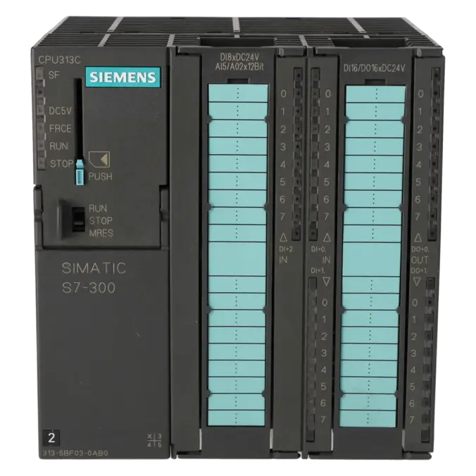
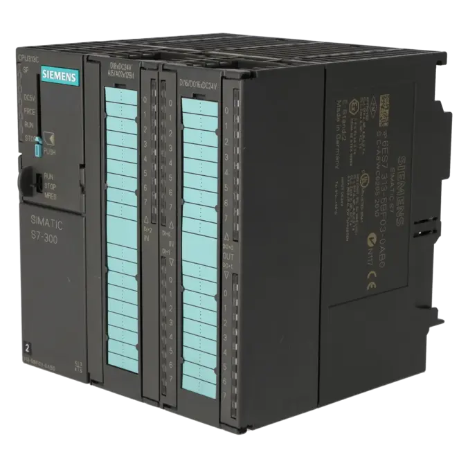
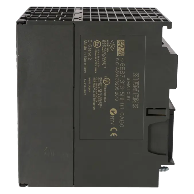
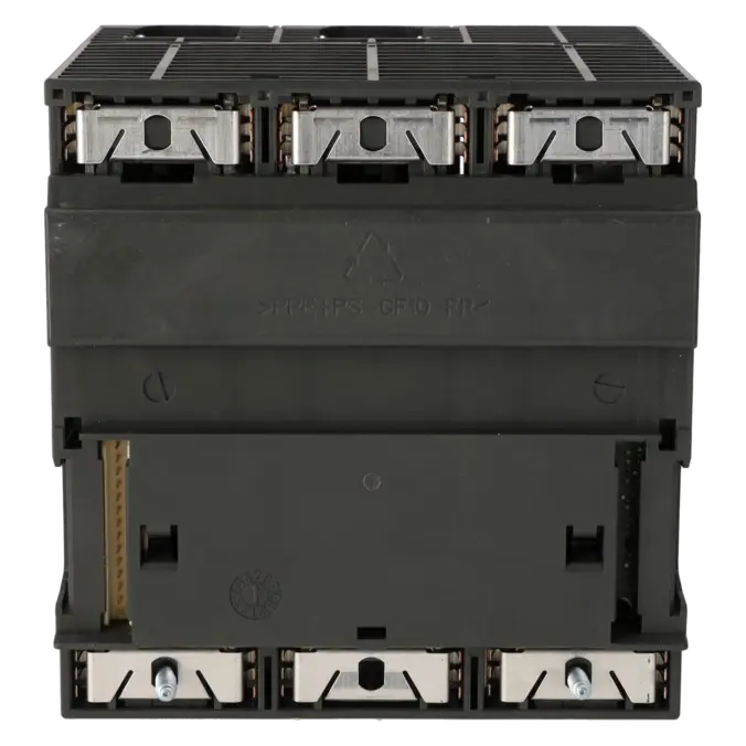
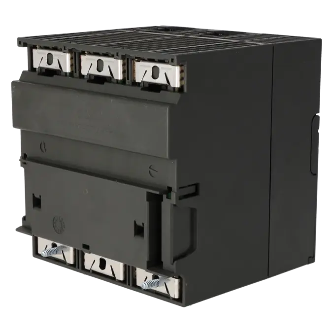
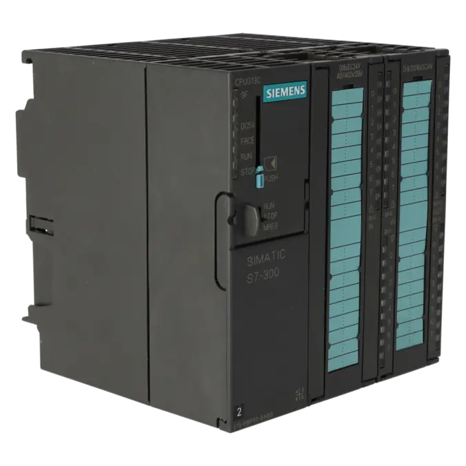
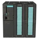
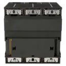
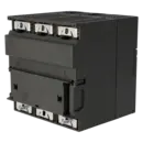
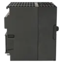
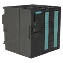
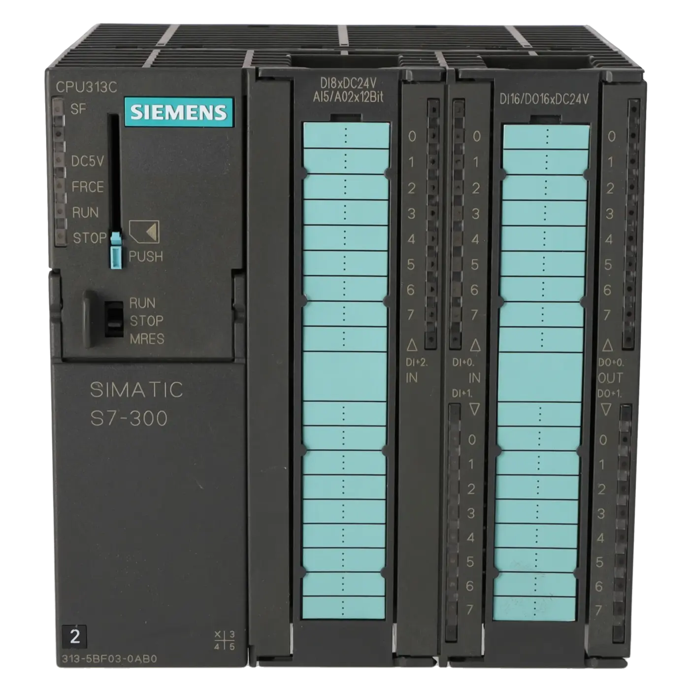
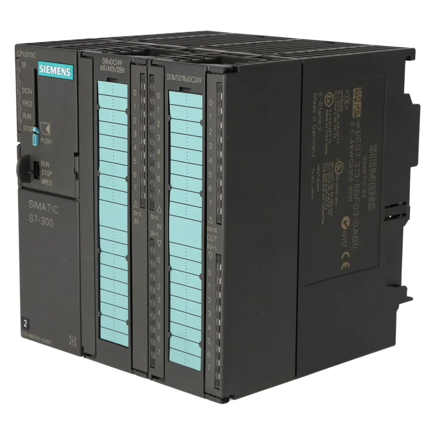
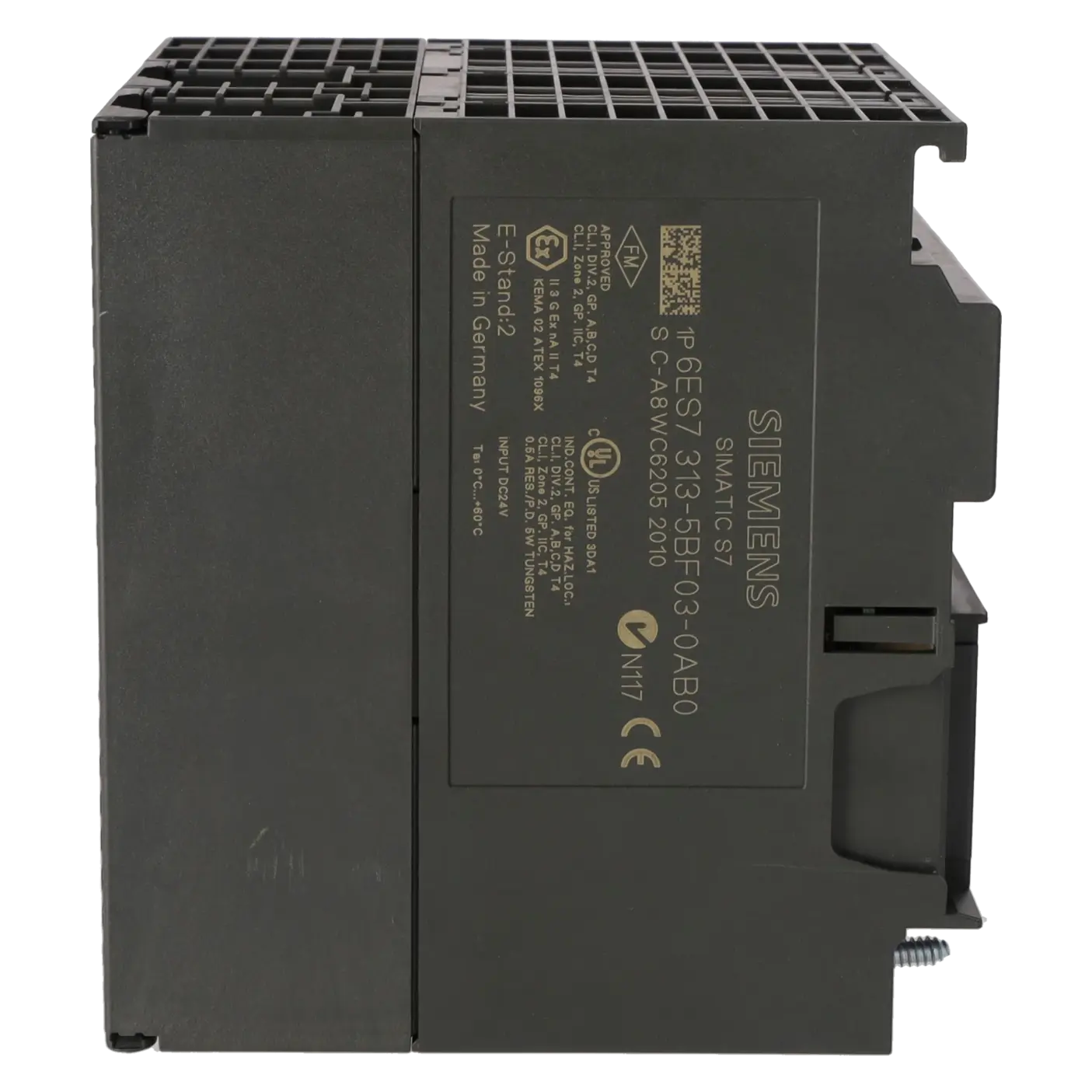
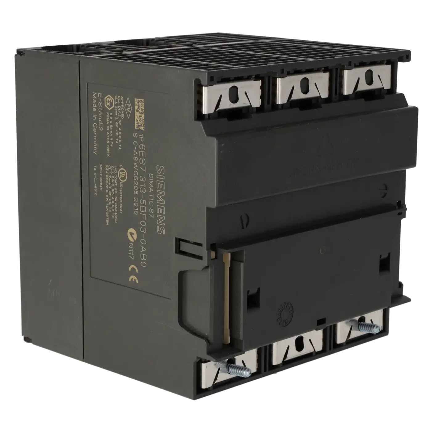
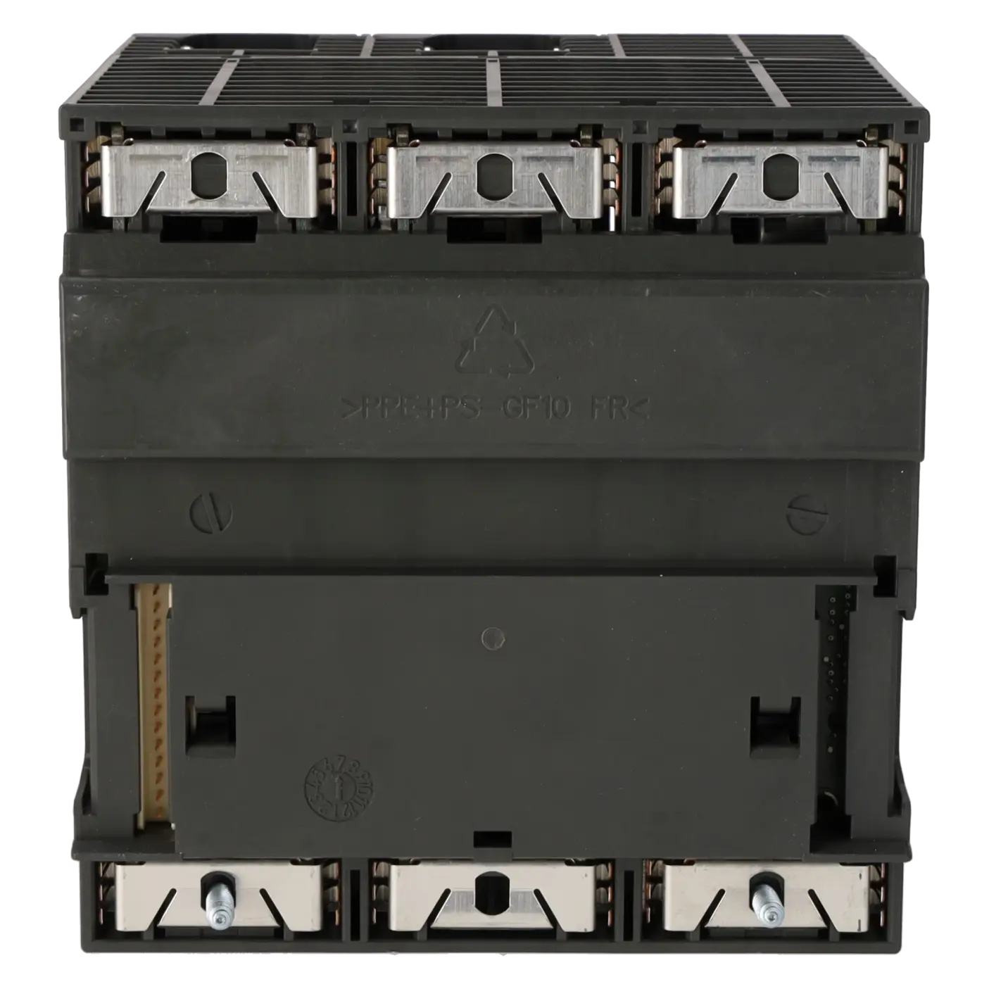
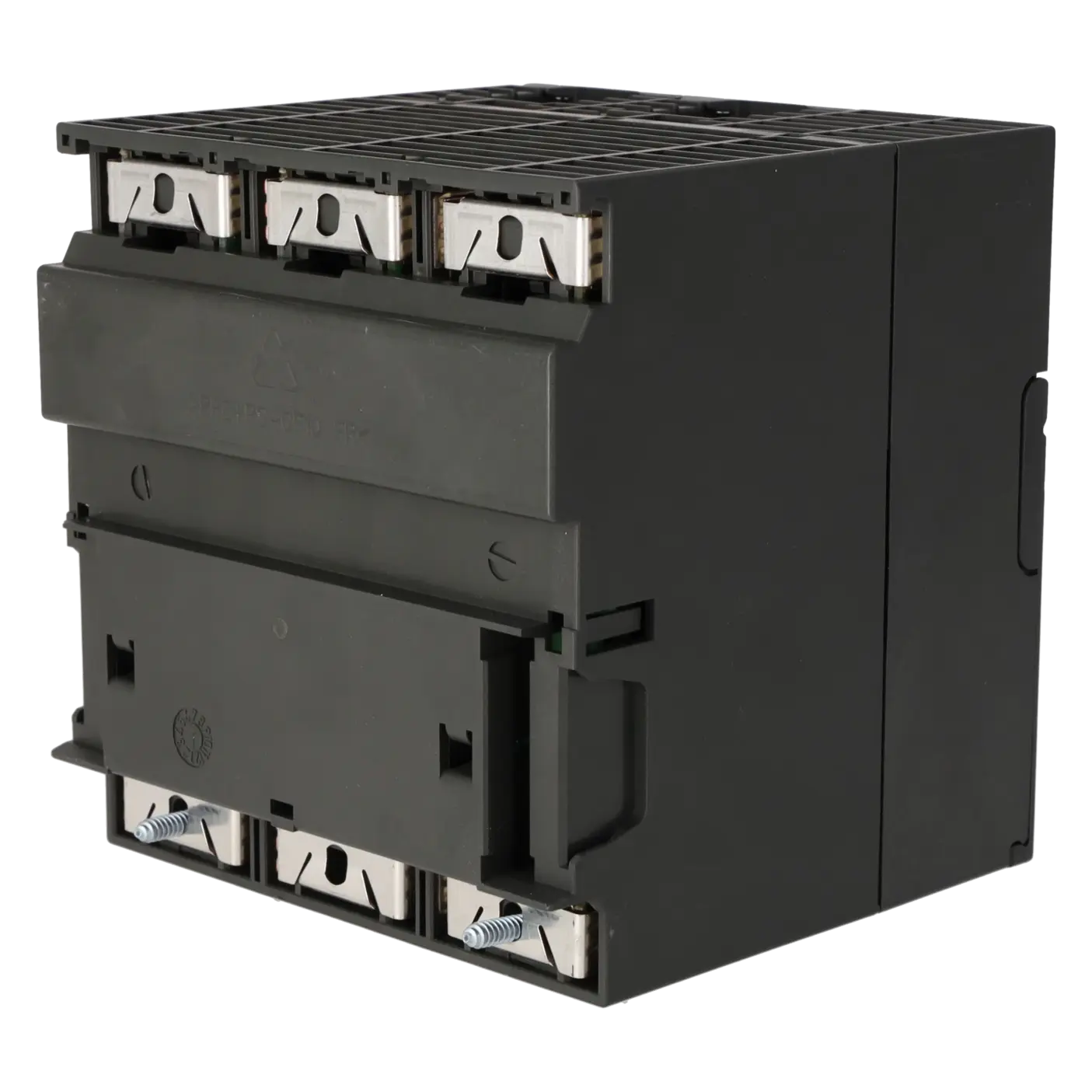
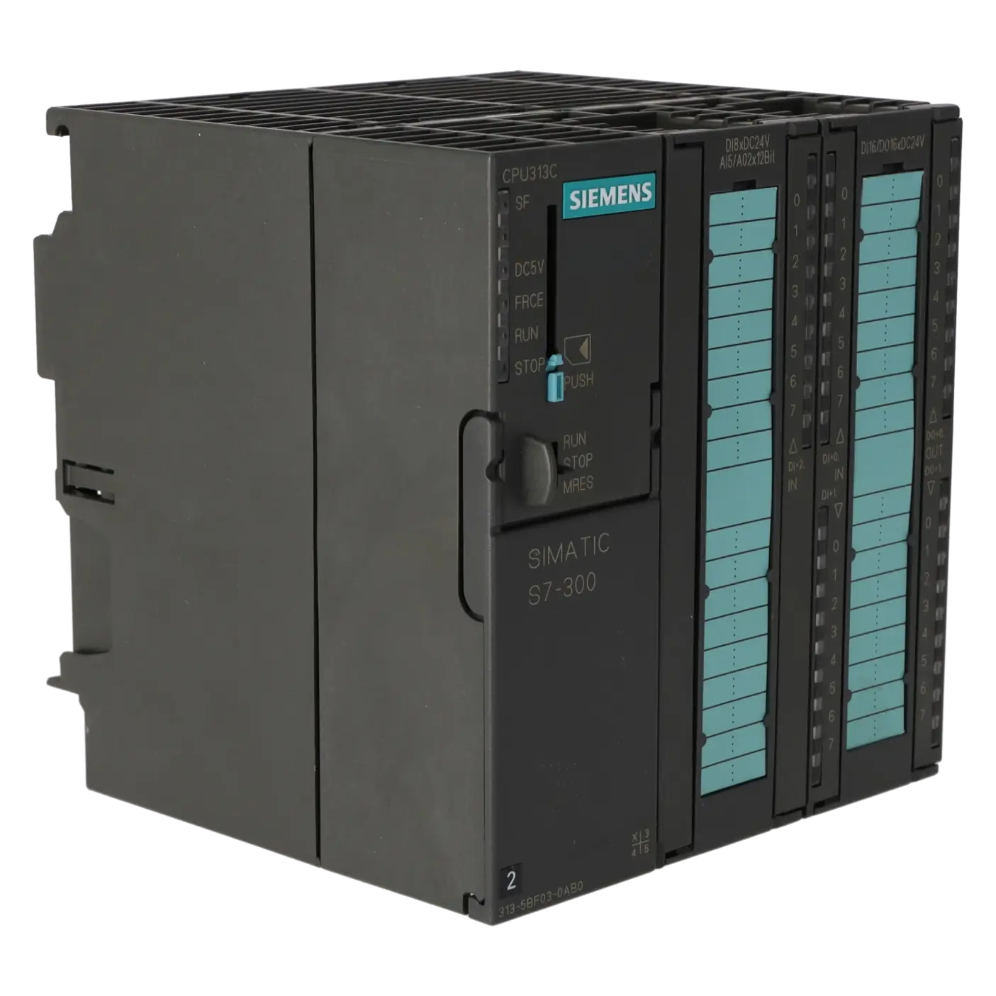
CPU 313C |
| HW functional status |
1 |
| Firmware version |
V2.6 |
| Engineering with |
|
| ● Programming package |
STEP 7 V5.3 SP2 or higher with HW update |
| Supply voltage |
|
| Rated value (DC) |
24 V |
| permissible range, lower limit (DC) |
20.4 V |
| permissible range, upper limit (DC) |
28.8 V |
| external protection for power supply lines (recommendation) |
Miniature circuit breaker, type C; min. 2 A; miniature circuit breaker type B, min. 4 A |
| Load voltage L+ |
|
| ● Rated value (DC) |
24 V |
| ● permissible range, lower limit (DC) |
20.4 V |
| ● permissible range, upper limit (DC) |
28.8 V |
| Digital inputs |
|
| — load voltage / at digital input / at DC / rated value |
24 V |
| — Reverse polarity protection |
Yes |
| Digital outputs |
|
| — Rated value (DC) |
24 V |
| — Reverse polarity protection |
No |
| Analog outputs |
|
| — load voltage / at analog output / at DC / rated value |
24 V |
| — Reverse polarity protection |
Yes |
| Input current |
|
| Current consumption (rated value) |
700 mA |
| Current consumption (in no-load operation), typ. |
150 mA |
| Inrush current, typ. |
11 A |
| I²t |
0.7 A²·s |
| Digital inputs |
|
| ● from load voltage L+ (without load), max. |
70 mA |
| Digital outputs |
|
| ● from load voltage L+, max. |
100 mA |
| Power loss |
|
| Power loss, typ. |
14 W |
| Memory |
|
| Work memory |
|
| ● integrated |
64 kbyte |
| ● expandable |
No |
| Load memory |
|
| ● Plug-in (MMC) |
Yes |
| ● Plug-in (MMC), max. |
8 Mbyte |
| ● Data management on MMC (after last programming), min. |
10 a |
| Backup |
|
| ● present |
Yes; Guaranteed by MMC (maintenance-free) |
| ● without battery |
Yes; Program and data |
| CPU processing times |
|
| for bit operations, typ. |
0.1 µs |
| for bit operations, max. |
0.2 µs |
| for word operations, typ. |
0.2 µs |
| for fixed point arithmetic, typ. |
2 µs |
| for floating point arithmetic, typ. |
3 µs |
| CPU-blocks |
|
| Number of blocks (total) |
1 024; (DBs, FCs, FBs); the maximum number of loadable blocks can be reduced by the MMC used. |
| DB |
|
| ● Number, max. |
511; Number range: 1 to 511 |
| ● Size, max. |
16 kbyte |
| FB |
|
| ● Number, max. |
1 024; Number range: 0 to 2047 |
| ● Size, max. |
16 kbyte |
| FC |
|
| ● Number, max. |
1 024; Number range: 0 to 2047 |
| ● Size, max. |
16 kbyte |
| OB |
|
| ● Size, max. |
16 kbyte |
| ● Number of free cycle OBs |
1; OB 1 |
| ● Number of time alarm OBs |
1; OB 10 |
| ● Number of delay alarm OBs |
1; OB 20 |
| ● Number of cyclic interrupt OBs |
1; OB 35 |
| ● Number of process alarm OBs |
1; OB 40 |
| ● Number of startup OBs |
1; OB 100 |
| ● Number of asynchronous error OBs |
4; OB 80, 82, 85, 87 |
| ● Number of synchronous error OBs |
2; OB 121, 122 |
| Nesting depth |
|
| ● per priority class |
8 |
| ● additional within an error OB |
4 |
| Counters, timers and their retentivity |
|
| S7 counter |
|
| ● Number |
256 |
| Retentivity |
|
| — adjustable |
Yes |
| — preset |
8 |
| Counting range |
|
| — lower limit |
0 |
| — upper limit |
999 |
| IEC counter |
|
| ● present |
Yes |
| ● Type |
SFB |
| ● Number |
Unlimited (limited only by RAM capacity) |
| S7 times |
|
| ● Number |
256 |
| Retentivity |
|
| — adjustable |
Yes |
| — preset |
No retentivity |
| Time range |
|
| — lower limit |
10 ms |
| — upper limit |
9 990 s |
| IEC timer |
|
| ● present |
Yes |
| ● Type |
SFB |
| ● Number |
Unlimited (limited only by RAM capacity) |
| Data areas and their retentivity |
|
| Retentive data area (incl. timers, counters, flags), max. |
64 kbyte |
| Flag |
|
| ● Size, max. |
256 byte |
| ● Retentivity available |
Yes; MB 0 to MB 255 |
| ● Retentivity preset |
MB 0 to MB 15 |
| ● Number of clock memories |
8; 1 memory byte |
| Data blocks |
|
| ● Retentivity adjustable |
Yes; via non-retain property on DB |
| ● Retentivity preset |
Yes |
| Local data |
|
| ● per priority class, max. |
510 byte |
| Address area |
|
| I/O address area |
|
| ● Inputs |
1 kbyte |
| ● Outputs |
1 kbyte |
| Process image |
|
| ● Inputs |
128 byte |
| ● Outputs |
128 byte |
| Default addresses of the integrated channels |
|
| — Digital inputs |
124.0 to 126.7 |
| — Digital outputs |
124.0 to 125.7 |
| — Analog inputs |
752 to 761 |
| — Analog outputs |
752 to 755 |
| Digital channels |
|
| ● Inputs |
1 016 |
| — of which central |
1 016 |
| ● Outputs |
1 008 |
| — of which central |
1 008 |
| Analog channels |
|
| ● Inputs |
253 |
| — of which central |
253 |
| ● Outputs |
250 |
| — of which central |
250 |
| Hardware configuration |
|
| Number of expansion units, max. |
3 |
| Number of DP masters |
|
| ● integrated |
none |
| ● via CP |
4 |
| Number of operable FMs and CPs (recommended) |
|
| ● FM |
8 |
| ● CP, PtP |
8 |
| ● CP, LAN |
6 |
| Rack |
|
| ● Racks, max. |
4 |
| ● Modules per rack, max. |
8; In rack 3 max. 7 |
| Time of day |
|
| Clock |
|
| ● Hardware clock (real-time) |
Yes |
| ● retentive and synchronizable |
Yes |
| ● Backup time |
6 wk; At 40 °C ambient temperature |
| ● Deviation per day, max. |
10 s |
| Operating hours counter |
|
| ● Number |
1 |
| ● Number/Number range |
0 |
| ● Range of values |
0 to 2^31 hours (when using SFC 101) |
| ● Granularity |
1 h |
| ● retentive |
Yes; Must be restarted at each restart |
| Clock synchronization |
|
| ● supported |
Yes |
| ● to MPI, master |
Yes |
| ● on MPI, device |
Yes |
| ● in AS, master |
Yes |
| Digital inputs |
|
| Number of digital inputs |
24 |
| ● of which inputs usable for technological functions |
12 |
| integrated channels (DI) |
24 |
| Input characteristic curve in accordance with IEC 61131, type 1 |
Yes |
| Number of simultaneously controllable inputs |
|
| horizontal installation |
|
| — up to 40 °C, max. |
24 |
| — up to 60 °C, max. |
12 |
| vertical installation |
|
| — up to 40 °C, max. |
12 |
| Input voltage |
|
| ● Rated value (DC) |
24 V |
| ● for signal "0" |
-3 to +5V |
| ● for signal "1" |
+15 to +30 V |
| Input current |
|
| ● for signal "1", typ. |
9 mA |
| Input delay (for rated value of input voltage) |
|
| for standard inputs |
|
| — parameterizable |
Yes; 0.1 / 0.3 / 3 / 15 ms |
| — Rated value |
3 ms |
| for technological functions |
|
| — at "0" to "1", max. |
16 µs |
| Cable length |
|
| ● shielded, max. |
1 000 m; 100 m for technological functions |
| ● unshielded, max. |
600 m; for technological functions: No |
| for technological functions |
|
| — shielded, max. |
100 m |
| — unshielded, max. |
not allowed |
| Digital outputs |
|
| Number of digital outputs |
16 |
| ● of which high-speed outputs |
4 |
| integrated channels (DO) |
16 |
| Short-circuit protection |
Yes; Clocked electronically |
| ● Response threshold, typ. |
1 A |
| Limitation of inductive shutdown voltage to |
L+ (-48 V) |
| Controlling a digital input |
Yes |
| Switching capacity of the outputs |
|
| ● on lamp load, max. |
5 W |
| Load resistance range |
|
| ● lower limit |
48 Ω |
| ● upper limit |
4 kΩ |
| Output voltage |
|
| ● for signal "1", min. |
L+ (-0.8 V) |
| Output current |
|
| ● for signal "1" rated value |
500 mA |
| ● for signal "1" permissible range, min. |
5 mA |
| ● for signal "1" permissible range, max. |
0.6 A |
| ● for signal "1" minimum load current |
5 mA |
| ● for signal "0" residual current, max. |
0.5 mA |
| Parallel switching of two outputs |
|
| ● for uprating |
No |
| ● for redundant control of a load |
Yes |
| Switching frequency |
|
| ● with resistive load, max. |
100 Hz |
| ● with inductive load, max. |
0.5 Hz |
| ● on lamp load, max. |
100 Hz |
| ● of the pulse outputs, with resistive load, max. |
2.5 kHz |
| Total current of the outputs (per group) |
|
| horizontal installation |
|
| — up to 40 °C, max. |
3 A |
| — up to 60 °C, max. |
2 A |
| vertical installation |
|
| — up to 40 °C, max. |
2 A |
| Cable length |
|
| ● shielded, max. |
1 000 m |
| ● unshielded, max. |
600 m |
| Analog inputs |
|
| Number of analog inputs |
|
| ● For voltage/current measurement |
4 |
| ● For resistance/resistance thermometer measurement |
1 |
| integrated channels (AI) |
4+1 |
| permissible input voltage for current input (destruction limit), max. |
5 V; Permanent |
| permissible input voltage for voltage input (destruction limit), max. |
30 V; Permanent |
| permissible input current for voltage input (destruction limit), max. |
0.5 mA; Permanent |
| permissible input current for current input (destruction limit), max. |
50 mA; Permanent |
| Electrical input frequency, max. |
400 Hz |
| No-load voltage for resistance-type transmitter, typ. |
2.5 V |
| Constant measurement current for resistance-type transmitter, typ. |
1.8 to 3.3 mA |
| Technical unit for temperature measurement adjustable |
Yes; Degrees Celsius / degrees Fahrenheit / Kelvin |
| Input ranges |
|
| ● Current |
Yes |
| ● Resistance thermometer |
Yes; Pt 100 / 10 MΩ |
| ● Resistance |
Yes |
| Input ranges (rated values), voltages |
|
| ● 0 to +10 V |
Yes |
| — Input resistance (0 to 10 V) |
100 kΩ |
| Input ranges (rated values), currents |
|
| ● 0 to 20 mA |
Yes |
| — Input resistance (0 to 20 mA) |
100 Ω |
| ● -20 mA to +20 mA |
Yes |
| — Input resistance (-20 mA to +20 mA) |
100 Ω |
| ● 4 mA to 20 mA |
Yes |
| — Input resistance (4 mA to 20 mA) |
100 Ω |
| Input ranges (rated values), resistance thermometer |
|
| ● Pt 100 |
Yes |
| — Input resistance (Pt 100) |
10 MΩ |
| Input ranges (rated values), resistors |
|
| ● 0 to 600 ohms |
Yes |
| — Input resistance (0 to 600 ohms) |
10 MΩ |
| Thermocouple (TC) |
|
| Temperature compensation |
|
| — parameterizable |
No |
| Characteristic linearization |
|
| ● parameterizable |
Yes; by software |
| — for resistance thermometer |
Pt 100 |
| Cable length |
|
| ● shielded, max. |
100 m |
| Analog outputs |
|
| integrated channels (AO) |
2 |
| Voltage output, short-circuit protection |
Yes |
| Voltage output, short-circuit current, max. |
55 mA |
| Current output, no-load voltage, max. |
17 V |
| Output ranges, voltage |
|
| ● 0 to 10 V |
Yes |
| ● -10 V to +10 V |
Yes |
| Output ranges, current |
|
| ● 0 to 20 mA |
Yes |
| ● -20 mA to +20 mA |
Yes |
| ● 4 mA to 20 mA |
Yes |
| Connection of actuators |
|
| ● for voltage output two-wire connection |
Yes; Without compensation of the line resistances |
| ● for voltage output four-wire connection |
No |
| ● for current output two-wire connection |
Yes |
| Load impedance (in rated range of output) |
|
| ● with voltage outputs, min. |
1 kΩ |
| ● with voltage outputs, capacitive load, max. |
0.1 µF |
| ● with current outputs, max. |
300 Ω |
| ● with current outputs, inductive load, max. |
0.1 mH |
| Destruction limits against externally applied voltages and currents |
|
| ● Voltages at the outputs towards MANA |
16 V; Permanent |
| ● Current, max. |
50 mA; Permanent |
| Cable length |
|
| ● shielded, max. |
200 m |
| Analog value generation for the inputs |
|
| Measurement principle |
Actual value encryption (successive approximation) |
| Integration and conversion time/resolution per channel |
|
| ● Resolution with overrange (bit including sign), max. |
12 bit |
| ● Integration time, parameterizable |
Yes; 2,5 / 16,6 / 20 ms |
| ● Interference voltage suppression for interference frequency f1 in Hz |
400 / 60 / 50 Hz |
| ● Time constant of the input filter |
0.38 ms |
| ● Basic execution time of the module (all channels released) |
1 ms |
| Analog value generation for the outputs |
|
| Integration and conversion time/resolution per channel |
|
| ● Resolution with overrange (bit including sign), max. |
12 bit |
| ● Conversion time (per channel) |
1 ms |
| Settling time |
|
| ● for resistive load |
0.6 ms |
| ● for capacitive load |
1 ms |
| ● for inductive load |
0.5 ms |
| Encoder |
|
| Connection of signal encoders |
|
| ● for voltage measurement |
Yes |
| ● for current measurement as 2-wire transducer |
Yes; with external supply |
| ● for current measurement as 4-wire transducer |
Yes |
| ● for resistance measurement with two-wire connection |
Yes; Without compensation of the line resistances |
| ● for resistance measurement with three-wire connection |
No |
| ● for resistance measurement with four-wire connection |
No |
| Connectable encoders |
|
| ● 2-wire sensor |
Yes |
| — permissible quiescent current (2-wire sensor), max. |
1.5 mA |
| Errors/accuracies |
|
| Temperature error (relative to input range), (+/-) |
0.006 %/K |
| Crosstalk between the inputs, min. |
60 dB |
| Repeat accuracy in steady state at 25 °C (relative to input range), (+/-) |
0.06 % |
| Output ripple (relative to output range, bandwidth 0 to 50 kHz), (+/-) |
0.1 % |
| Linearity error (relative to output range), (+/-) |
0.15 % |
| Temperature error (relative to output range), (+/-) |
0.01 %/K |
| Crosstalk between the outputs, min. |
60 dB |
| Repeat accuracy in steady state at 25 °C (relative to output range), (+/-) |
0.06 % |
| Operational error limit in overall temperature range |
|
| ● Voltage, relative to input range, (+/-) |
1 % |
| ● Current, relative to input range, (+/-) |
1 % |
| ● Resistance, relative to input range, (+/-) |
5 % |
| ● Voltage, relative to output range, (+/-) |
1 % |
| ● Current, relative to output range, (+/-) |
1 % |
| Basic error limit (operational limit at 25 °C) |
|
| ● Voltage, relative to input range, (+/-) |
0.7 %; Linearity error ±0.06 % |
| ● Current, relative to input range, (+/-) |
0.7 %; Linearity error ±0.06 % |
| ● Resistance, relative to input range, (+/-) |
3 %; Linearity error ±0.2 % |
| ● Resistance thermometer, relative to input range, (+/-) |
3 % |
| ● Voltage, relative to output range, (+/-) |
0.7 % |
| ● Current, relative to output range, (+/-) |
0.7 % |
| Interference voltage suppression for f = n x (f1 +/- 1 %), f1 = interference frequency |
|
| ● Series mode interference (peak value of interference < rated value of input range), min. |
30 dB |
| ● Common mode interference, min. |
40 dB |
| Interfaces |
|
| Number of PROFINET interfaces |
0 |
| Number of RS 485 interfaces |
1; MPI |
| Number of RS 422 interfaces |
0 |
| MPI |
|
| ● Cable length, max. |
50 m; without repeater |
| 1. Interface |
|
| Interface type |
Integrated RS 485 interface |
| Isolated |
No |
| Interface types |
|
| ● RS 485 |
Yes |
| ● Output current of the interface, max. |
200 mA |
| Protocols |
|
| ● MPI |
Yes |
| ● PROFIBUS DP master |
No |
| ● PROFIBUS DP device |
No |
| ● Point-to-point connection |
No |
| MPI |
|
| ● Number of connections |
8 |
| ● Transmission rate, max. |
187.5 kbit/s |
| Services |
|
| — PG/OP communication |
Yes |
| — Routing |
No |
| — Global data communication |
Yes |
| — S7 basic communication |
Yes |
| — S7 communication |
Yes |
| — S7 communication, as client |
No |
| — S7 communication, as server |
Yes |
| Protocols |
|
| PROFIsafe |
No |
| communication functions / header |
|
| PG/OP communication |
Yes |
| Global data communication |
|
| ● supported |
Yes |
| ● Number of GD loops, max. |
4 |
| ● Number of GD packets, max. |
4 |
| ● Number of GD packets, transmitter, max. |
4 |
| ● Number of GD packets, receiver, max. |
4 |
| ● Size of GD packets, max. |
22 byte |
| ● Size of GD packet (of which consistent), max. |
22 byte |
| S7 basic communication |
|
| ● supported |
Yes |
| ● User data per job, max. |
76 byte |
| ● User data per job (of which consistent), max. |
76 byte; 76 bytes (with X_SEND or X_RCV); 64 bytes (with X_PUT or X_GET as server) |
| S7 communication |
|
| ● supported |
Yes |
| ● as server |
Yes |
| ● as client |
Yes; Via CP and loadable FB |
| ● User data per job, max. |
180 byte; With PUT/GET |
| ● User data per job (of which consistent), max. |
64 byte |
| S5 compatible communication |
|
| ● supported |
Yes; via CP and loadable FC |
| Number of connections |
|
| ● overall |
8 |
| ● usable for PG communication |
7 |
| — reserved for PG communication |
1 |
| — adjustable for PG communication, min. |
1 |
| — adjustable for PG communication, max. |
7 |
| ● usable for OP communication |
7 |
| — reserved for OP communication |
1 |
| — adjustable for OP communication, min. |
1 |
| — adjustable for OP communication, max. |
7 |
| ● usable for S7 basic communication |
4 |
| — reserved for S7 basic communication |
0 |
| — adjustable for S7 basic communication, min. |
0 |
| — adjustable for S7 basic communication, max. |
4 |
| ● usable for routing |
No |
| S7 message functions |
|
| Number of login stations for message functions, max. |
8; Depending on the configured connections for PG/OP and S7 basic communication |
| Process diagnostic messages |
Yes |
| simultaneously active Alarm-S blocks, max. |
20 |
| Test commissioning functions |
|
| Status block |
Yes |
| Single step |
Yes |
| Number of breakpoints |
2 |
| Status/control |
|
| ● Status/control variable |
Yes |
| ● Variables |
Inputs, outputs, memory bits, DB, times, counters |
| ● Number of variables, max. |
30 |
| — of which status variables, max. |
30 |
| — of which control variables, max. |
14 |
| Forcing |
|
| ● Forcing |
Yes |
| ● Forcing, variables |
Inputs, outputs |
| ● Number of variables, max. |
10 |
| Diagnostic buffer |
|
| ● present |
Yes |
| ● Number of entries, max. |
100 |
| Interrupts/diagnostics/status information |
|
| Diagnostics indication LED |
|
| ● Status indicator digital input (green) |
Yes |
| ● Status indicator digital output (green) |
Yes |
| Integrated Functions |
|
| Frequency measurement |
Yes |
| ● Number of frequency meters |
3; 3 channels up to max. 30 kHz (see "Technological Functions" manual) |
| controlled positioning |
No |
| integrated function blocks (closed-loop control) |
Yes; PID controller (see "Technological Functions" manual) |
| PID controller |
Yes |
| Number of pulse outputs |
3; 3 channels pulse width modulation up to max. 2.5 kHz (see "Technological Functions" manual) |
| Limit frequency (pulse) |
2.5 kHz |
| Potential separation |
|
| Potential separation digital inputs |
|
| ● Potential separation digital inputs |
Yes |
| ● between the channels |
No |
| ● between the channels and backplane bus |
Yes |
| Potential separation digital outputs |
|
| ● Potential separation digital outputs |
Yes |
| ● between the channels |
Yes |
| ● between the channels, in groups of |
8 |
| ● between the channels and backplane bus |
Yes |
| Potential separation analog inputs |
|
| ● Potential separation analog inputs |
Yes; common for analog I/O |
| ● between the channels |
No |
| ● between the channels and backplane bus |
Yes |
| Potential separation analog outputs |
|
| ● Potential separation analog outputs |
Yes; common for analog I/O |
| ● between the channels |
No |
| ● between the channels and backplane bus |
Yes |
| Isolation |
|
| Isolation tested with |
600 V DC |
| configuration / header |
|
| Configuration software |
|
| ● STEP 7 |
Yes; V5.3 SP2 with HW update |
| configuration / programming / header |
|
| ● Command set |
see instruction list |
| ● Nesting levels |
8 |
| ● System functions (SFC) |
see instruction list |
| ● System function blocks (SFB) |
see instruction list |
| Programming language |
|
| — LAD |
Yes |
| — FBD |
Yes |
| — STL |
Yes |
| — SCL |
Yes |
| — GRAPH |
Yes |
| — HiGraph® |
Yes |
| Know-how protection |
|
| ● User program protection/password protection |
Yes |
| Dimensions |
|
| Width |
120 mm |
| Height |
125 mm |
| Depth |
130 mm |
| Weights |
|
| Weight, approx. |
660 g |