
SIEMENS 6ES7214-1AD23-0XB0
-
SIEMENS | PLC Controls | Central Processing Units
- EICHLER-art.no.: K0136643
- EAN: 4025515070993
Product description
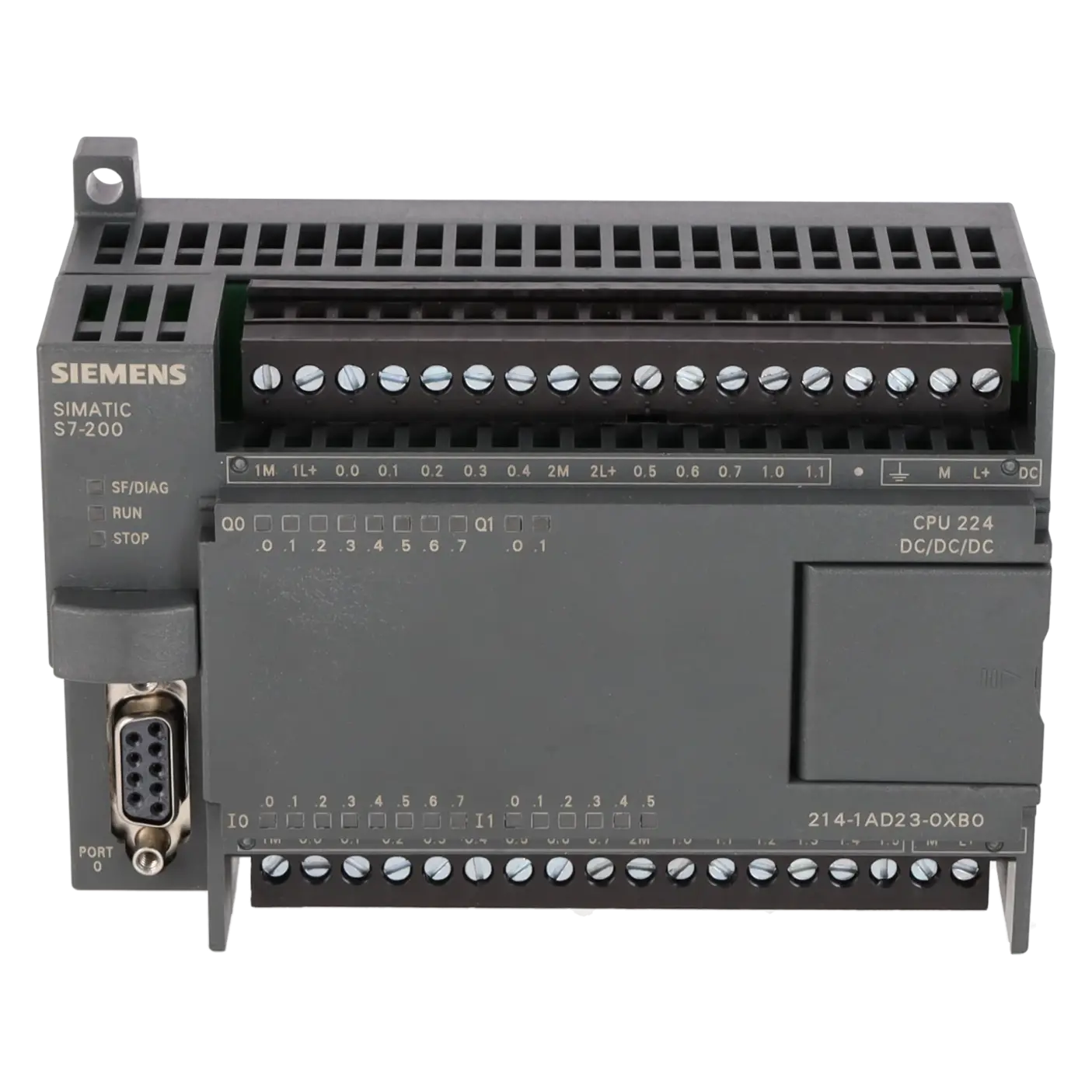
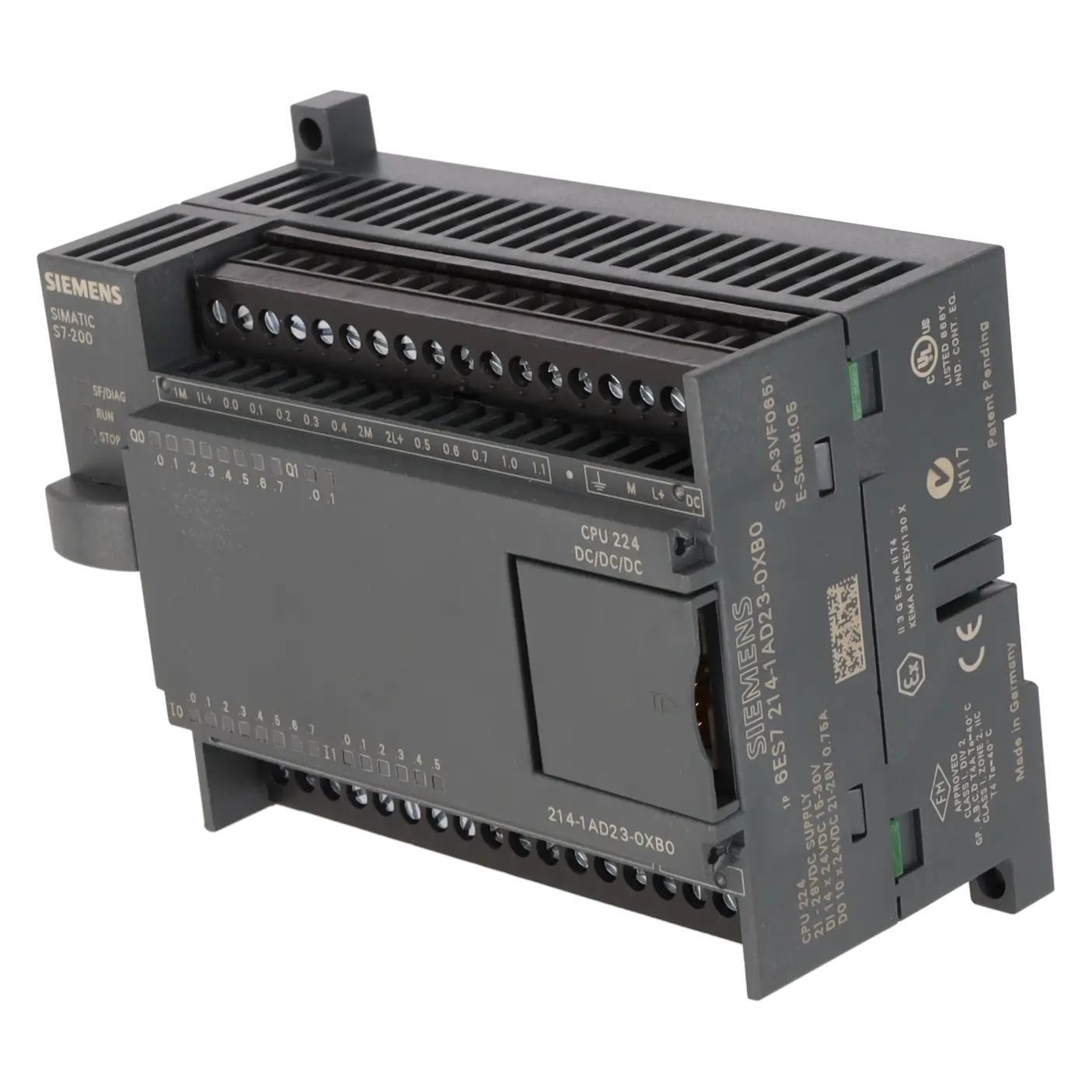
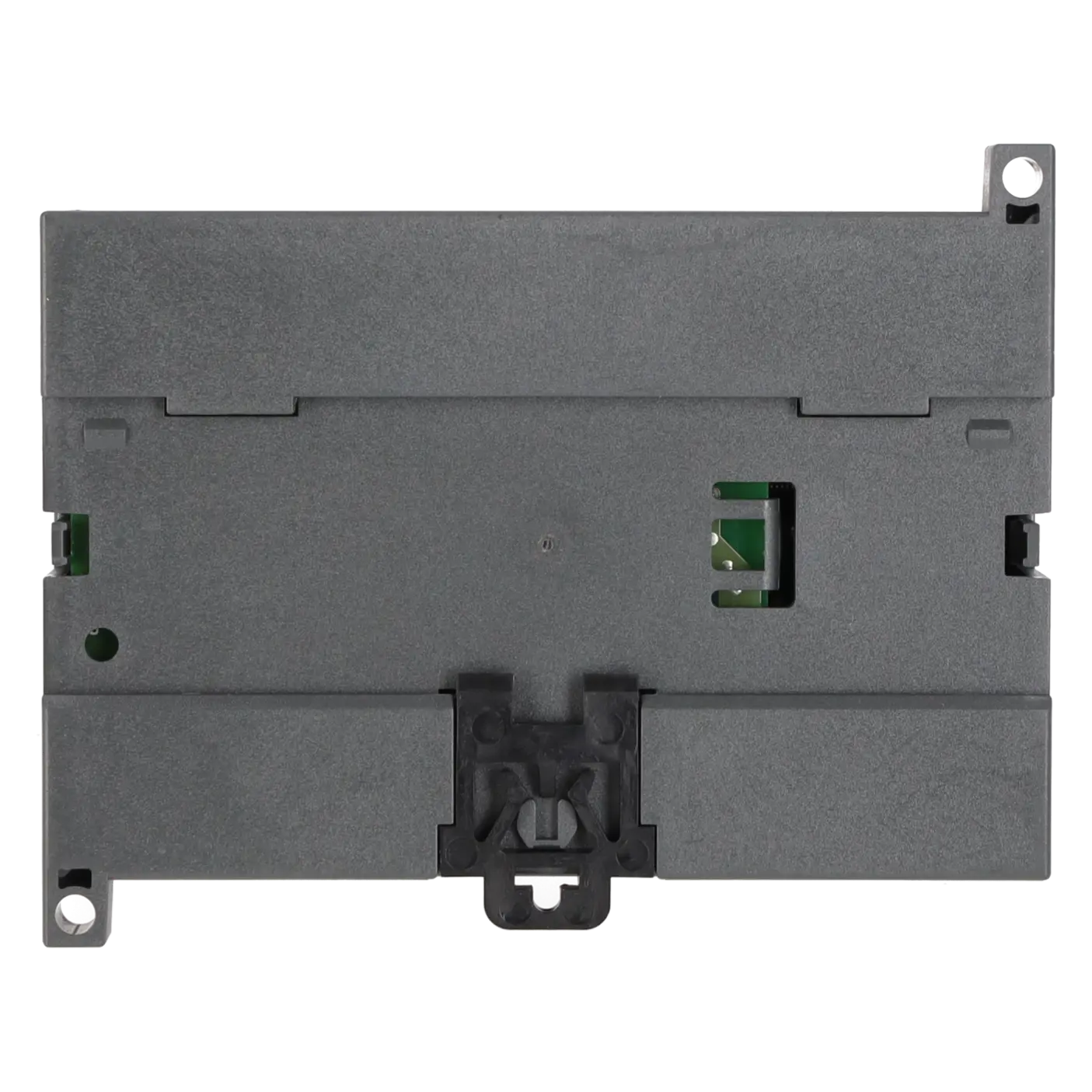
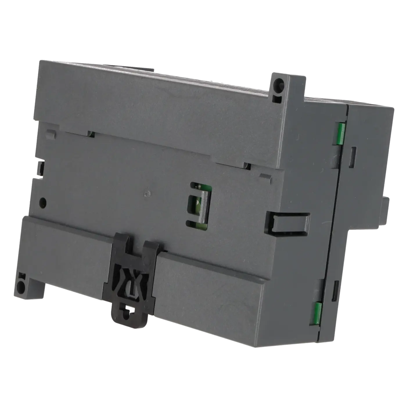
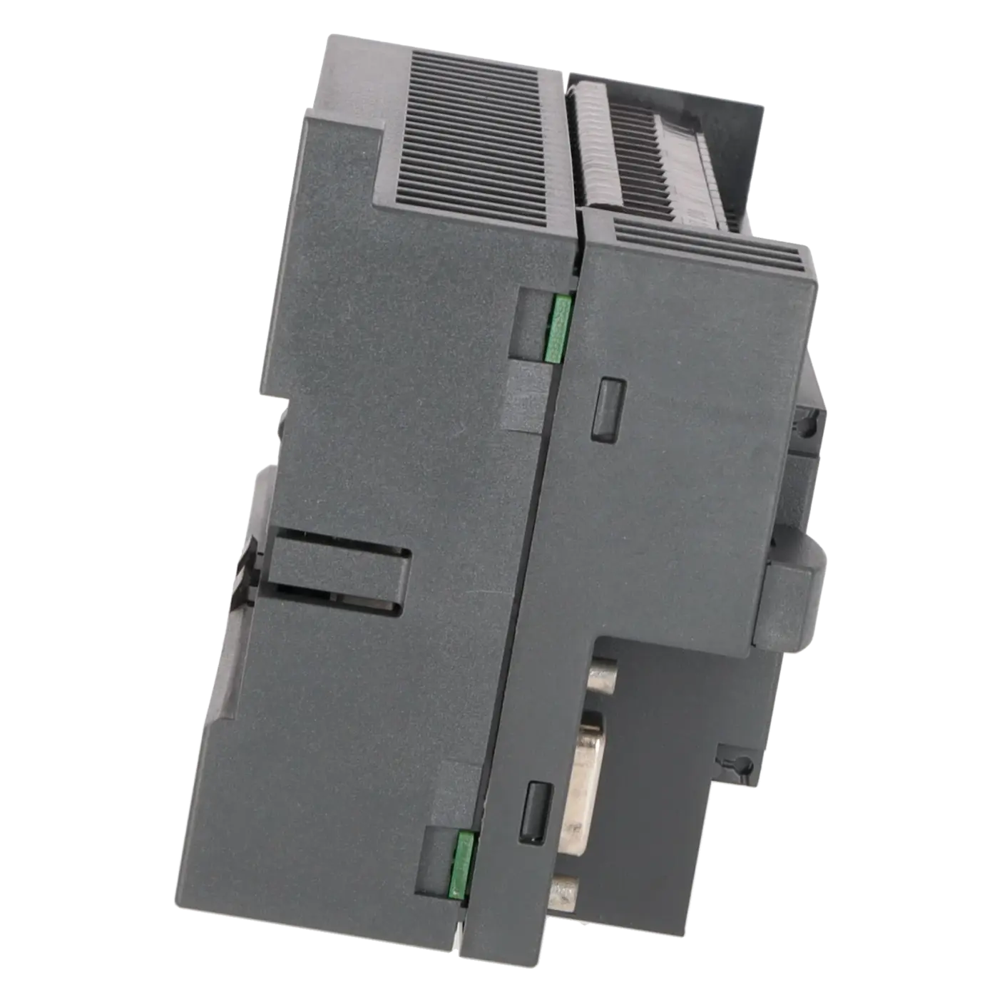
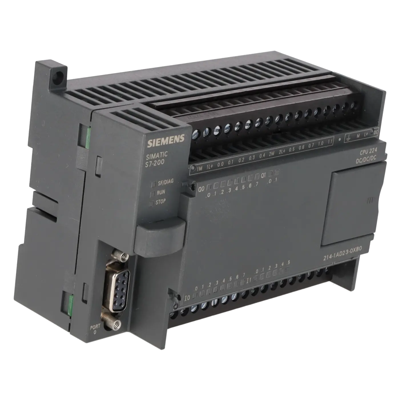
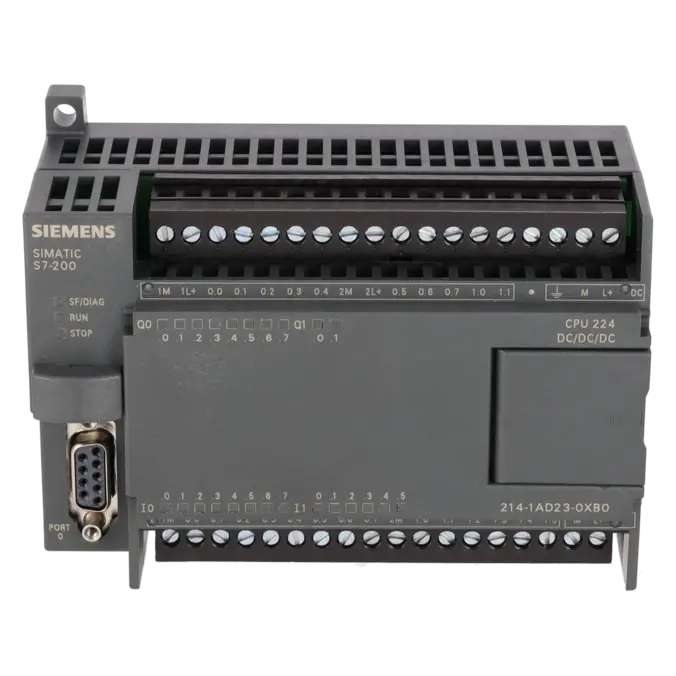
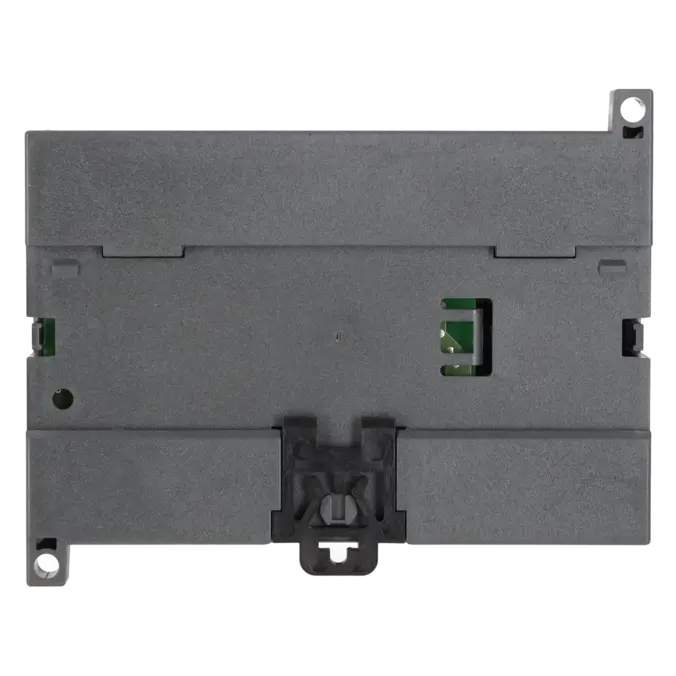
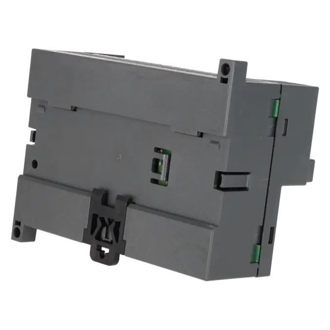
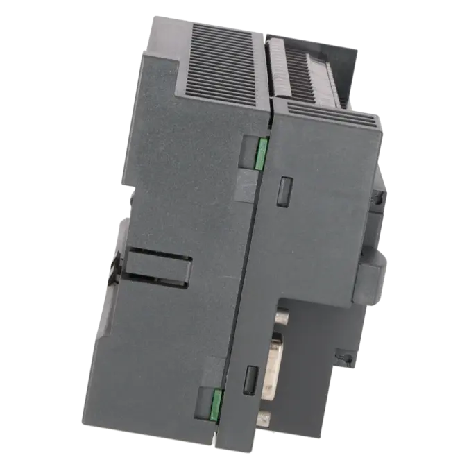
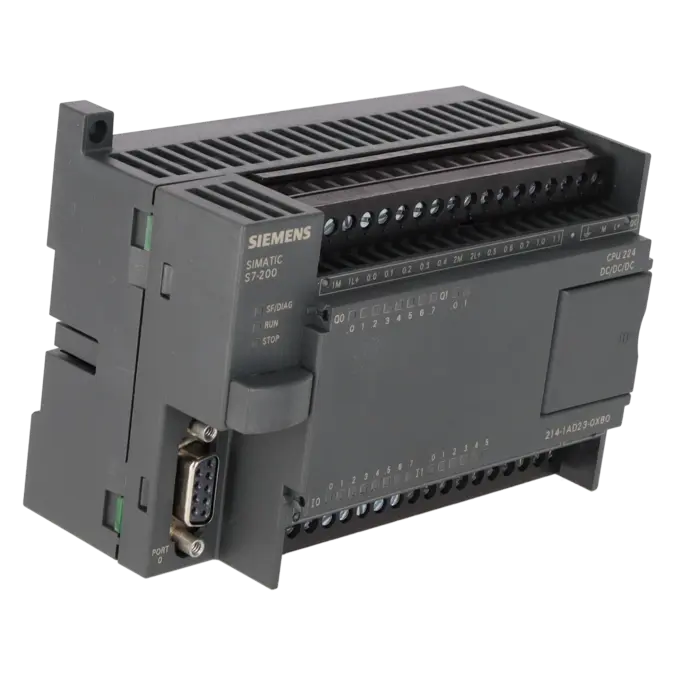
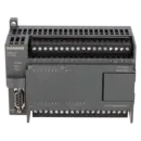
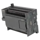
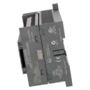
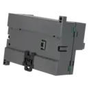
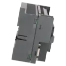
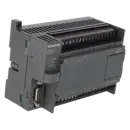
SIMATIC S7-200, CPU 224 KOMPAKTGERAET, DC STROMVERSORG. 14 DE DC/10 DA DC, 8/12 KB PROGR./8 KB DATEN, PROFIBUS DP ERWEITERBAR
Services for SIEMENS 6ES7214-1AD23-0XB0
SIEMENS |
6ES7214-1AD23-0XB0 –
additional product information
| Delivery information | |||
|---|---|---|---|
| Export identifier | AL: ECCN: | ||
| Net weight | 0.342 | ||
| Quantity | 1 Stück | ||
| Packaging quantity | 1 | ||
| Additional product information | |||
|---|---|---|---|
| Product status | EOP: 2017-10-01 | ||
| EAN | 4025515070993 | ||
| UPC | / | ||
| Static lot number | 85371091 | ||
| List indicator | / | ||
| Product group | 4255 | ||
| Country of origin | CN | ||
| Compliance with the substance restrictions according to RoHS directive | Since: / | ||
| Product classifications | Version | Classification | |
|---|---|---|---|
| eClass | 4 | / | |
| eClass | 5.1 | / | |
| eClass | 6.0 | / | |
| ETIM | 3 | / | |
| ETIM | 4 | / | |
| ETIM | 5 | / | |
What is 6ES7214-1AD23-0XB0 and where is it used?
The 6ES7214-1AD23-0XB0 is a SIEMENS SIMATIC S7-200 CPU 224 compact controller designed for small to medium-sized automation tasks in machine and plant applications. The unit operates from 24 V DC and provides 14 digital inputs and 10 digital transistor outputs, making it a typical solution for legacy installations where robust and space-saving PLC technology is required. The CPU is commonly used in compact machinery, conveyor and handling systems, auxiliary control applications and retrofit projects where an existing S7-200 architecture is to remain in service. For maintenance personnel, it is particularly relevant when an identical replacement unit is required to minimise modification work, software changes and production downtime.
Overview of the key technical data and what they mean
The CPU 224 provides a feature set that is well suited to many legacy machine applications: 12 kB of program memory, or 8 kB when Run-Time Edit is enabled, 8 kB of data memory, a 24 V DC supply, 6 high-speed counters up to 30 kHz, 2 pulse outputs up to 20 kHz, and an integrated RS-485 interface supporting PPI, MPI slave operation and free serial communication. The controller can be expanded with up to 7 S7-22x expansion modules. In practice, this means the CPU is suitable for conventional discrete control tasks, basic counting and pulse applications, and existing systems requiring HMI or field communication. The 10 transistor outputs are particularly useful for fast switching applications but require proper load sizing and suitable protective circuitry.
Product status, life-cycle status and obsolescence
For procurement purposes, the product status is an important consideration. The EICHLER product page lists an EOP (End of Product) date of 2017-10-01 for this part number. Siemens product information classifies the 6ES7214-1AD23-0XB0 as an obsolete product and spare part. Following the phase-out of the S7-200 family, Siemens recommends migration to the SIMATIC S7-1200, which is identified in Siemens migration documentation as the successor platform to the S7-200 series. However, this does not imply a simple plug-and-play replacement for existing machines. In many maintenance scenarios, an identical replacement CPU, a professional repair or a planned migration project remains the most practical and economically sound approach.
Available EICHLER services and when they are relevant
Several service options are available from EICHLER for this CPU, including repair, exchange, used units and new units on request. Repair is particularly beneficial when the existing application software, wiring and machine logic should remain unchanged. According to EICHLER, the repair service includes technical cleaning, preventive maintenance, comprehensive functional testing and a minimum 24-month warranty. Exchange services are most appropriate when production downtime is the primary concern and a working replacement is required as quickly as possible. Used CPUs can be an attractive option when an obsolete system needs to remain operational in a cost-effective manner. For purchasing and production departments, these options help maintain supply security even when new units from the manufacturer are only available on a limited basis or by special request.
| Attribute | Value |
|---|---|
| Supply voltage | |
| Rated value (DC) | |
| ● 24 V DC | Yes |
| Load voltage L+ | |
| ● Rated value (DC) | 24 V |
| ● permissible range, lower limit (DC) | 20.4 V |
| ● permissible range, upper limit (DC) | 28.8 V |
| Input current | |
| Inrush current, max. | 12 A; at 28.8 V |
| from supply voltage L+, max. | 700 mA; 110 mA to 700 mA, output current for expansion modules (5 V DC) 660 mA |
| Encoder supply | |
| 24 V encoder supply | |
| ● 24 V | Yes; permissible range: 15.4 to 28.8 V |
| ● Short-circuit protection | Yes; electronic at 280 mA |
| ● Output current, max. | 280 mA |
| Power loss | |
| Power loss, typ. | 7 W |
| Memory | |
| Number of memory modules (optional) | 1; pluggable memory module, content identical with integral EEPROM; can additionally store recipes, data logs and other files |
| Work memory | |
| ● integrated (for program) | 12 kbyte; 8 KB with active run-time edit |
| ● integrated (for data) | 8 kbyte |
| Backup | |
| ● present | Yes; Program: Entire program maintenance-free on integral EEPROM, programmable via CPU; data: Entire DB 1 loaded from PG/PC maintenance-free on integral EEPROM, current values of DB 1 in RAM, retentive memory bits, timers, counters, etc. maintenance-free via high-performance capacitor; optional battery for long-term buffering |
| Battery | |
| Backup battery | |
| ● Backup time, max. | 100 h; (min. 70 h at 40 °C); 200 days (typ.) with optional battery module |
| CPU processing times | |
| for bit operations, max. | 0.22 µs |
| Counters, timers and their retentivity | |
| S7 counter | |
| ● Number | 256 |
| Retentivity | |
| — adjustable | Yes; via high-performance capacitor or battery |
| Counting range | |
| — lower limit | 0 |
| — upper limit | 32 767 |
| S7 times | |
| ● Number | 256 |
| Retentivity | |
| — adjustable | Yes; via high-performance capacitor or battery |
| Time range | |
| — lower limit | 1 ms |
| — upper limit | 54 min; 4 timers: 1 ms to 30 s; 16 timers: 10 ms to 5 min; 236 timers: 100 ms to 54 min |
| Data areas and their retentivity | |
| Flag | |
| ● Size, max. | 32 byte |
| ● Retentivity available | Yes; M 0.0 to M 31.7 |
| ● of which retentive with battery | 0 to 255, via high-performance capacitor or battery, adjustable |
| ● of which retentive without battery | 0 to 112 in EEPROM, adjustable |
| Hardware configuration | |
| Number of expansion units, max. | 7; Only expansion modules of the S7-22x series can be used. Due to the limited output current, the use of expansion modules may be limited. |
| connectable programming devices/PCs | SIMATIC PG/PC, standard PC |
| Expansion modules | |
| ● Analog inputs/outputs, max. | 35; max. 28 inputs and 7 outputs (EM) or max. 0 inputs and 14 outputs (EM) |
| ● Digital inputs/outputs, max. | 168; max. 94 inputs and 74 outputs (CPU + EM) |
| ● AS-Interface inputs/outputs, max. | 62; AS-Interface A/B slaves (CP 243-2) |
| Digital inputs | |
| Number of digital inputs | 14 |
| Sourcing/sinking input | Yes; optionally, per group |
| Input voltage | |
| ● Rated value (DC) | 24 V |
| ● for signal "0" | 0 to 5 V |
| ● for signal "1" | min. 15 V |
| Input current | |
| ● for signal "1", typ. | 2.5 mA |
| Input delay (for rated value of input voltage) | |
| for standard inputs | |
| — parameterizable | Yes; all |
| — at "0" to "1", min. | 0.2 ms |
| — at "0" to "1", max. | 12.8 ms |
| for interrupt inputs | |
| — parameterizable | Yes; I 0.0 to I 0.3 |
| for technological functions | |
| — parameterizable | Yes; (E 0.0 to E 1.5) 30 kHz |
| Cable length | |
| ● shielded, max. | 500 m; Standard input: 500 m, high-speed counters: 50 m |
| ● unshielded, max. | 300 m; not for high-speed signals |
| Digital outputs | |
| Number of digital outputs | 10; Transistor |
| Short-circuit protection | No; to be provided externally |
| Limitation of inductive shutdown voltage to | 1 W |
| Switching capacity of the outputs | |
| ● with resistive load, max. | 0.75 A |
| ● on lamp load, max. | 5 W |
| Output voltage | |
| ● for signal "1", min. | 20 V DC |
| Output current | |
| ● for signal "1" rated value | 750 mA |
| ● for signal "0" residual current, max. | 10 µA |
| Output delay with resistive load | |
| ● "0" to "1", max. | 15 µs; of the standard outputs, max. (Q 0.2 to Q 1.1) 2 µs; of the pulse outputs, max. (Q 0.0 to Q 0.1) 2 µs |
| ● "1" to "0", max. | 130 µs; of the standard outputs, max. (Q 0.2 to Q 1.1) 10 µs; of the pulse outputs, max. (Q 0.0 to Q 0.1) 10 µs |
| Parallel switching of two outputs | |
| ● for uprating | Yes |
| Switching frequency | |
| ● of the pulse outputs, with resistive load, max. | 20 kHz; Q0.0 to Q0.1 |
| Total current of the outputs (per group) | |
| all mounting positions | |
| — up to 40 °C, max. | 6 A |
| horizontal installation | |
| — up to 55 °C, max. | 6 A |
| Relay outputs | |
| ● Number of relay outputs | 0 |
| Cable length | |
| ● shielded, max. | 500 m |
| ● unshielded, max. | 150 m |
| Analog inputs | |
| Number of analog potentiometers | 2; Analog potentiometer; resolution 8 bit |
| Encoder | |
| Connectable encoders | |
| ● 2-wire sensor | Yes |
| — permissible quiescent current (2-wire sensor), max. | 1 mA |
| 1. Interface | |
| Interface type | Integrated RS 485 interface |
| Protocols | |
| ● MPI | Yes; As MPI slave for data exchange with MPI masters (S7-300/S7-400 CPUs, OPs, TDs, Push Button Panels); S7-200-internal CPU/CPU communication is possible in the MPI network with restrictions; transmission rates: 19.2/187.5 kbit/s |
| ● PPI | Yes; with PPI protocol for program functions, HMI functions (TD 200, OP), S7-200-internal CPU/CPU communication ; transmission rates 9.6/19.2/187.5 kbit/s |
| ● serial data exchange | Yes; As freely programmable interface with interrupt facility for serial data exchange with third-party devices with ASCII protocol transfer rates: 1.2 / 2.4 / 4.8 / 9.6 / 19.2 / 38.4 / 57.6 / 115.2 kbps; the PC/PPI cable can also be used as RS 232/RS 485 converter |
| MPI | |
| ● Transmission rate, min. | 19.2 kbit/s |
| ● Transmission rate, max. | 187.5 kbit/s |
| Integrated Functions | |
| Counter | |
| ● Number of counters | 6; High-speed counters (30 kHz each), 32 bit (incl. sign), can be used as up/down counters or for connecting 2 incremental encoders with 2 pulse trains offset by 90° (max. 20 kHz (A/B counters)); parameterizable enable and reset input; interrupt facilities (incl. call of subroutine with any content) when the setpoint is reached; reversal in counting direction, etc. |
| ● Counting frequency, max. | 30 kHz |
| Number of alarm inputs | 4; 4 rising edges and/or 4 falling edges |
| Number of pulse outputs | 2; High-speed outputs, 20 kHz, with interrupt option; pulse-width and frequency modulation option |
| Limit frequency (pulse) | 20 kHz |
| Potential separation | |
| Potential separation digital inputs | |
| ● between the channels | Yes |
| ● between the channels, in groups of | 6 and 8 |
| Potential separation digital outputs | |
| ● between the channels | Yes; Optocoupler |
| ● between the channels, in groups of | 5 |
| Permissible potential difference | |
| between different circuits | 500 V DC between 24 V DC and 5 V DC |
| Degree and class of protection | |
| IP degree of protection | IP20 |
| Ambient conditions | |
| Ambient temperature during operation | |
| ● horizontal installation, min. | 0 °C |
| ● horizontal installation, max. | 55 °C |
| ● vertical installation, min. | 0 °C |
| ● vertical installation, max. | 45 °C |
| Air pressure acc. to IEC 60068-2-13 | |
| ● permissible range, lower limit | 860 hPa |
| ● permissible range, upper limit | 1 080 hPa |
| Relative humidity | |
| ● Operation, min. | 5 % |
| ● Operation, max. | 95 %; RH class 2 in accordance with IEC 1131-2 |
| Configuration | |
| Programming | |
| ● Command set | Bit logic instructions, compare instructions, timer instructions, counter instructions, clock instructions, transmissions instructions, table instructions, logic instructions, shift and rotate instructions, conversion instructions, program control instructions, interrupt and communications instructions, logic stack instructions, integer maths, floating-point math instructions, numerical functions |
| ● Program processing | free cycle (OB 1), interrupt-controller, time-controlled (1 to 255 ms) |
| ● Program organization | 1 OB, 1 DB, 1 SDB subroutines with/without parameter transfer |
| ● Number of subroutines, max. | 64 |
| Programming language | |
| — LAD | Yes |
| — FBD | Yes |
| — STL | Yes |
| Know-how protection | |
| ● User program protection/password protection | Yes; 3-stage password protection |
| Connection method | |
| Plug-in I/O terminals | Yes |
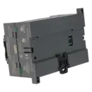
| Dimensions | |
| Width | 120.5 mm |
| Height | 80 mm |
| Depth | 62 mm |
| Weights | |
| Weight, approx. | 360 g |
| Fault description | Possible solution |
|---|---|
| Why are the SF and STOP LEDs illuminated on my S7-200 CPU 224 and the system will not start? | In the event of a serious fault, the CPU switches to STOP mode, activates the SF and STOP LEDs and deactivates the outputs. In STEP 7-Micro/WIN, the fault status and error code should be read first. Siemens identifies common causes such as watchdog time errors, indirect addressing problems, invalid comparison operations, electrical interference and hardware faults. After correcting the root cause, the CPU must be restarted, for example by cycling the power supply, switching the CPU to STOP and back to RUN, or using Target System > Reset on Startup. |
| Why do I receive a "Communications time-out" message and cannot go online with the S7-200 CPU 224? | First check the configured COM port, network address, baud rate and communication adapter. The S7-200 uses PPI communication via RS-485; Siemens specifies adapters such as the USB/PPI cable 6ES7901-3DB30-0XA0. The default network address is 2 and the default baud rate is 9.6 kbaud. When using a classic PC/PPI cable, the DIP switch settings must also match the selected baud rate. In Micro/WIN, ensure that the correct access path for PC/PPI or USB/PPI communication is configured. |
| Why does the CPU 224 lose data, counter values or marker values after a power failure? | Not all memory areas are retained automatically. Siemens specifies that retentive areas for V, M, C and T memory must be configured explicitly. The user program and DB1 are stored in EEPROM, whereas other RAM contents remain available only if they are configured as retentive or are correctly battery-backed. The official backup time without an optional battery module is up to 100 hours, with significantly longer retention typically achieved only when an additional battery is installed. If these symptoms occur, both the retentive memory configuration and the backup concept should be checked carefully. |
| Why does my S7-200 CPU 224 report an EEPROM fault or fail after frequent save operations? | Siemens recommends using EEPROM write operations only for important and infrequent events. Data can be stored in a power-fail-safe manner using SMB31 and SMW32, but the number of write cycles is limited. The system manual specifies a minimum of 100,000 write cycles and typically 1,000,000 write cycles. If data is written to EEPROM during every PLC scan cycle, the memory can wear out prematurely. During troubleshooting, verify whether the user program performs cyclical EEPROM writes instead of saving data only when specific events occur. |
| Why does an output on the CPU 224 no longer switch even though the controller is in RUN mode? | First verify in the diagnostic tools or program status that the logic is actually commanding the output. In many cases, the root cause is not the CPU itself but missing interlocks, sensor conditions, enable signals or addressing errors. If the output is definitely being activated in software but the load still does not switch, the load circuit, wiring and output hardware should be checked. Siemens also identifies overvoltage on the load side as a common cause of damaged outputs and recommends suitable suppression circuitry when driving inductive loads. |
Do I need special software for 6ES7214-1AD23-0XB0?
Yes. The SIMATIC S7-200 CPU 224 is programmed and diagnosed using STEP 7-Micro/WIN. Siemens specifies STEP 7-Micro/WIN V4.0 as the engineering software for the S7-200 family, with Service Packs SP8 and SP9 supporting all S7-200 CPUs of the 21x and 22x series. For maintenance and backup purposes, this is particularly important because reliable diagnostics, program uploads and downloads cannot be performed without a compatible Micro/WIN environment. For legacy systems, it is therefore essential to maintain not only the CPU but also the corresponding engineering software.
Which cable do I need to upload a program from or download a backup to the CPU 224?
The CPU features an integrated RS-485 interface and supports PPI, MPI slave and free serial communication. Siemens specifically recommends the USB/PPI Multi-Master cable 6ES7901-3DB30-0XA0 for PC connection. Older installations may also use a PC/PPI cable connected to a serial PC interface. This is particularly relevant for service work, as communication issues are often caused by an unsuitable adapter. Before creating a backup, performing diagnostics or loading a replacement CPU, the correct PPI-capable communication path should always be verified.
How far can the CPU 224 be expanded?
The CPU 224 can be expanded with up to seven S7-22x expansion modules. Siemens specifies expansion limits of up to 168 digital inputs and outputs, together with additional analogue and communication functions depending on the modules installed. For existing machines, this is important because many upgrades can be achieved by replacing or adding S7-200 components rather than performing a complete PLC migration. For purchasing and maintenance departments, the availability of compatible expansion modules is therefore just as important as the CPU itself.
Is 6ES7214-1AD23-0XB0 discontinued or still part of the active Siemens portfolio?
The 6ES7214-1AD23-0XB0 is no longer in the active product lifecycle. EICHLER lists an EOP (End of Production) date of 1 October 2017, and Siemens classifies the module as obsolete or spare part only. For new applications, Siemens recommends migrating to the SIMATIC S7-1200 platform following the phase-out of the S7-200 family. For operators of existing systems, this means that procurement strategies, spare-part stocking, repair capabilities and specialist service providers become increasingly important, as standard manufacturer supply is no longer the primary option.
What communication options does the CPU 224 support?
The CPU 224 includes an integrated RS-485 interface. It supports PPI for programming and HMI communication, MPI slave mode for data exchange with MPI masters, and free serial communication using ASCII protocols. According to the product documentation, the CPU can also be expanded for PROFIBUS-DP communication. Siemens notes that S7-22x CPUs without an integrated DP interface require an appropriate communication module when PROFIBUS-DP communication above 187.5 kbaud is required. This is particularly important when retaining existing communication structures during retrofits, HMI replacements or network modifications.
When is repair more economical than replacement for 6ES7214-1AD23-0XB0?
Repair is often the preferred option when the machine should continue operating with its existing hardware and software configuration and no engineering changes are desired. Replacement is generally the better choice when minimising downtime is the highest priority and an immediately available functional unit is required. EICHLER offers repair, exchange, used and new on request options for this CPU. The repair service includes technical cleaning, preventive maintenance, comprehensive functional testing and a minimum 24-month warranty. For decision-makers, this is particularly relevant when balancing obsolescence risks, component availability and production continuity.