
SIEMENS 6ES7332-5HB01-0AB0
-
SIEMENS | PLC Controls | Analog Input / Output Modules
- EICHLER-art.no.: K0118583
- EAN: 4025515061267
- UPC: 662643177961
Product description
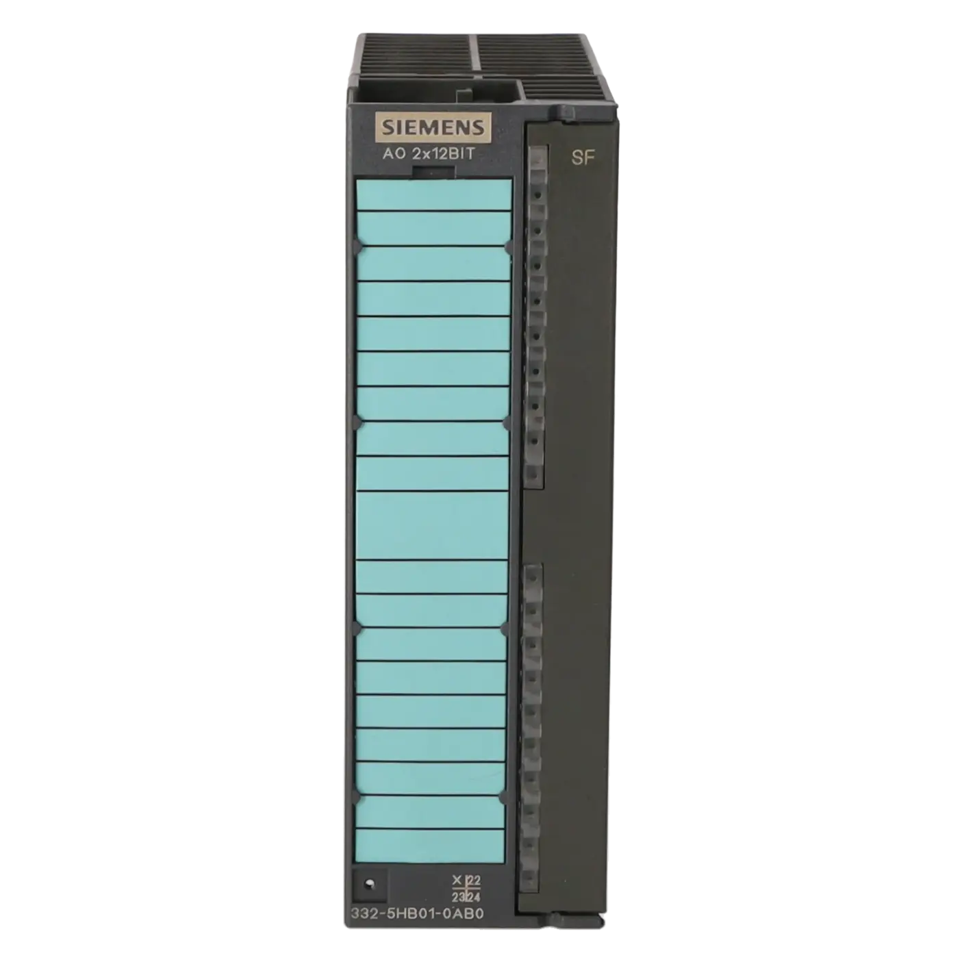
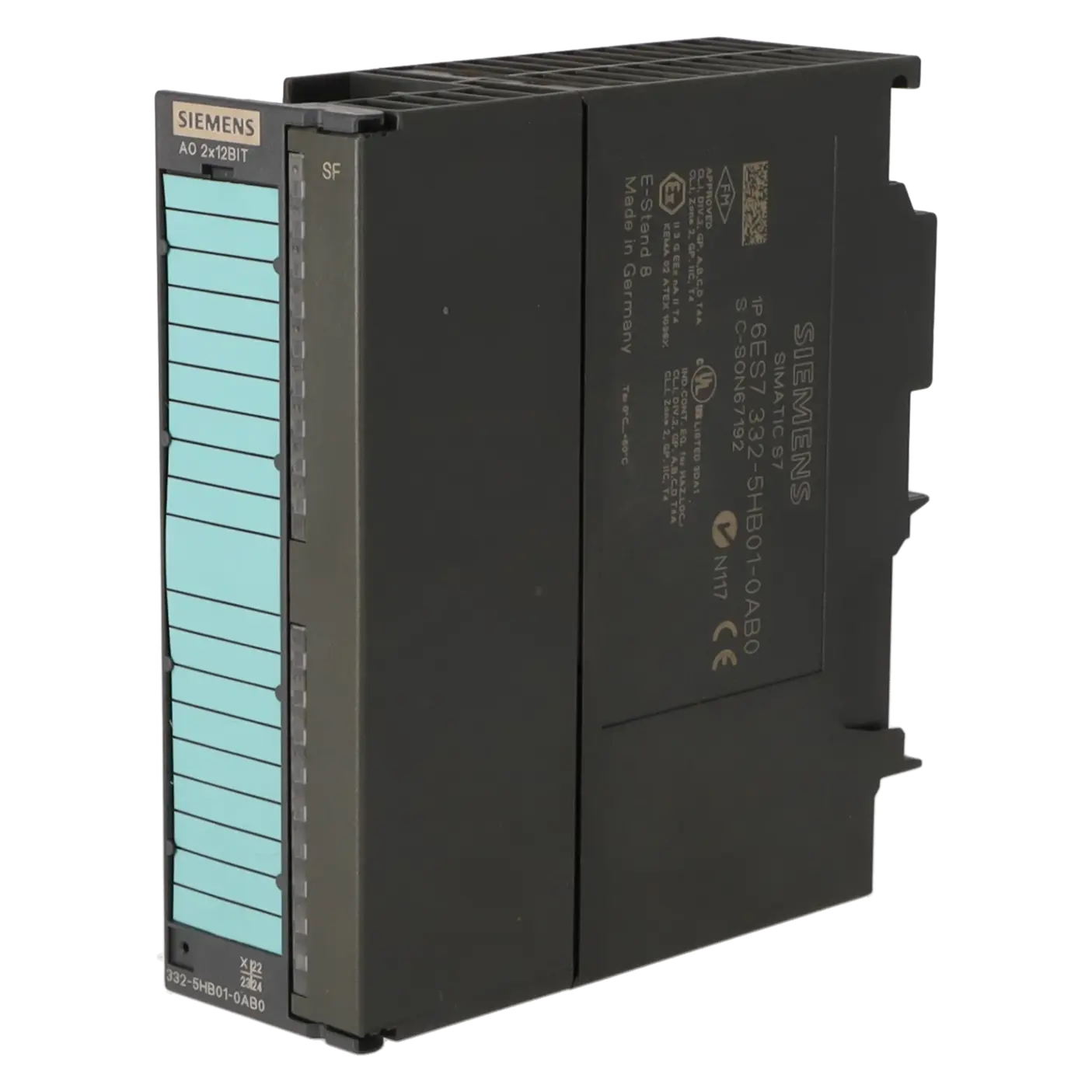
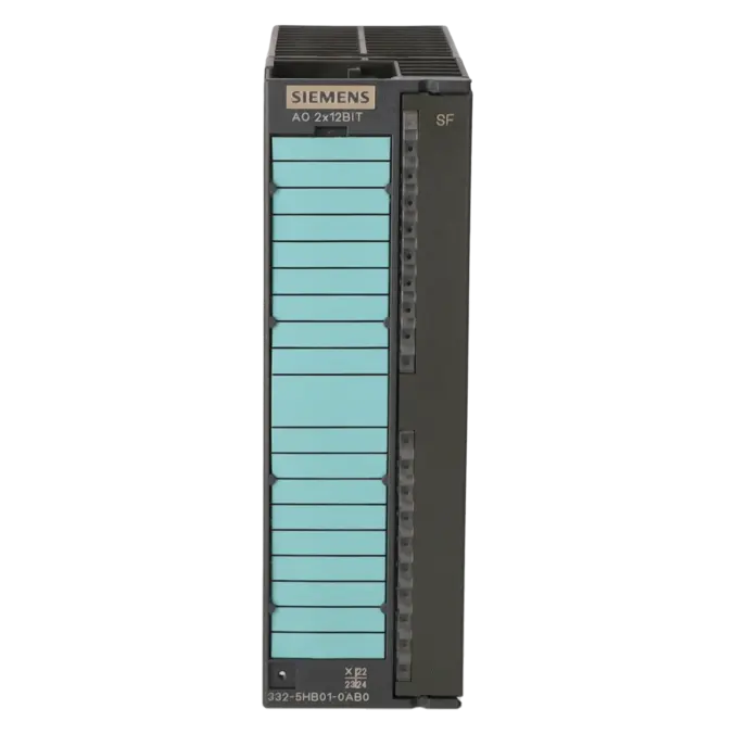
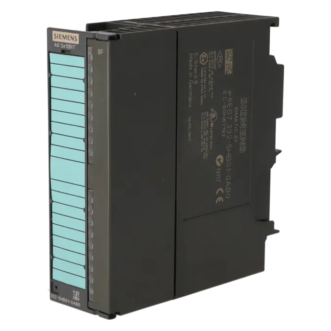
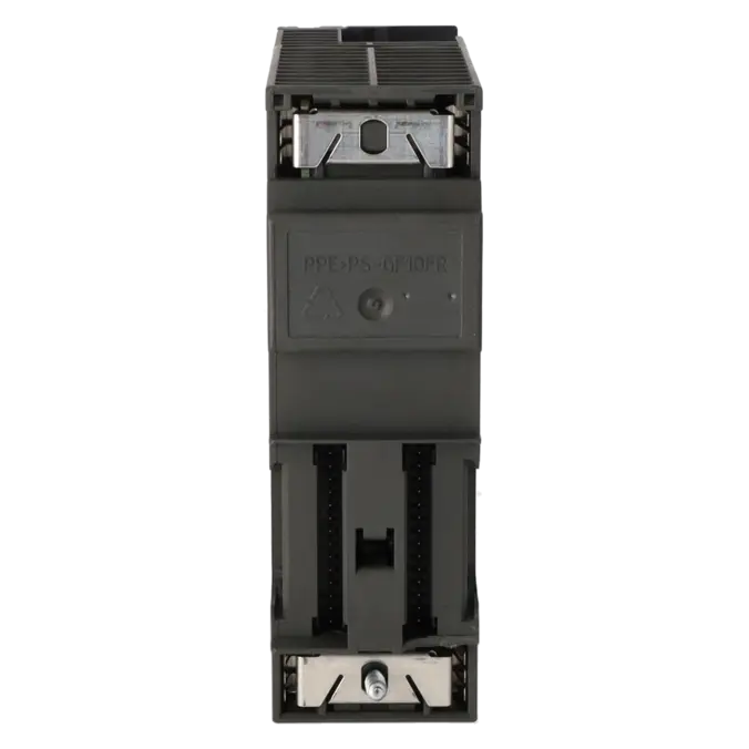
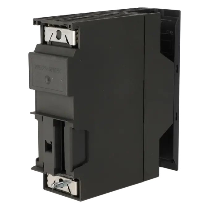
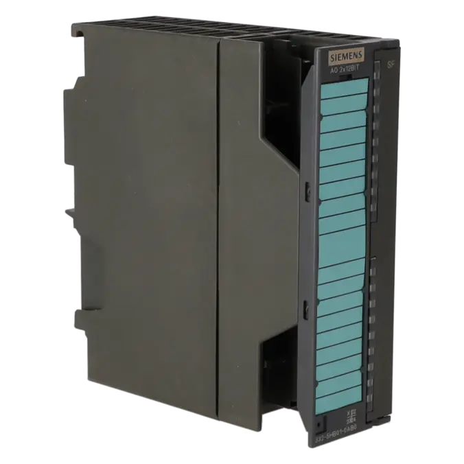
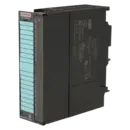
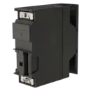
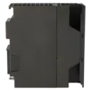
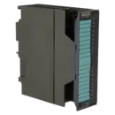
SIMATIC S7-300, ANALOG OUTPUT SM 332, ISOLATED, 2 AO, U/I; RESOLUTION 11/12 BITS, 20-POLE, REMOVING/INSERTING WITH ACTIVE BACKPLANE BUS POSSIBLE
Services for SIEMENS 6ES7332-5HB01-0AB0
Repair
from 334,31 €
to 601,76 €
Replacement
356,48 €
267,36 €
Used
499,99 €
374,99 €
New
602,80 €
452,10 €
SIEMENS |
6ES7332-5HB01-0AB0 –
additional product information
| Delivery information | |||
|---|---|---|---|
| Export identifier | AL: N ECCN: EAR99H | ||
| Net weight | 0.246 | ||
| Quantity | 1 Stück | ||
| Packaging quantity | 1 | ||
| Additional product information | |||
|---|---|---|---|
| Product status | EOP: 2025-10-01 | ||
| EAN | 4025515061267 | ||
| UPC | 662643177961 | ||
| Static lot number | 85389091 | ||
| List indicator | ST73 | ||
| Product group | 4561 | ||
| Country of origin | DE | ||
| Compliance with the substance restrictions according to RoHS directive | Since: 20080331 | ||
| Product classifications | Version | Classification | |
|---|---|---|---|
| eClass | 4 | 27-24-03-05 | |
| eClass | 5.1 | 27-24-22-01 | |
| eClass | 6.0 | 27-24-22-01 | |
| ETIM | 3 | / | |
| ETIM | 4 | EC001420 | |
| ETIM | 5 | EC001420 | |
What is the 6ES7332-5HB01-0AB0 and where is it used?
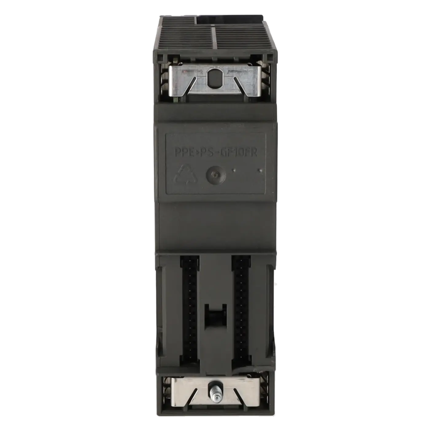
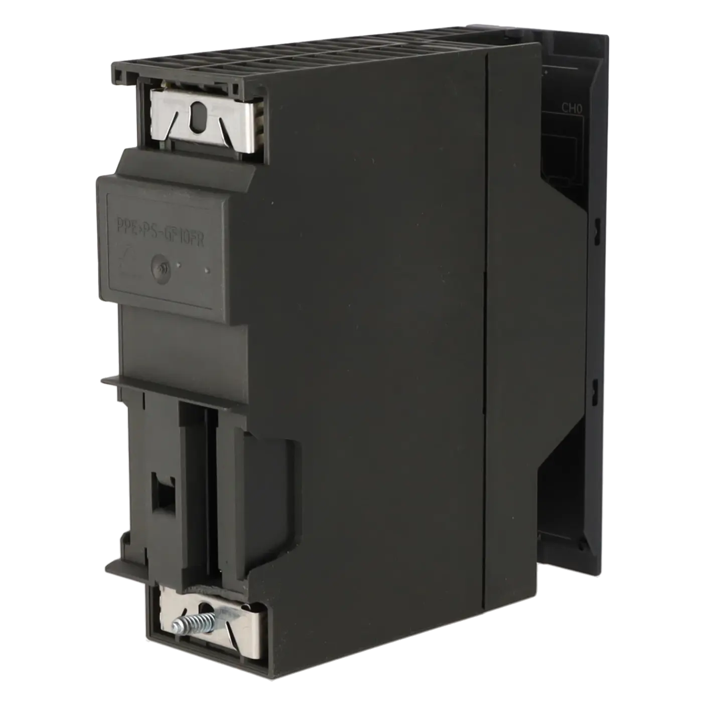
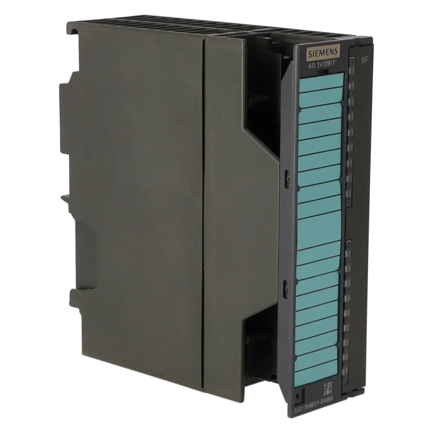
The 6ES7332-5HB01-0AB0 is an SM 332 analogue output module for the SIMATIC S7-300 system. The module provides 2 analogue outputs and is designed for both voltage and current signals. Typical applications include the control of control valves, frequency converters, actuated valves, setpoint interfaces on drives, and the transmission of analogue reference values to process devices in machine and process automation systems. For maintenance engineers, it is particularly important when a reliable replacement of an existing S7-300 analogue output module is required. For purchasing departments, the exact part number is essential because the form factor, connection method, signal ranges and diagnostic behaviour must match the existing installation in order to minimise downtime.
Overview of the key technical data and what they mean
The SM 332 operates with a 24 V DC load supply (L+), provides 2 analogue outputs, and supports 0…10 V, 1…5 V, ±10 V, 0…20 mA, 4…20 mA and ±20 mA signal ranges. Depending on the selected range, it offers 11-bit or 12-bit resolution. The conversion time of 0.8 ms per channel makes it suitable for many control and regulation tasks in industrial automation. In practice, it is important to note that the module is electrically isolated from the backplane bus and load voltage, but not isolated between the two output channels. For current outputs, the maximum permissible load is 500 Ω, while voltage outputs require a minimum load of 1 kΩ. A 20-pin front connector is required. The module dimensions are 40 mm wide, 125 mm high and 117 mm deep.
Product status, life-cycle status and obsolescence
For this module, the EICHLER product page indicates a product status of EOP: 01.10.2025. Siemens lists the 6ES7332-5HB01-0AB0 as a spare part, which is a clear indication that operators should begin planning procurement, stockholding and repair strategies. EICHLER also highlights the discontinuation of the SIMATIC S7-300 and ET 200M product families as of 01.10.2025 and refers to stocked new units. A general 1:1 plug-and-play successor is not clearly identified in the available Siemens documentation. However, Siemens does offer the SIPLUS version 6AG1332-5HB01-2AB0, which is based on this module and intended for applications with extended environmental requirements.
Available EICHLER services and when they are relevant
For the 6ES7332-5HB01-0AB0, EICHLER offers repair, exchange, tested used units and new units. The stated turnaround times are 2–5 days for repairs and 1–3 days for exchange, used and new units. In the context of S7-300 obsolescence, these services are highly practical. An exchange unit helps minimise downtime when a failed module must be replaced immediately. Repair services are particularly attractive for operators who wish to continue running existing installations economically. According to EICHLER, repairs include technical cleaning, preventive maintenance, comprehensive functional testing and a minimum 24-month warranty. For purchasing and production managers, additional benefits include access to tested used units, stocked new devices, on-site services for data backup and system support, and life-cycle management services that help identify supply risks early and establish effective stockholding and replacement strategies for discontinued modules.
| Attribute | Value |
|---|---|
| General information | |
| Product function | |
| ● Isochronous mode | No |
| Supply voltage | |
| Load voltage L+ | |
| ● Rated value (DC) | 24 V |
| ● Reverse polarity protection | Yes |
| Input current | |
| from load voltage L+ (without load), max. | 135 mA |
| from backplane bus 5 V DC, max. | 60 mA |
| Power loss | |
| Power loss, typ. | 3 W |
| Analog outputs | |
| Number of analog outputs | 2 |
| Voltage output, short-circuit protection | Yes |
| Voltage output, short-circuit current, max. | 25 mA |
| Current output, no-load voltage, max. | 18 V |
| Output ranges, voltage | |
| ● 0 to 10 V | Yes |
| ● 1 V to 5 V | Yes |
| ● -10 V to +10 V | Yes |
| Output ranges, current | |
| ● 0 to 20 mA | Yes |
| ● -20 mA to +20 mA | Yes |
| ● 4 mA to 20 mA | Yes |
| Connection of actuators | |
| ● for voltage output two-wire connection | Yes |
| ● for voltage output four-wire connection | Yes |
| ● for current output two-wire connection | Yes |
| Load impedance (in rated range of output) | |
| ● with voltage outputs, min. | 1 kΩ |
| ● with voltage outputs, capacitive load, max. | 1 µF |
| ● with current outputs, max. | 500 Ω |
| ● with current outputs, inductive load, max. | 10 mH |
| Cable length | |
| ● shielded, max. | 200 m |
| Analog value generation for the outputs | |
| Integration and conversion time/resolution per channel | |
| ● Resolution with overrange (bit including sign), max. | 12 bit; ±10 V, ±20 mA, 4 mA to 20 mA, 1 V to 5 V: 11 bit + sign; 0 V to 10 V, 0 mA to 20 mA: 12 bit |
| ● Conversion time (per channel) | 0.8 ms |
| Settling time | |
| ● for resistive load | 0.2 ms |
| ● for capacitive load | 3.3 ms |
| ● for inductive load | 0.5 ms; 0.5 ms (1 mH); 3.3 ms (10 mH) |
| Errors/accuracies | |
| Operational error limit in overall temperature range | |
| ● Voltage, relative to output range, (+/-) | 0.5 % |
| ● Current, relative to output range, (+/-) | 0.6 % |
| Basic error limit (operational limit at 25 °C) | |
| ● Voltage, relative to output range, (+/-) | 0.4 % |
| ● Current, relative to output range, (+/-) | 0.5 % |
| Interrupts/diagnostics/status information | |
| Diagnostics function | Yes; Parameterizable |
| Substitute values connectable | Yes; Parameterizable |
| Alarms | |
| ● Diagnostic alarm | Yes; Parameterizable |
| Diagnoses | |
| ● Diagnostic information readable | Yes |
| Diagnostics indication LED | |
| ● Group error SF (red) | Yes |
| Potential separation | |
| Potential separation analog outputs | |
| ● between the channels | No |
| ● between the channels and backplane bus | Yes |
| ● Between the channels and load voltage L+ | Yes |
| ● between the channels and the power supply of the electronics | Yes |
| Isolation | |
| Isolation tested with | 500 V DC |
| Connection method | |
| required front connector | 20-pin |
| Dimensions | |
| Width | 40 mm |
| Height | 125 mm |
| Depth | 117 mm |
| Weights | |
| Weight, approx. | 220 g |
| Fault description | Possible solution |
|---|---|
| Why does the red SF LED remain lit on the 6ES7332-5HB01-0AB0 even though the module is basically working? | If a diagnostic condition was present before reparameterisation, the SF LED may remain illuminated even though the module is operating correctly again. Check the module diagnostics in STEP 7 or TIA Portal. Only reparameterise the module when no active diagnostics are present. If the LED still remains on, removing and reinserting the module may clear the condition. |
| Why does the module not provide a correct 4–20 mA signal or immediately report an SF fault? | The SM 332 is configured by default for voltage output with a range of ±10 V. For a 4–20 mA actuator, the channel must be explicitly configured in STEP 7 as Current / 4–20 mA. If wire-break diagnostics are enabled and the load is not connected correctly, or the current falls below 4 mA, a diagnostic fault will be generated. Therefore, check the output type, configured range, downloaded hardware configuration, and the actual field wiring. |
| Why is there no output signal at all, or why does the setpoint not reach the field device? | Common causes include output overload, a short circuit to M, a wire break between the module and the actuator, missing L+ load voltage, incorrect front connector wiring, or a problem with the backplane bus connector. A logical troubleshooting sequence is to check the load voltage, inspect the front connector, compare the wiring with the electrical diagram, read the module diagnostics, and verify the backplane bus connector. Only after these checks should the module itself be considered defective. |
| Why do incorrect voltage or current values briefly appear after switching L+ on or off? | Siemens states that the outputs may provide incorrect voltage or current values for approximately 500 ms after the nominal load voltage is switched. In practice, the load voltage should be stable before enabling the actuator. For sensitive control elements, an appropriate start-up sequence should be implemented in which CPU logic, load enable, and the analogue setpoint are activated separately and in the correct order. |
| Why do I get implausible current values, for example around 6 mA, instead of the expected output current? | In many cases, the issue is not the analogue output module itself but the signal scaling in the application software. In practical examples, an incorrect scaling block generated a value at the process output word (PAW) that did not match the configured output range. Verify that the software generates the correct S7 raw value for the configured range (4–20 mA, 0–20 mA, or voltage output). Also confirm that the channel has actually been configured as a current output in the hardware configuration. |
Which output ranges are supported by the 6ES7332-5HB01-0AB0?
The module supports voltage outputs of 0–10 V, 1–5 V and ±10 V, as well as current outputs of 0–20 mA, 4–20 mA and ±20 mA. This is important for operators because it allows the connection of both conventional control valves and drive or process interfaces. The key requirement is that the selected range is correctly configured in the hardware configuration and matched to the actual field wiring.
Which front connector is required for the SM 332 AO 2 x 12 Bit?
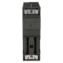
The 6ES7332-5HB01-0AB0 requires a 20-pin front connector. This is particularly important during spare-part procurement and replacement because an incorrect connector type or wiring arrangement can cause unnecessary commissioning issues. Before replacing the module, the condition of the front connector, the terminal assignments, and the field wiring connections should be checked.
Can the 6ES7332-5HB01-0AB0 be removed and inserted while the system is running?
Siemens explicitly states that this module supports removal and insertion with the backplane bus active. While this is useful for maintenance personnel, it does not replace proper maintenance procedures. Before carrying out any intervention, the diagnostic status, the load side, and the risks to connected actuators should be evaluated, as incorrect analogue values can have an immediate impact on the process.
How does the module behave when the CPU is in STOP mode?
For CPU STOP mode, the module can be configured so that the outputs become de-energised, hold their last value, or switch to substitute values. This is particularly important for control loops and drives, as the required behaviour during a fault condition should be defined in advance. Proper configuration helps prevent uncontrolled process reactions when the CPU enters STOP mode.
Is there a successor to the 6ES7332-5HB01-0AB0?
A general 1:1 plug-and-play successor is not clearly identified as a standard replacement in the available documentation. Siemens does, however, offer the SIPLUS version 6AG1332-5HB01-2AB0, which is based on this module and designed for extended environmental conditions. Siemens migration documentation also references a suitable target module within the ET 200SP HA platform for upgrade projects. This should be regarded as a migration option rather than a simple drop-in replacement and should always be evaluated on a project-specific basis.
When is repair more appropriate than exchange or purchasing a new unit?
Repair is generally the best option when the system must be returned to service quickly, the existing configuration should remain unchanged, and retaining the installed module is economically sensible. An exchange unit is often preferable in the event of an unexpected breakdown where an immediately available, fully tested replacement is required. Used units can be attractive for stockholding and cost optimisation in obsolescence situations, while new units are often preferred when building a planned spare-parts inventory or when company procedures require new components. EICHLER combines these options with functional testing, warranty coverage, and additional life-cycle services.