SIEMENS 6ES7331-7RD00-0AB0
-
SIEMENS | PLC Controls | Analog Input / Output Modules
- EICHLER-art.no.: K0118580
- EAN: 4025515061229
- UPC: 662643230253
Product description
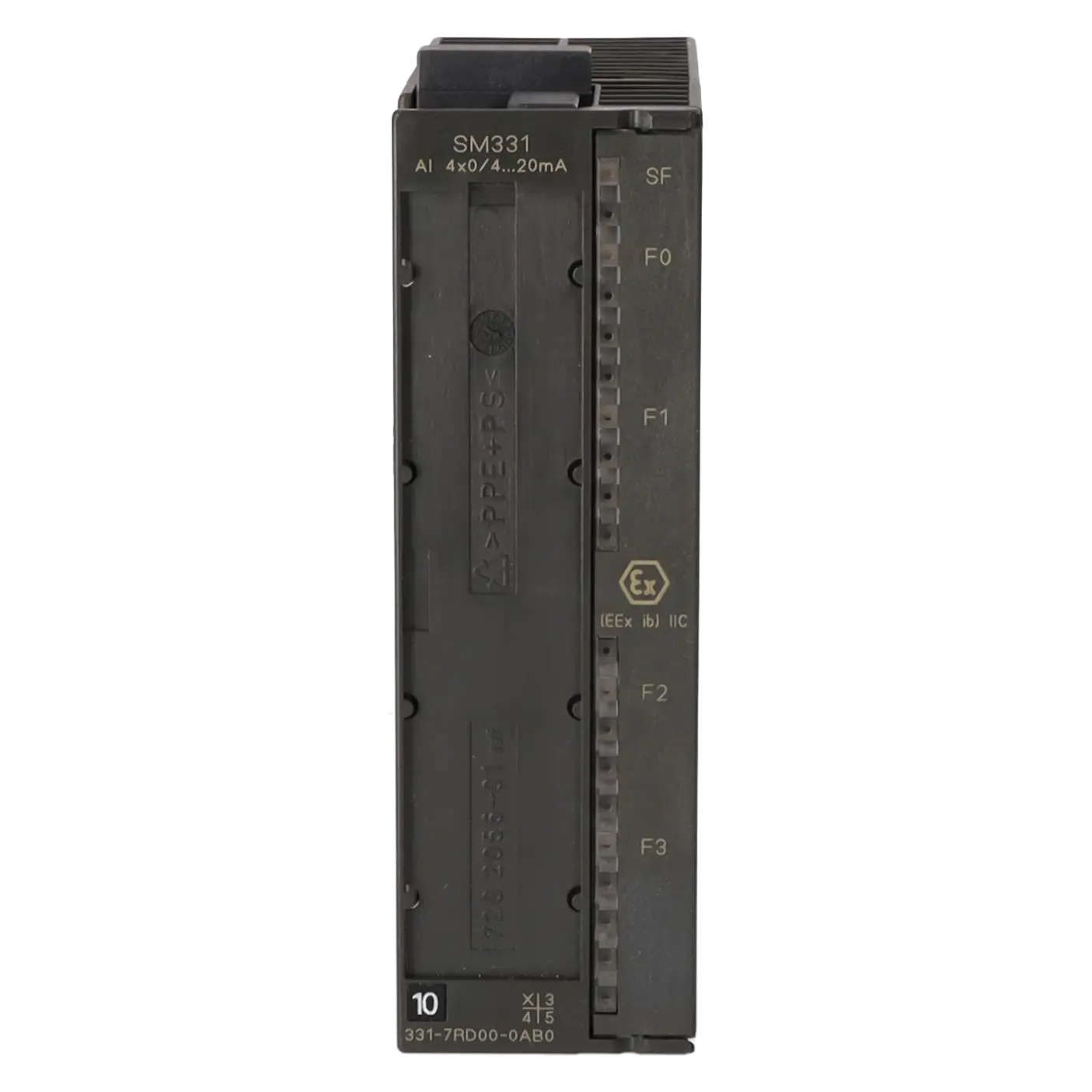
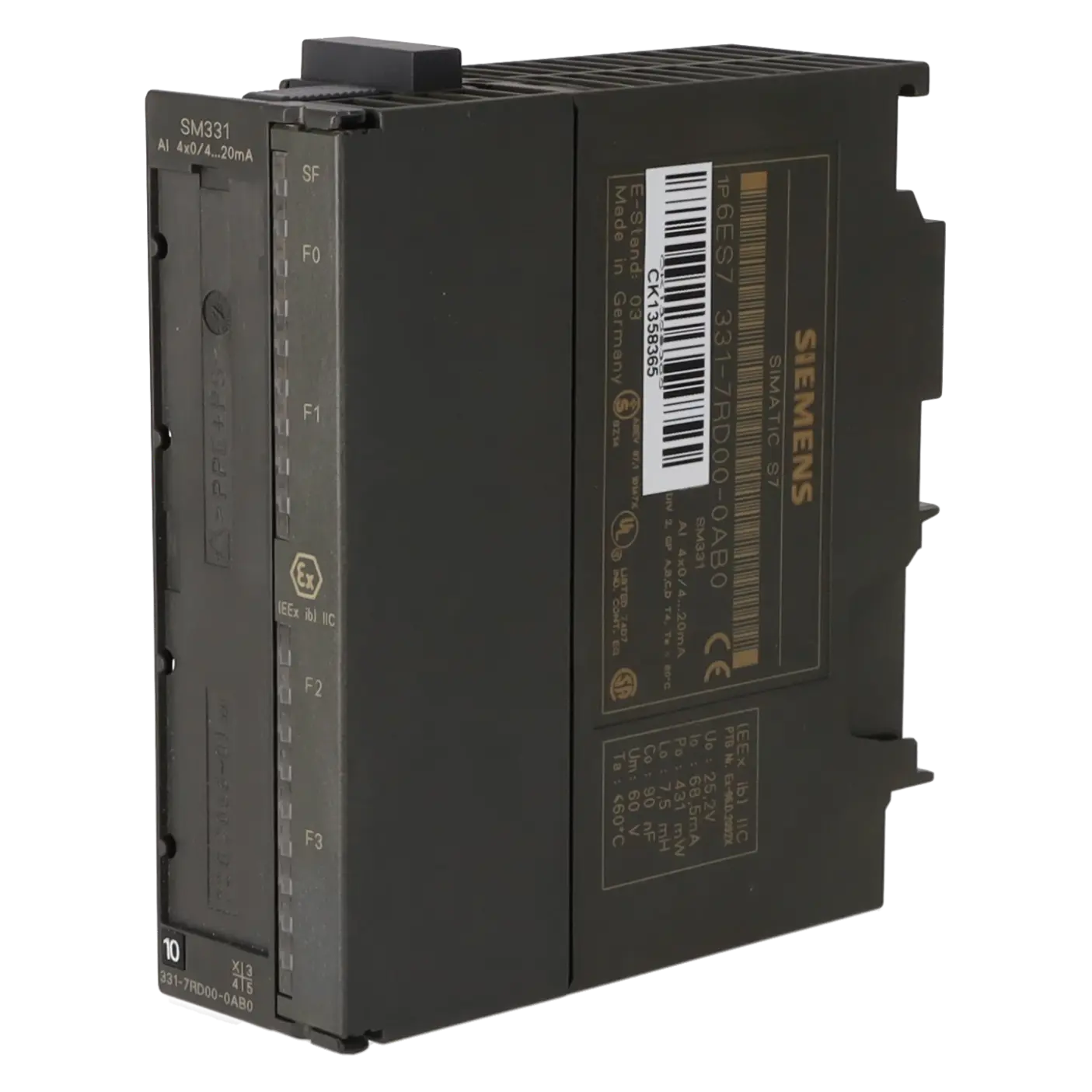
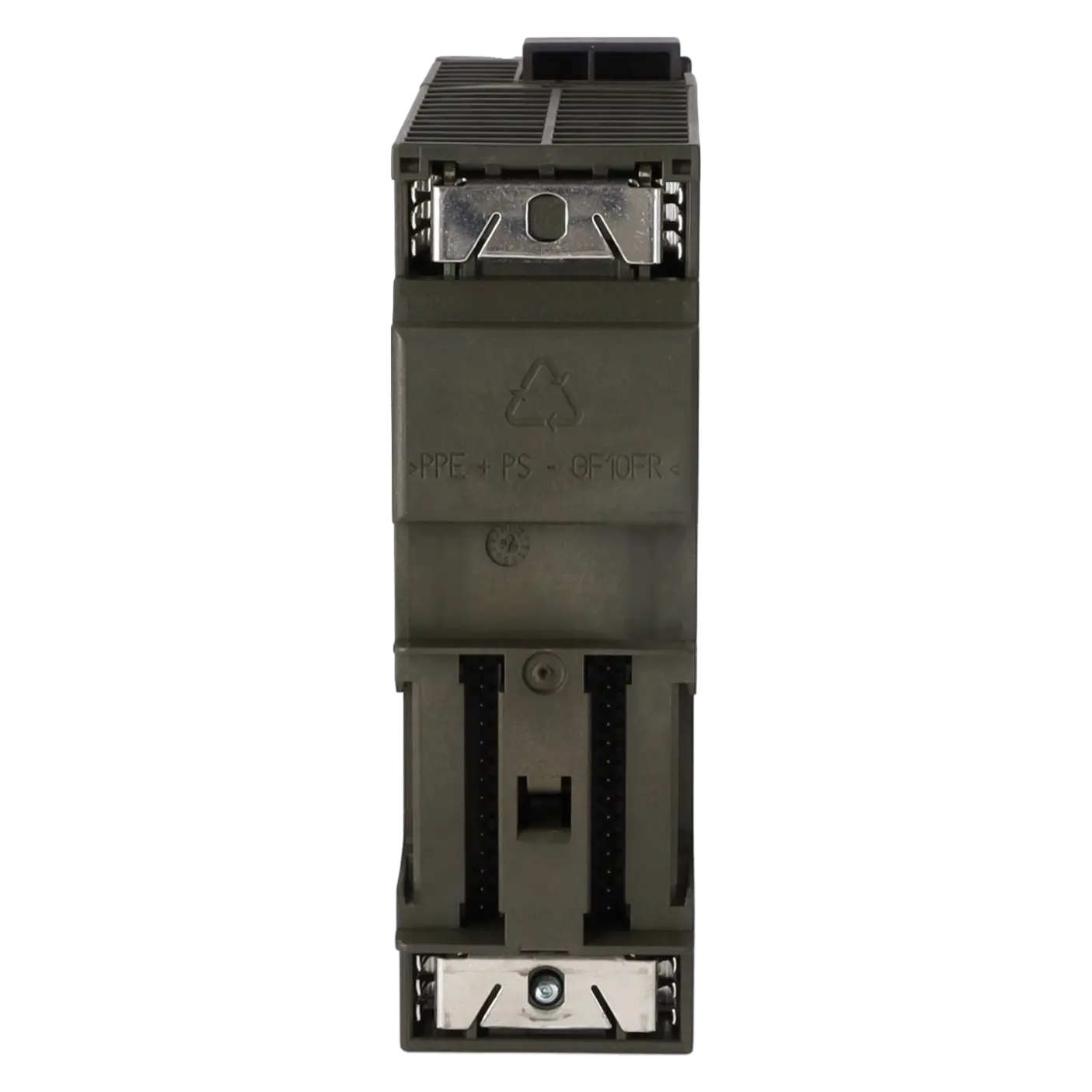
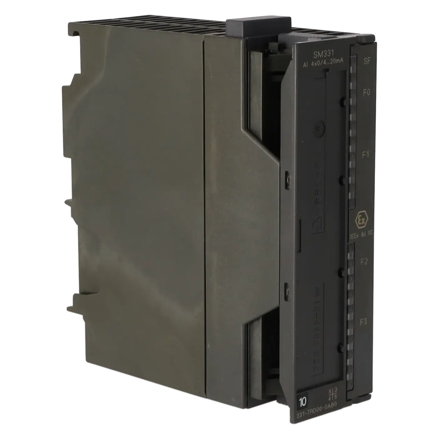
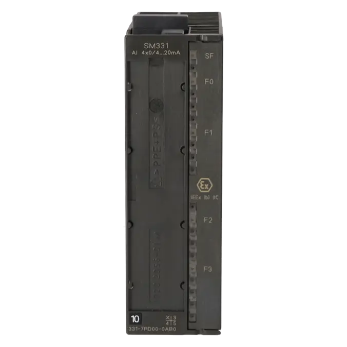
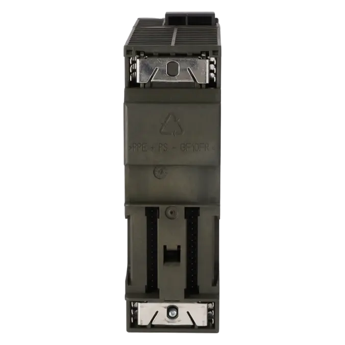
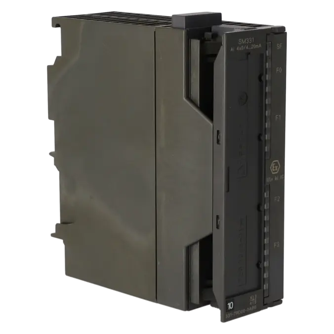
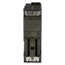
SIMATIC S7, ANALOG INPUT SM 331, ISOLATED, 4 AE; 0/4 TO 20 MA, 1 X 20-POLE, FOR SIGNALS FROM THE HAZARDOUS AREA, DIAGNOSTICS-CAPABLE, PTB TESTED
Services for SIEMENS 6ES7331-7RD00-0AB0
Repair
from 629,85 €
to 926,25 €
Replacement
1.000,35 €
750,26 €
Used
1.111,51 €
833,63 €
New
1.235,00 €
926,25 €
SIEMENS |
6ES7331-7RD00-0AB0 –
additional product information
| Delivery information | |||
|---|---|---|---|
| Export identifier | AL: N ECCN: EAR99H | ||
| Net weight | 0.409 | ||
| Quantity | 1 Stück | ||
| Packaging quantity | 1 | ||
| Additional product information | |||
|---|---|---|---|
| Product status | EOP: 2025-10-01 | ||
| EAN | 4025515061229 | ||
| UPC | 662643230253 | ||
| Static lot number | 85389091 | ||
| List indicator | STPCS7 | ||
| Product group | 4428 | ||
| Country of origin | DE | ||
| Compliance with the substance restrictions according to RoHS directive | Since: 20110321 | ||
| Product classifications | Version | Classification | |
|---|---|---|---|
| eClass | 4 | 27-24-03-05 | |
| eClass | 5.1 | 27-24-22-01 | |
| eClass | 6.0 | 27-24-22-01 | |
| ETIM | 3 | / | |
| ETIM | 4 | EC001420 | |
| ETIM | 5 | EC001420 | |
What is 6ES7331-7RD00-0AB0 and where is it used?
The 6ES7331-7RD00-0AB0 is a SIMATIC S7 SM 331 analogue input module for four current signals in the 0/4 to 20 mA range. The module is galvanically isolated, supports diagnostics, is PTB-certified, and is designed for signals originating from hazardous areas. It is typically used in S7-300 and ET 200M systems where transmitters from process plants must be connected safely to the PLC. Typical applications include measurement points in the chemical, energy, tank storage, process, and manufacturing industries where intrinsically safe field signals are processed. It is important to note that the module itself is installed outside the hazardous area, while intrinsically safe field devices from Zones 1, 2, 21, and 22 may be connected.
Overview of the most important technical data and what they mean
The module operates with a 24 V DC load supply, provides four analogue inputs, and supports both 2-wire and 4-wire transmitters. Current measurement ranges of 0 to 20 mA and 4 to 20 mA are available, each with an input resistance of 50 Ω. The integration time can be parameterised from 2.5 ms to 100 ms. In practice, shorter integration times provide faster response, while longer times improve resolution and noise suppression. Depending on the selected settings, Siemens specifies a resolution of 10 to 15 bits plus sign. The module also offers channel-specific diagnostics, SF and F LEDs, galvanic isolation between channels and the backplane bus, a 20-pin front connector, a maximum ambient temperature of 60 °C, and compact dimensions of 40 × 125 × 120 mm.
Product status, life-cycle status and obsolescence
For purchasing and maintenance departments, the product life cycle is particularly important. Siemens currently lists the 6ES7331-7RD00-0AB0 as a spare part, while the EICHLER product page specifies an EOP (End of Product) date of 01 October 2025. This is a clear indication that active life-cycle management is required. Operators who continue to use this module in existing installations should proactively secure procurement options, repair capability, and spare-part availability. In practice, this means addressing downtime risks before a failure occurs by implementing replacement, repair, or stocking strategies. A verified, Siemens-designated direct successor could not be reliably identified in the available official sources. Especially in hazardous-area applications, any replacement should therefore be evaluated not only for functionality but also for approvals, certifications, and connection compatibility.
Available EICHLER services and when they are relevant in practice
For operators of older S7-300 and ET 200M systems, EICHLER's services are particularly valuable when obsolescence, supply shortages, or an unexpected system failure occur simultaneously. The product page lists repair services with a turnaround time of 2–5 days, exchange units within 1–3 days, as well as used and new modules with short delivery times. According to EICHLER, repairs include technical cleaning, preventive maintenance, comprehensive functional testing, and a minimum 24-month warranty. This is especially useful when a system has been designed specifically around this module and engineering modifications are to be avoided. Exchange units are ideal for time-critical downtime situations, used units support cost-conscious spare-part strategies, and new units are suitable for planned spare-stock programmes within standardised maintenance concepts.
| Attribute | Value |
|---|---|
| Supply voltage | |
| Load voltage L+ | |
| ● Rated value (DC) | 24 V |
| ● Reverse polarity protection | Yes |
| Input current | |
| from load voltage L+ (without load), max. | 250 mA |
| from backplane bus 5 V DC, max. | 60 mA |
| Output voltage | |
| Power supply to the transmitters | |
| ● Rated value (DC) | 13 V; at 22 mA |
| Power loss | |
| Power loss, typ. | 3 W |
| Analog inputs | |
| Number of analog inputs | 4 |
| permissible input current for current input (destruction limit), max. | 40 mA |
| Input ranges | |
| ● Voltage | No |
| ● Current | Yes |
| ● Thermocouple | No |
| ● Resistance thermometer | No |
| ● Resistance | No |
| Input ranges (rated values), currents | |
| ● 0 to 20 mA | Yes |
| — Input resistance (0 to 20 mA) | 50 Ω |
| ● 4 mA to 20 mA | Yes |
| — Input resistance (4 mA to 20 mA) | 50 Ω |
| Cable length | |
| ● shielded, max. | 200 m |
| Analog value generation for the inputs | |
| Integration and conversion time/resolution per channel | |
| ● Resolution with overrange (bit including sign), max. | 16 bit; 10 bit to 15 bit + sign |
| ● Integration time, parameterizable | Yes; 2.5 to 100 ms |
| ● Interference voltage suppression for interference frequency f1 in Hz | 10 to 400 Hz |
| Encoder | |
| Connection of signal encoders | |
| ● for current measurement as 2-wire transducer | Yes |
| ● for current measurement as 4-wire transducer | Yes |
| Errors/accuracies | |
| Operational error limit in overall temperature range | |
| ● Current, relative to input range, (+/-) | 0.45 % |
| Basic error limit (operational limit at 25 °C) | |
| ● Current, relative to input range, (+/-) | 0.1 % |
| Interrupts/diagnostics/status information | |
| Diagnostics function | Yes |
| Diagnoses | |
| ● Diagnostic information readable | Yes |
| ● Overrange | Yes |
| ● Wire-break in signal transmitter cable | Yes |
| ● Short-circuit of the signal encoder cable | Yes |
| Diagnostics indication LED | |
| ● Group error SF (red) | Yes |
| ● Channel fault indicator F (red) | Yes |
| Ex(i) characteristics | |
| Module for Ex(i) protection | Yes |
| maximum values for connecting terminals for gas group IIC | |
| ● Uo (no-load voltage), max. | 25.2 V |
| ● Io (short-circuit current), max. | 68.5 mA |
| ● Po (power output), max. | 431 mW |
| ● Co (permissible external capacity), max. | 90 nF |
| ● Lo (permissible external inductivity), max. | 7.5 mH |
| Potential separation | |
| Potential separation analog inputs | |
| ● between the channels | Yes |
| ● between the channels and backplane bus | Yes |
| Standards, approvals, certificates | |
| Use in hazardous areas | |
| ● ATEX marking | ATEX II 3 G (2) GD Ex nA [ib Gb] [ib IIIC Db] IIC T4 Gc |
| ● FM marking | Class I, Division 2, Group A, B, C, D T4 |
| ● Test number PTB | Ex-96.D.2092X |
| Ambient conditions | |
| Ambient temperature during operation | |
| ● max. | 60 °C |
| Connection method | |
| required front connector | 20-pin |
| Dimensions | |
| Width | 40 mm |
| Height | 125 mm |
| Depth | 120 mm |
| Weights | |
| Weight, approx. | 290 g |
| Fault description | Possible solution |
|---|---|
| Why does the 6ES7331-7RD00-0AB0 report a wire break even though the transmitter is connected? | First check whether the channel is actually parameterised for 4 to 20 mA and whether wire-break diagnostics are enabled. Siemens specifies that this module interprets an input current of I ≤ 3.6 mA as a wire break and only clears the diagnostic once the current rises above 3.8 mA. Therefore, check the loop current, transmitter power supply, cable continuity, terminal wiring, and whether the device is configured as a 2-wire or 4-wire transmitter. |
| Why do I not receive a wire-break diagnostic when using a 0 to 20 mA signal? | This is not a fault in the strict sense but a characteristic of the module. Siemens explicitly states that wire-break detection is not available in the 0 to 20 mA measuring range. If line monitoring is required, the channel must be configured for 4 to 20 mA and diagnostics must be enabled. Afterwards, verify that the connected transmitter supports operation in this mode. |
| Why are the SF and F LEDs lit and no valid analogue values are being received? | Typical causes include incorrect parameter settings, missing parameterisation, or a missing L+ supply voltage. Siemens identifies these as common diagnostic causes. In an SPS forum discussion relating specifically to the 6ES7331-7RD00-0AB0, peripheral access faults were also linked to an incorrectly transferred hardware configuration, incorrect addresses, or mismatched access widths. Therefore, verify the exact MLFB in the hardware configuration, the start address, the transfer to the CPU, and the 24 V DC supply connected to L+ and M. |
| Why does the module indicate overrange conditions or implausible measured values? | The module supports diagnostics for overrange, wire break, and short circuit of the signal cable. Check whether the transmitter is actually operating within the configured measuring range, whether 0 to 20 mA has accidentally been configured instead of 4 to 20 mA, and whether the wiring and load resistor are suitable for the transmitter. For stable readings, the integration time and interference suppression settings should also be selected to suit the application. For highly fluctuating signals, increasing the integration time often improves stability. |
| Why is the scaling in STEP 7 incorrect even though a 4 to 20 mA signal is present? | With Siemens analogue modules, the configured measuring range determines the internal value representation. Siemens notes that the selected range is mapped to the standard STEP 7 value range and that the scaling must therefore match the parameterisation. Check whether the channel has been configured for 0 to 20 mA or 4 to 20 mA, and then verify the settings of your SCALE function block, limit values, and plausibility checks accordingly. |
| Why do Ex-related issues occur after connecting an active transmitter? | Siemens specifies a special requirement for this module: when active transmitters are connected, unused transmitter outputs only meet the intended conditions if terminals 3, 7, 12, and 16 are sealed with plastic plugs, for example M3 × 8 screws. In addition, the power supply for the intrinsically safe circuit must be routed correctly. If this requirement is overlooked, the resulting symptoms may appear to be commissioning problems when in fact they are related to the correct implementation of the hazardous-area installation. |
| Why do the fault LEDs behave unexpectedly or appear implausible? | Siemens has published an official notice concerning this module. On 6ES7331-7RD00-0AB0 units manufactured between May 2015 and April 2016, a malfunction of the fault indication LEDs may occur. If the diagnostic messages do not match the LED indications, then in addition to checking the wiring and parameterisation, the hardware revision and manufacturing date should also be verified. |
Is 6ES7331-7RD00-0AB0 a standard PLC analogue input module or an Ex module?
It is not a standard analogue input module, but an Ex-capable SM 331 analogue input module designed for signals originating from hazardous areas. Siemens classifies the module as suitable for hazardous area signals, PTB tested, and certified with ATEX and FM approvals. For operators, this means the module is specifically intended for connecting intrinsically safe field devices to SIMATIC S7-300 and ET 200M systems. For this reason, any replacement should always be checked not only for electrical compatibility, but also for Ex approvals, connection technology, and project requirements.
Can I connect both 2-wire and 4-wire transmitters?
Yes. Siemens explicitly specifies that the 6ES7331-7RD00-0AB0 supports both 2-wire and 4-wire transmitters. This is particularly important in existing installations where different generations of field devices are often used side by side. Before commissioning, however, you should verify the configured measuring range and determine whether diagnostic functions such as wire-break detection should be enabled. For 4–20 mA signals, diagnostics are generally much more meaningful than for 0–20 mA signals.
Which front connector is required for the 6ES7331-7RD00-0AB0?
This module requires a 20-pin front connector. This is an important consideration during spare-part procurement and service work, as ordering the module alone does not automatically include all connection components. When replacing an existing module, it is advisable to inspect the condition of the installed front connector and confirm that the wiring can be transferred without modification. With Ex-related signals in particular, documenting the terminal assignments before removal is strongly recommended.
Is the product still in the normal Siemens lifecycle or is procurement becoming critical?
The available sources clearly indicate an advanced lifecycle stage. Siemens classifies the module as a spare part, while EICHLER lists an EOP (End of Product) date of 01 October 2025. This does not automatically mean the module is unavailable, but it does mean that availability, repair options, and spare-parts strategy become increasingly important. To avoid unplanned downtime, operators should proactively secure stock levels, repair options, and replacement paths.
Is there a direct Siemens successor for the 6ES7331-7RD00-0AB0?
I could not find a clearly verified direct successor that Siemens explicitly designates for this exact MLFB number in the available official sources. The module is presented as a spare part rather than an actively marketed product with a defined replacement. For maintenance and procurement teams, this is an important consideration: any alternative module must be evaluated not only for electrical compatibility but also for Ex certification, project configuration, terminal assignment, and diagnostic behaviour.
Which procurement option is most suitable in the event of a machine stoppage: repair, exchange, used, or new?
The answer depends on your specific situation. An exchange unit is usually the best choice when production must be restored immediately, as EICHLER currently indicates a lead time of 1–3 days. Repair is appropriate when the original module is to be retained and professionally overhauled; EICHLER specifies 2–5 days, including technical cleaning, preventive maintenance, comprehensive functional testing, and a minimum 24-month warranty. Used units are often attractive for cost-conscious spare-parts strategies, while new units are suitable for planned stockholding. As of 22 May 2026, short delivery times are listed for exchange, used, and new units.
Must the module itself be installed inside the hazardous area?
No. Siemens specifies that the analogue input module must be installed outside the hazardous area in a suitable enclosure providing at least IP20 protection according to EN 60529. At the same time, intrinsically safe devices located in Zones 1 and 2 as well as Zones 21 and 22 may be connected to the module. This distinction is crucial in practice: the field signal may originate in a hazardous area, but the module itself is installed in a safe area. When replacing the module, it is therefore important to assess not only the PLC hardware but also the complete Ex installation, including the enclosure, wiring concept, and applicable approval requirements.