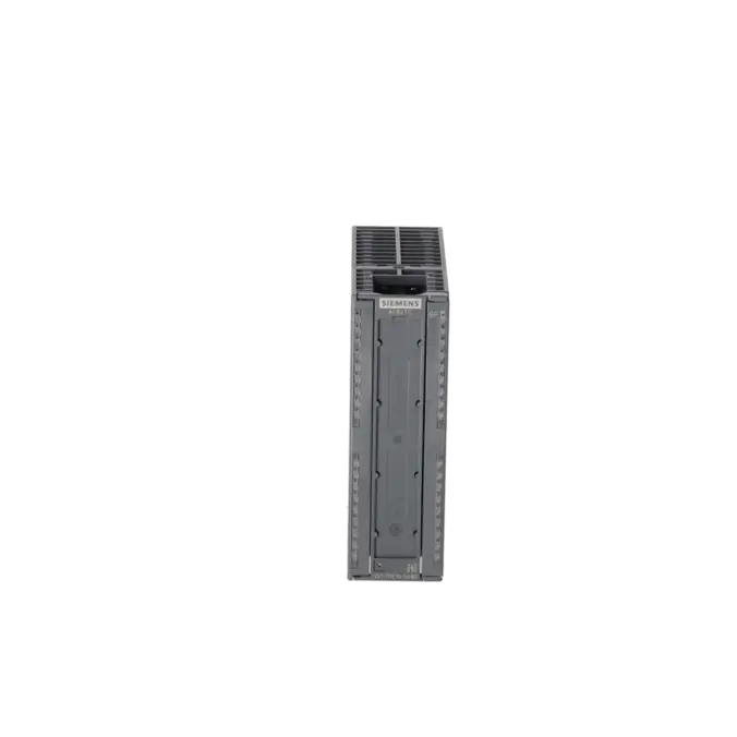
SIEMENS 6ES7331-7PE10-0AB0
-
SIEMENS | PLC Controls | Analog Input / Output Modules
- EICHLER-art.no.: K0252223
- EAN: 4025515077220
- UPC: 040892550382
Product description
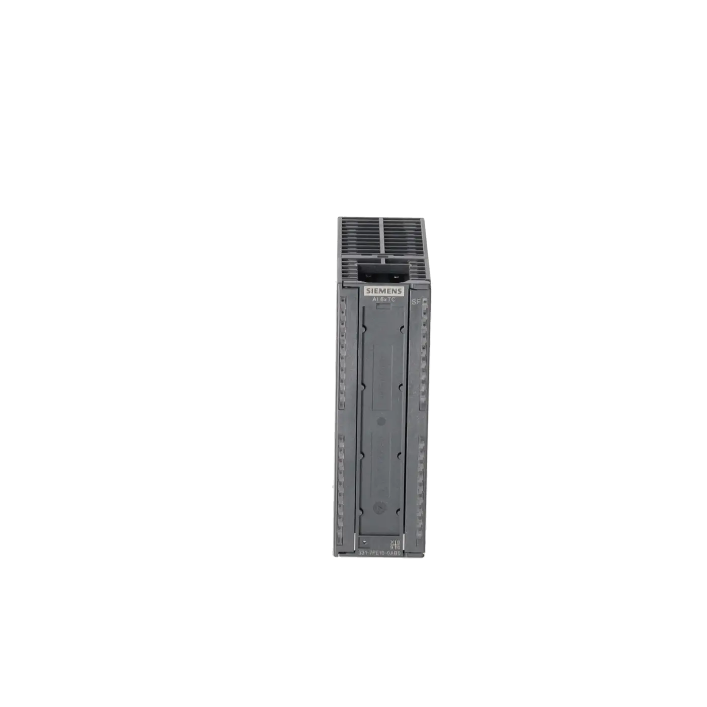
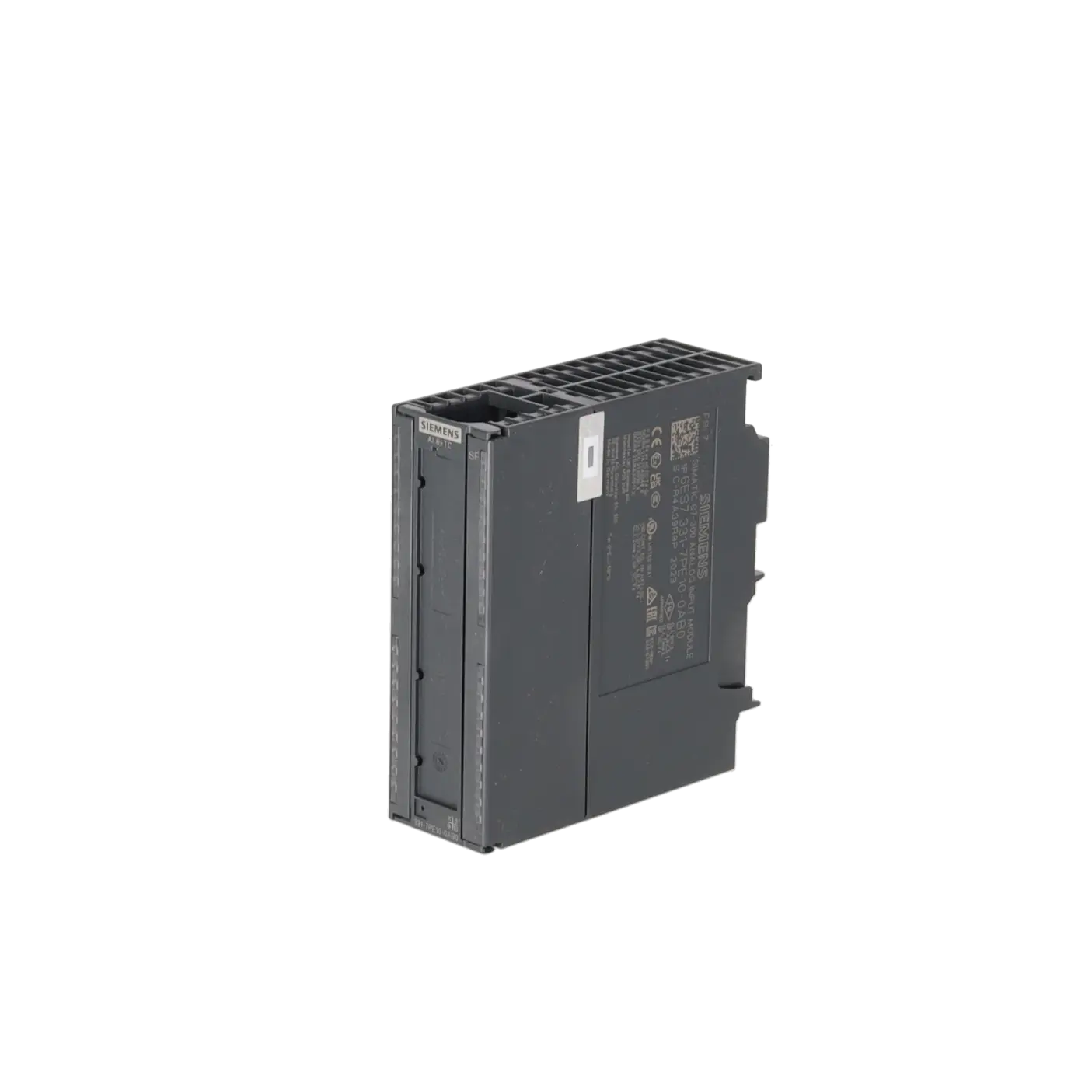
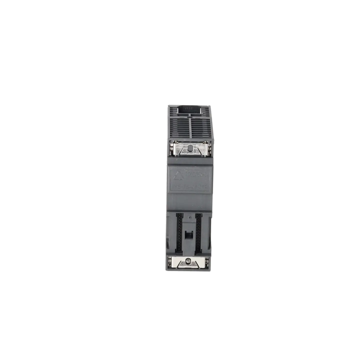
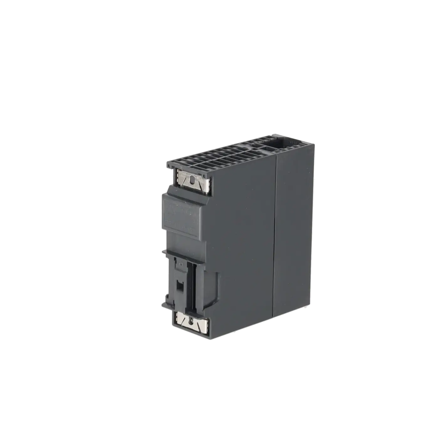
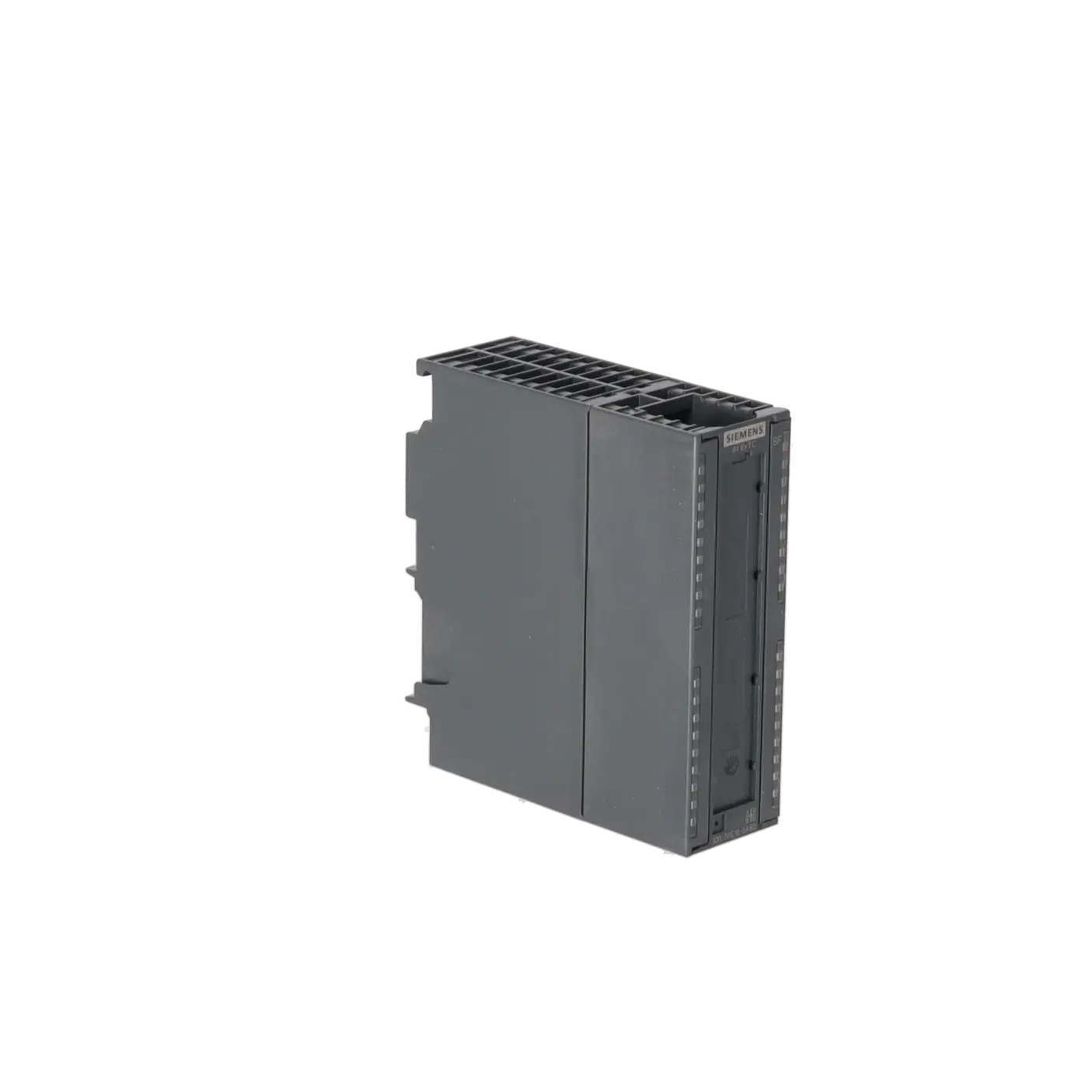
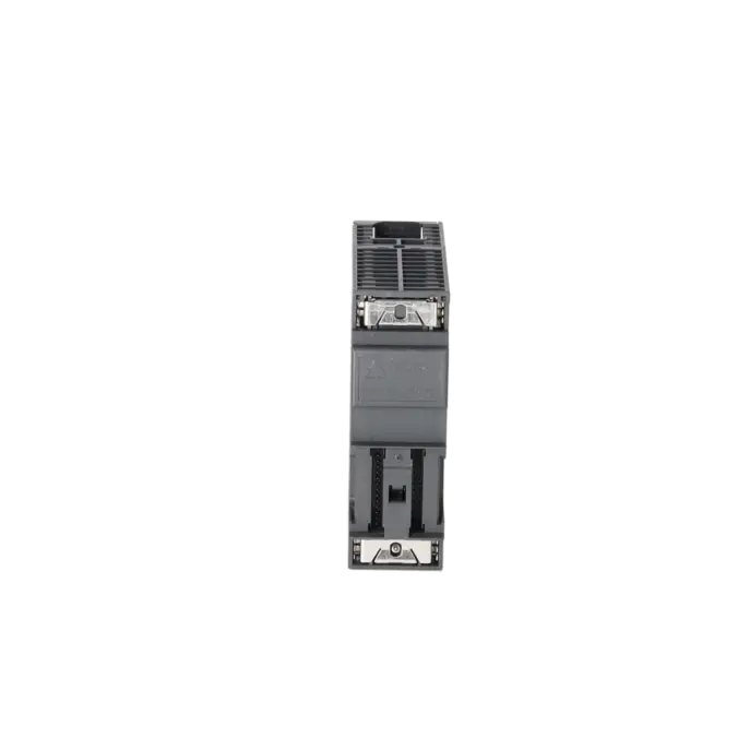
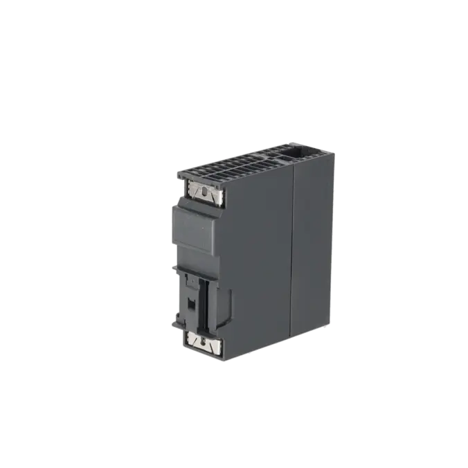
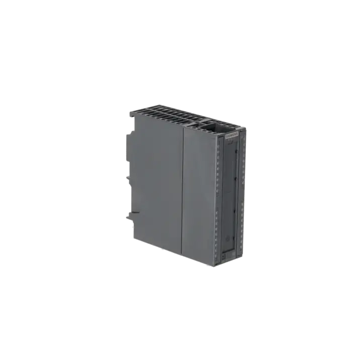
SIMATIC S7-300, ANALOG INPUT SM 331, SINGLE CHANNEL ISOLATED 250 V AC, 6 AI THERMOCOUPLES TYPE B, E, J, K, L, N, R, S, T VOLTAGE: +/-25MV TO +/-1V 16 BIT, 50MS, 1X 40-POLE
Services for SIEMENS 6ES7331-7PE10-0AB0
Repair
from 862,26 €
to 1.268,03 €
Replacement
Used
New
1.690,70 €
1.268,02 €
SIEMENS |
6ES7331-7PE10-0AB0 –
additional product information
| Delivery information | |||
|---|---|---|---|
| Export identifier | AL: N ECCN: EAR99H | ||
| Net weight | 0.33 | ||
| Quantity | 1 Stück | ||
| Packaging quantity | 1 | ||
| Additional product information | |||
|---|---|---|---|
| Product status | |||
| EAN | 4025515077220 | ||
| UPC | 040892550382 | ||
| Static lot number | 85389091 | ||
| List indicator | ST73 | ||
| Product group | 4561 | ||
| Country of origin | DE | ||
| Compliance with the substance restrictions according to RoHS directive | Since: 20081115 | ||
| Product classifications | Version | Classification | |
|---|---|---|---|
| eClass | 4 | 27-24-03-05 | |
| eClass | 5.1 | 27-24-22-01 | |
| eClass | 6.0 | 27-24-22-01 | |
| ETIM | 3 | / | |
| ETIM | 4 | EC001420 | |
| ETIM | 5 | EC001420 | |
What is 6ES7331-7PE10-0AB0 and where is it used?
6ES7331-7PE10-0AB0 is a SIMATIC S7-300 SM 331 analogue input assembly designed for the acquisition of thermocouple signals and low-level voltage signals. The assembly is intended for applications where temperature measurement points must be integrated into a PLC accurately and with high immunity to interference, such as furnaces, heating systems, extruders, drying plants, process engineering applications or ET 200M installations. It provides 6 analogue input channels and features channel-to-channel isolation, which is a significant advantage when measuring distributed signals with different grounding conditions. For maintenance personnel, the module is particularly relevant when troubleshooting temperature measurement faults, sourcing an identical spare part or keeping an existing S7-300 system operational without modifications.
Overview of the key technical data and what they mean
The assembly operates with a 24 V DC load voltage, requires a 40-pin front connector and supports 6 measurement channels. It is compatible with common thermocouple types B, E, J, K, L, N, R, S and T, as well as voltage inputs from ±25 mV to ±1 V. A resolution of 16 bits, or 15 bits plus sign / 0.1 K, provides precise temperature measurement. The basic conversion time is parameterisable at 30 / 50 / 60 / 300 ms, allowing adaptation to local mains frequencies and noise conditions. Additional important features include channel-specific diagnostics, limit value monitoring, hardware interrupts and isolation between channels, the backplane bus and the electronics supply. These features improve diagnostic capability and minimise measurement errors caused by potential differences.
Product status, life-cycle status and obsolescence
Siemens classifies the 6ES7331-7PE10-0AB0 as a spare part in the available product information. This indicates an advanced stage in the product life cycle, where availability, replaceability and repairability become more important than use in new projects. For operators of existing S7-300 installations, this is a clear signal to secure inventory, replacement strategies and service support at an early stage. No clearly defined manufacturer-designated successor for this exact article number could be reliably verified from the available sources. Although the related SM 331 module 6ES7331-7PF11-0AB0 appears in Siemens documentation, it is not explicitly identified as the successor to the 7PE10. In practice, the article number, hardware revision, parameterisation and system compatibility should therefore always be verified carefully before replacement.
Available EICHLER services and when they are relevant in practice
For the 6ES7331-7PE10-0AB0, EICHLER offers repair, exchange, refurbished and new units. Repair is specified with a turnaround time of 2–5 days and includes technical cleaning, preventive maintenance, comprehensive functional testing and a minimum 24-month warranty. This is particularly relevant when the module is to remain in service and rapid recommissioning is more important than migration to a new platform. Exchange and refurbished units are useful when downtime costs are high and an identical replacement is required at short notice. New units are also listed in the shop. For purchasing and production departments, these options provide multiple procurement paths to maintain system availability despite obsolescence risks and minimise unplanned plant downtime. These services are intended exclusively for business customers.
| Attribute | Value |
|---|---|
| General information | |
| Product function | |
| ● Isochronous mode | No |
| Supply voltage | |
| Load voltage L+ | |
| ● Rated value (DC) | 24 V |
| ● Reverse polarity protection | Yes |
| Input current | |
| from load voltage L+ (without load), max. | 150 mA |
| from backplane bus 5 V DC, max. | 100 mA |
| Power loss | |
| Power loss, typ. | 2.2 W |
| Analog inputs | |
| Number of analog inputs | 6 |
| permissible input voltage for voltage input (destruction limit), max. | 35 V; 35 V continuous, 75 V for max. 1 s (mark to space ratio 1:20) |
| Constant measurement current for resistance-type transmitter, typ. | 0.7 mA |
| Input ranges | |
| ● Voltage | Yes |
| ● Current | No |
| ● Thermocouple | Yes |
| ● Resistance thermometer | No |
| ● Resistance | No |
| Input ranges (rated values), voltages | |
| ● 0 to +10 V | No |
| ● 1 V to 5 V | No |
| ● 1 V to 10 V | No |
| ● -1 V to +1 V | Yes |
| — Input resistance (-1 V to +1 V) | 10 MΩ |
| ● -10 V to +10 V | No |
| ● -2.5 V to +2.5 V | No |
| ● -250 mV to +250 mV | Yes |
| — Input resistance (-250 mV to +250 mV) | 10 MΩ |
| ● -5 V to +5 V | No |
| ● -50 mV to +50 mV | Yes |
| — Input resistance (-50 mV to +50 mV) | 10 MΩ |
| ● -500 mV to +500 mV | Yes |
| — Input resistance (-500 mV to +500 mV) | 10 MΩ |
| ● -80 mV to +80 mV | Yes |
| — Input resistance (-80 mV to +80 mV) | 10 MΩ |
| Input ranges (rated values), currents | |
| ● 0 to 20 mA | No |
| ● -10 mA to +10 mA | No |
| ● -20 mA to +20 mA | No |
| ● -3.2 mA to +3.2 mA | No |
| ● 4 mA to 20 mA | No |
| Input ranges (rated values), thermocouples | |
| ● Type B | Yes |
| — Input resistance (Type B) | 10 MΩ |
| ● Type C | Yes |
| — Input resistance (Type C) | 10 MΩ |
| ● Type E | Yes |
| — Input resistance (Type E) | 10 MΩ |
| ● Type J | Yes |
| — Input resistance (type J) | 10 MΩ |
| ● Type K | Yes |
| — Input resistance (Type K) | 10 MΩ |
| ● Type L | Yes |
| — Input resistance (Type L) | 10 MΩ |
| ● Type N | Yes |
| — Input resistance (Type N) | 10 MΩ |
| ● Type R | Yes |
| — Input resistance (Type R) | 10 MΩ |
| ● Type S | Yes |
| — Input resistance (Type S) | 10 MΩ |
| ● Type T | Yes |
| — Input resistance (Type T) | 10 MΩ |
| ● Type U | Yes |
| — Input resistance (Type U) | 10 MΩ |
| ● Type TXK/TXK(L) to GOST | Yes |
| — Input resistance (Type TXK/TXK(L) to GOST) | 10 MΩ |
| Input ranges (rated values), resistance thermometer | |
| ● Cu 10 | No |
| ● Ni 100 | No |
| ● Ni 1000 | No |
| ● LG-Ni 1000 | No |
| ● Ni 120 | No |
| ● Ni 200 | No |
| ● Ni 500 | No |
| ● Pt 100 | No |
| ● Pt 1000 | No |
| ● Pt 200 | No |
| ● Pt 500 | No |
| Input ranges (rated values), resistors | |
| ● 0 to 150 ohms | No |
| ● 0 to 300 ohms | No |
| ● 0 to 600 ohms | No |
| ● 0 to 6000 ohms | No |
| Thermocouple (TC) | |
| Temperature compensation | |
| — parameterizable | Yes |
| — internal temperature compensation | Yes |
| — external temperature compensation with Pt100 | Yes |
| — external temperature compensation with compensations socket | Yes |
| — for definable comparison point temperature | Yes |
| Characteristic linearization | |
| ● parameterizable | Yes |
| — for thermocouples | Type B, E, J, K, L, N, R, S. T, U, C, TXK, XK(L) |
| — for resistance thermometer | No |
| Cable length | |
| ● shielded, max. | 200 m |
| Analog value generation for the inputs | |
| Integration and conversion time/resolution per channel | |
| ● Resolution with overrange (bit including sign), max. | 16 bit; Two's complement |
| ● Integration time, parameterizable | Yes |
| ● Basic conversion time (ms) | 30 / 50 / 60 / 300 ms |
| ● Integration time (ms) | 10/ 16.67/ 20/ 100 ms |
| ● Interference voltage suppression for interference frequency f1 in Hz | 10 / 50 / 60 / 400 Hz |
| Encoder | |
| Connection of signal encoders | |
| ● for voltage measurement | Yes |
| Errors/accuracies | |
| Operational error limit in overall temperature range | |
| ● Voltage, relative to input range, (+/-) | Operating error at 0 ... 60 °C: ±0.12% @ ±25 mV, ±0.08% @ ±50 mV, ±0.6% @ ±80 mV, ±0.05% @ ±250 mV, ±0.05% @ 500 mV, ±0.05% @ ±1 V |
| ● Thermocouple, relative to input range, (+/-) | See manual for details |
| Basic error limit (operational limit at 25 °C) | |
| ● Voltage, relative to input range, (+/-) | See manual for details |
| ● Thermocouple, relative to input range, (+/-) | See manual for details |
| Interrupts/diagnostics/status information | |
| Diagnostics function | Yes; Parameterizable |
| Alarms | |
| ● Diagnostic alarm | Yes; channel by channel |
| ● Limit value alarm | Yes; Parameterizable |
| ● Hardware interrupt | Yes; Parameterizable |
| Diagnoses | |
| ● Diagnostic information readable | Yes |
| Diagnostics indication LED | |
| ● Group error SF (red) | Yes |
| Potential separation | |
| Potential separation analog inputs | |
| ● between the channels | Yes |
| ● between the channels, in groups of | 1 |
| ● between the channels and backplane bus | Yes |
| ● between the channels and the power supply of the electronics | Yes |
| Isolation | |
| Isolation tested with | 2 500 V DC |
| Connection method | |
| required front connector | 40-pin |
| Dimensions | |
| Width | 40 mm |
| Height | 125 mm |
| Depth | 120 mm |
| Weights | |
| Weight, approx. | 272 g |
| Fault description | Possible solution |
|---|---|
| Why does the 6ES7331-7PE10-0AB0 display incorrect temperatures? | First check the configured thermocouple type, the selected cold-junction compensation method and the compensation cable being used. Siemens points out that thermocouples always measure temperature differences and therefore require the reference junction to be correctly taken into account. If extensions are made using unsuitable cable types or if the cold-junction compensation is configured incorrectly, systematic measurement deviations will occur. Typical troubleshooting cases show temperature errors of around 20°C when compensation settings and the actual installation do not match. |
| Why does the module provide negative, fluctuating or implausible values? | Check the polarity of the thermocouple and ensure EMC-compliant wiring. Siemens explicitly states that incorrect polarity can result in significant measurement errors. In electrically noisy environments, potential differences between M and MANA or improper shield grounding can also cause unstable readings. If measured values drift as the control cabinet temperature increases, the cause is often the location of the reference junction or thermally unfavourable wiring arrangements. |
| Why is the SF LED lit on the 6ES7331-7PE10-0AB0 or why is OB82 triggered? | The SF LED indicates that the module has reported a diagnostic event. Siemens lists possible causes including configuration or parameterisation errors, common-mode faults, wire breaks, underrange conditions and overrange conditions. If the diagnostic interrupt is enabled, OB82 will be called. For troubleshooting, read the diagnostic buffer, inspect the channel wiring, verify the 24 V L+ supply and ensure that the measurement type and measurement range have been parameterised correctly. |
| Why does the input always show 32767 or 7FFFH? | Siemens describes 7FFFH as the response of analogue input modules to faults, overrange conditions or disabled channels. In practice, this usually indicates an incorrect measurement range, a parameterisation error, an open channel, a common-mode fault or a wiring issue. If several channels suddenly jump to the maximum value after connecting an additional signal, the shared wiring, reference potential and channel assignment should be examined particularly carefully. |
| Why is the temperature value incorrect after processing in STEP 7? | In thermocouple applications, the error is often not caused by the module itself but by subsequent data processing. In practical cases, FC105 SCALE is frequently used incorrectly even though the thermocouple value is already supplied in a suitably scaled format and only needs to be interpreted correctly. Therefore, check the raw value representation, data type conversion and configured temperature units before assuming that the module is defective. |
Which thermocouple types are supported by 6ES7331-7PE10-0AB0?
The module is designed to acquire a wide range of thermocouple types and is specified in the product data for the common types B, E, J, K, L, N, R, S and T. Detailed Siemens documentation also lists additional supported variants within the module context. For purchasing and maintenance personnel, it is essential that the sensor type and channel parameterisation match exactly. Even an incorrect thermocouple selection can result in temperature values that appear plausible but are actually incorrect. Before ordering or replacing the module, not only the part number but also the thermocouple technology used in the machine should therefore be verified.
Can 6ES7331-7PE10-0AB0 also be used in an ET 200M system?
Yes. Siemens specifies suitable IM 153 interface modules for distributed operation in ET 200M and also defines requirements regarding firmware and STEP 7 versions. This is particularly important when the goal is not only to replace a faulty module but also to continue operating an existing ET 200M station without modifications. Before procurement, it should therefore be verified which IM 153 version is installed, whether the software version is compatible and whether the existing project can continue to be used without changes. This helps prevent situations where a mechanically compatible module is installed but the system cannot start correctly due to configuration or compatibility limitations.
Is 6ES7331-7PE10-0AB0 still in the active product life cycle or only available as a spare part?
The available Siemens sources classify the module as a spare part. This does not automatically mean that the module is no longer available, but it does indicate that long-term supply is increasingly dependent on spare-part management, repair services and replacement procurement. For this reason, identical part numbers, inventory planning and reliable service options are particularly important for S7-300 modules. Operators seeking to reduce production risks should treat this module as a critical installed-base component and should not wait until a complete failure occurs before planning procurement.
Do I need a 40-pin front connector for 6ES7331-7PE10-0AB0?
Yes. The technical specifications state that the module requires a 40-pin front connector. This is important during procurement because a missing or incorrect connector can delay commissioning even when the module itself is already available. During maintenance and replacement activities, it should therefore always be verified whether the existing connector, labelling, terminal assignment and wiring can be reused or whether a complete ready-to-install replacement assembly is required.
Can the module monitor limit values and send diagnostic information to the CPU?
Yes. Siemens specifies programmable diagnostics, diagnostic interrupts, limit value monitoring for all 6 channels and hardware interrupts triggered by limit value violations. This is useful for operators who want to do more than simply display temperature values and instead handle abnormal conditions directly within the PLC program. When these functions are configured correctly, critical temperature events can be detected more quickly, alarms can be generated in a targeted manner and fault sources can be identified more easily on a per-channel basis. In process-critical applications, this represents a significant advantage compared with simple temperature monitoring without diagnostic functionality.
Is repair, replacement or purchasing a new unit the best option for 6ES7331-7PE10-0AB0?
The best option depends on the required response time and the overall plant strategy. Repair is often the preferred choice when the existing module is to remain in the original system and a technically verified restoration is more economical. Exchange units or refurbished modules are attractive when downtime costs are high and an identical replacement is needed quickly. New units are often preferred when an immediately available, unused module is required. EICHLER lists all of these procurement options for this module, including repair turnaround times and new-stock availability. Ultimately, the most suitable solution is the one that minimises downtime while maintaining an acceptable level of technical and commercial risk.