

SIEMENS 6ES7331-7NF00-0AB0
-
SIEMENS | PLC Controls | Analog Input / Output Modules
- EICHLER-art.no.: K0118576
- EAN: 4025515061212
- UPC: 662643177923
Product description
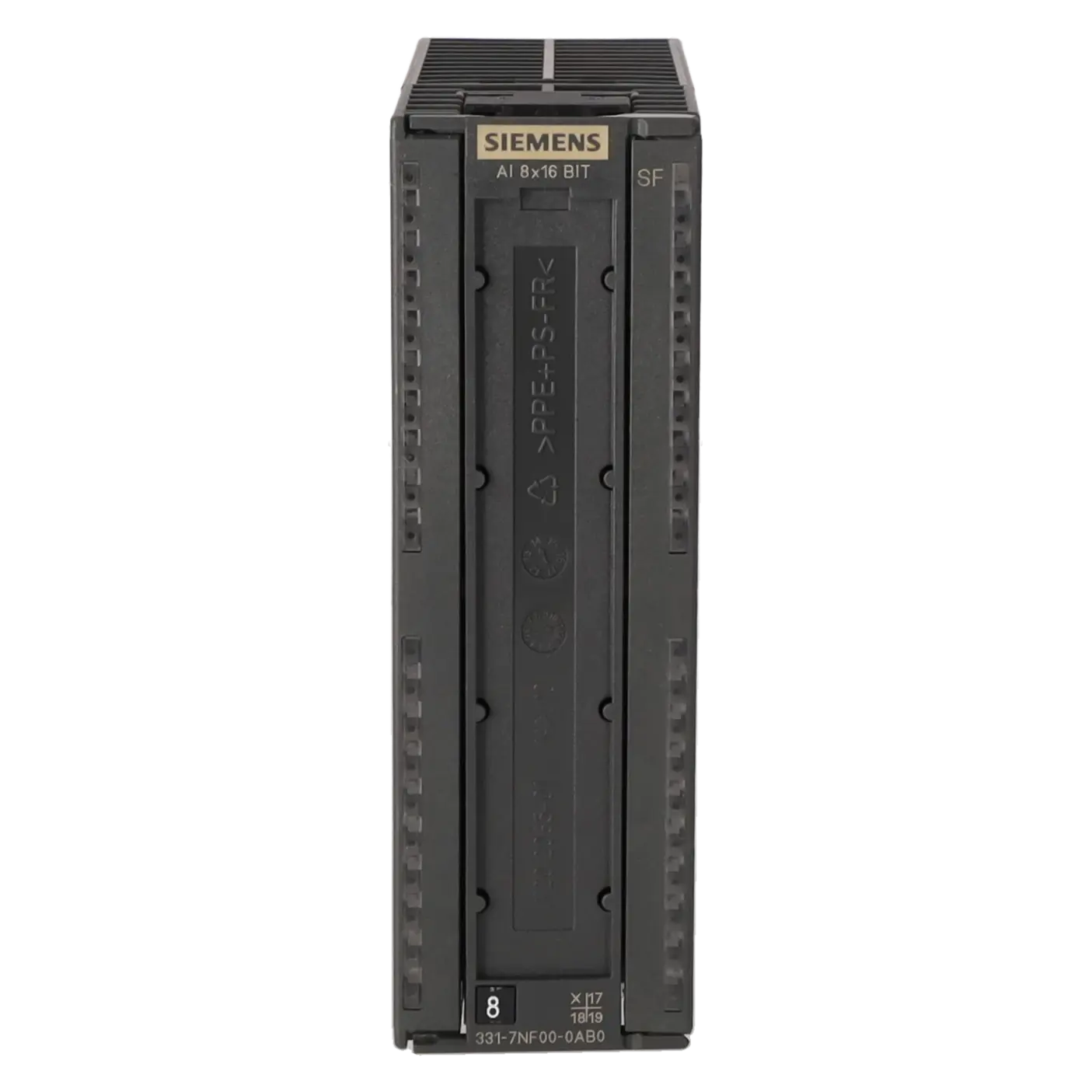
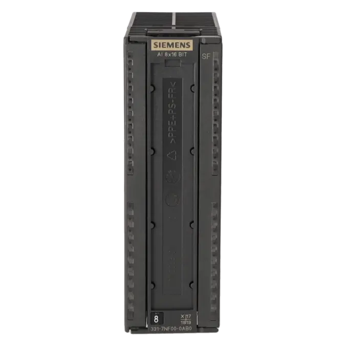
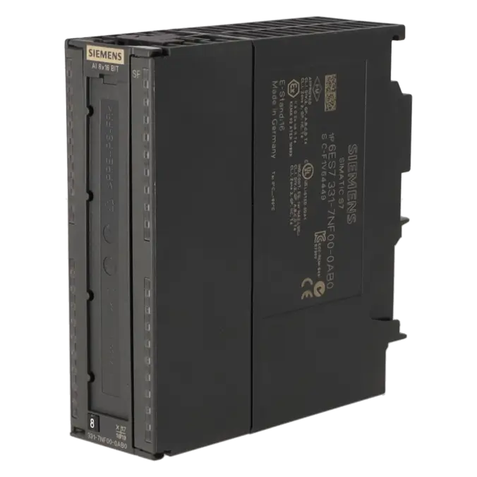
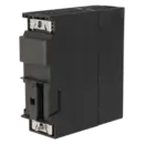
SIMATIC S7-300, ANALOG INPUT SM 331, ISOLATED, 8 AI; +/-5/10V, 1-5 V, +/-20 MA, 0/4 TO 20 MA, 16 BIT (55MS), SINGLE ROOTING (50 V COM.), 1X 40-POLE
Services for SIEMENS 6ES7331-7NF00-0AB0
Repair
from 399,38 €
to 718,88 €
Replacement
882,09 €
661,57 €
Used
980,11 €
735,08 €
New
1.089,00 €
816,75 €
SIEMENS |
6ES7331-7NF00-0AB0 –
additional product information
| Delivery information | |||
|---|---|---|---|
| Export identifier | AL: N ECCN: EAR99H | ||
| Net weight | 0.311 | ||
| Quantity | 1 Stück | ||
| Packaging quantity | 1 | ||
| Additional product information | |||
|---|---|---|---|
| Product status | EOP: 2025-10-01 | ||
| EAN | 4025515061212 | ||
| UPC | 662643177923 | ||
| Static lot number | 85389091 | ||
| List indicator | ST73 | ||
| Product group | 4561 | ||
| Country of origin | DE | ||
| Compliance with the substance restrictions according to RoHS directive | Since: 20080331 | ||
| Product classifications | Version | Classification | |
|---|---|---|---|
| eClass | 4 | 27-24-03-05 | |
| eClass | 5.1 | 27-24-22-01 | |
| eClass | 6.0 | 27-24-22-01 | |
| ETIM | 3 | / | |
| ETIM | 4 | EC001420 | |
| ETIM | 5 | EC001420 | |
What is 6ES7331-7NF00-0AB0 and where is it used?
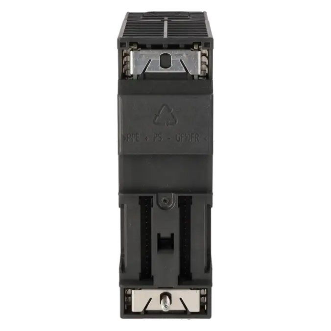
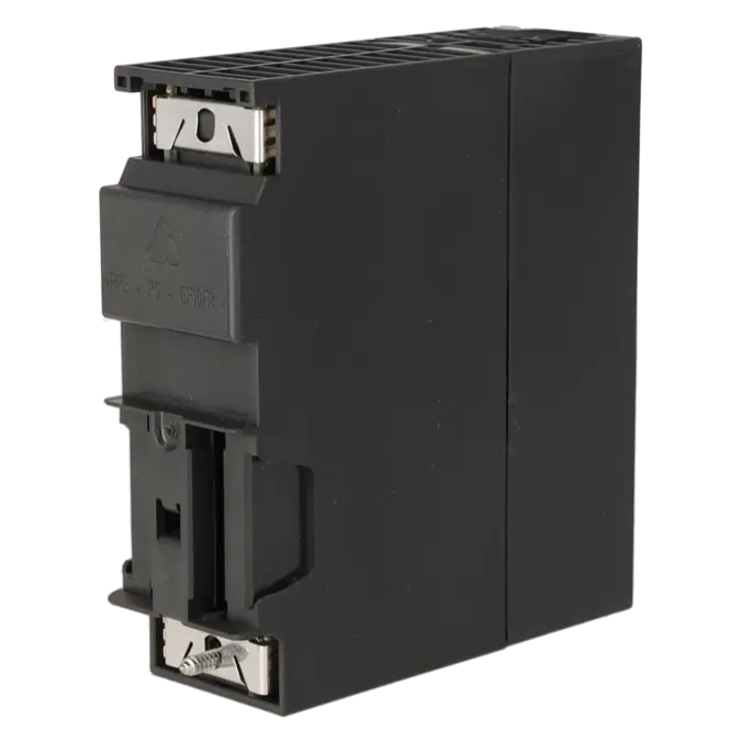
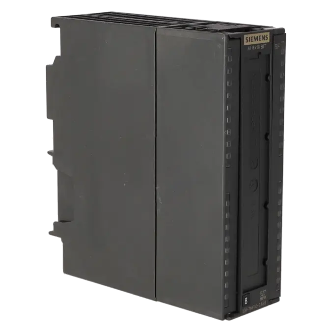
The 6ES7331-7NF00-0AB0 is a SIMATIC S7-300 SM 331 analogue input module from Siemens. The module acquires eight analogue signals and processes typical industrial measurement ranges such as ±10 V, ±5 V, 1 to 5 V, 0 to 20 mA, 4 to 20 mA, and ±20 mA. This makes it suitable for connecting transmitters, sensors, and process signals, for example in pressure, level, flow, or general analogue measurement applications within existing installations. Thanks to its electrical isolation from the backplane bus and 16-bit resolution, the module is particularly attractive where reliable signal acquisition, transparent diagnostics, and the continued operation of existing S7-300 applications are important.
Overview of the key technical data and what it means
The module provides 8 analogue inputs, organised into four channel groups of two channels each. Measurement type, diagnostics, and filtering are therefore configured on a per-group basis. It supports voltage and current measurements, but does not support resistance, RTD, or thermocouple inputs. The 16-bit resolution provides fine raw-value representation, while the specified 55 ms conversion time is intended for stable process measurements rather than high-speed data acquisition. Important practical specifications for control cabinet design include a maximum backplane bus current consumption of 130 mA, a typical power loss of 0.6 W, shielded cable lengths up to 200 m, and a permissible potential difference of 35 V AC or 50 V DC between the inputs.
Product status, life-cycle status, and obsolescence
Siemens officially classifies the 6ES7331-7NF00-0AB0 as a spare part. Its lifecycle status is PLM PM410: Product cancellation, effective 01 October 2025. The EICHLER product page also lists the module with EOP: 2025-10-01. For operators of older S7-300 systems, this is a clear indication that spare-parts strategy and obsolescence management should be addressed proactively. Siemens identifies 6ES7531-7NF10-0AB0 and 6ES7531-7NF00-0AB0 as migration options when moving to S7-1500. For ET 200SP HA, Siemens references 6DL1134-6AF00-0PH1, depending on the measurement function. These references should be regarded as migration paths rather than plug-compatible 1:1 replacements.
Available EICHLER services and when they are relevant
For 6ES7331-7NF00-0AB0, EICHLER offers repair, exchange, used units, new units, and an optional test report for analogue inputs/outputs. Repair is particularly useful when an existing module with known parameterisation and wiring is to remain in service and unplanned software modifications or system changes are to be avoided. According to EICHLER, the repair service includes technical cleaning, preventive maintenance, comprehensive functional testing, and a minimum 24-month warranty. Exchange is the preferred option when downtime is critical. Used and new units help mitigate obsolescence risks within spare-parts inventories and procurement strategies. The optional test report is especially valuable when analogue signal quality must be documented and the recommissioning process needs to be fully traceable.
| Attribute | Value |
|---|---|
| General information | |
| Product function | |
| ● Isochronous mode | No |
| Input current | |
| from backplane bus 5 V DC, max. | 130 mA |
| Power loss | |
| Power loss, typ. | 0.6 W |
| Analog inputs | |
| Number of analog inputs | 8 |
| permissible input voltage for voltage input (destruction limit), max. | 50 V; Permanent |
| permissible input current for current input (destruction limit), max. | 32 mA |
| Input ranges | |
| ● Voltage | Yes |
| ● Current | Yes |
| ● Thermocouple | No |
| ● Resistance thermometer | No |
| ● Resistance | No |
| Input ranges (rated values), voltages | |
| ● 0 to +10 V | No |
| ● 1 V to 5 V | Yes |
| — Input resistance (1 V to 5 V) | 2 MΩ |
| ● 1 V to 10 V | No |
| ● -1 V to +1 V | No |
| ● -10 V to +10 V | Yes |
| — Input resistance (-10 V to +10 V) | 2 MΩ |
| ● -2.5 V to +2.5 V | No |
| ● -250 mV to +250 mV | No |
| ● -5 V to +5 V | Yes |
| — Input resistance (-5 V to +5 V) | 2 MΩ |
| ● -50 mV to +50 mV | No |
| ● -500 mV to +500 mV | No |
| ● -80 mV to +80 mV | No |
| Input ranges (rated values), currents | |
| ● 0 to 20 mA | Yes |
| — Input resistance (0 to 20 mA) | 250 Ω |
| ● -10 mA to +10 mA | No |
| ● -20 mA to +20 mA | Yes |
| — Input resistance (-20 mA to +20 mA) | 250 Ω |
| ● -3.2 mA to +3.2 mA | No |
| ● 4 mA to 20 mA | Yes |
| — Input resistance (4 mA to 20 mA) | 250 Ω |
| Input ranges (rated values), thermocouples | |
| ● Type B | No |
| ● Type C | No |
| ● Type E | No |
| ● Type J | No |
| ● Type K | No |
| ● Type L | No |
| ● Type N | No |
| ● Type R | No |
| ● Type S | No |
| ● Type T | No |
| ● Type U | No |
| ● Type TXK/TXK(L) to GOST | No |
| Input ranges (rated values), resistance thermometer | |
| ● Cu 10 | No |
| ● Ni 100 | No |
| ● Ni 1000 | No |
| ● LG-Ni 1000 | No |
| ● Ni 120 | No |
| ● Ni 200 | No |
| ● Ni 500 | No |
| ● Pt 100 | No |
| ● Pt 1000 | No |
| ● Pt 200 | No |
| ● Pt 500 | No |
| Input ranges (rated values), resistors | |
| ● 0 to 150 ohms | No |
| ● 0 to 300 ohms | No |
| ● 0 to 600 ohms | No |
| ● 0 to 6000 ohms | No |
| Cable length | |
| ● shielded, max. | 200 m |
| Analog value generation for the inputs | |
| Integration and conversion time/resolution per channel | |
| ● Resolution with overrange (bit including sign), max. | 16 bit; Unipolar: 15/15/15/15 bit; bipolar: 15 bit + sign/15 bit + sign/15 bit + sign/15 bit + sign |
| ● Integration time, parameterizable | Yes; 10/ 16.67/ 20/ 100 ms |
| ● Interference voltage suppression for interference frequency f1 in Hz | 400 / 60 / 50 / 10 Hz |
| Encoder | |
| Connection of signal encoders | |
| ● for voltage measurement | Yes |
| ● for current measurement as 2-wire transducer | Yes; with external transmitter; possible with separate supply for transmitter |
| ● for current measurement as 4-wire transducer | Yes |
| Errors/accuracies | |
| Operational error limit in overall temperature range | |
| ● Voltage, relative to input range, (+/-) | 0.1 %; At Ucm = 0 V or ±0.7 % at Ucm = 50 V |
| ● Current, relative to input range, (+/-) | 0.3 %; At Ucm = 0 V or ±0.9 % at Ucm = 50 V |
| Basic error limit (operational limit at 25 °C) | |
| ● Voltage, relative to input range, (+/-) | 0.05 % |
| ● Current, relative to input range, (+/-) | 0.05 % |
| Interrupts/diagnostics/status information | |
| Diagnostics function | Yes; Parameterizable |
| Alarms | |
| ● Diagnostic alarm | Yes; Parameterizable |
| ● Limit value alarm | Yes; Parameterizable, channels 0 and 2 |
| Diagnoses | |
| ● Diagnostic information readable | Yes |
| Diagnostics indication LED | |
| ● Group error SF (red) | Yes |
| Potential separation | |
| Potential separation analog inputs | |
| ● between the channels | No |
| ● between the channels, in groups of | 2 |
| ● between the channels and backplane bus | Yes |
| Isolation | |
| Isolation tested with | 500 V DC |
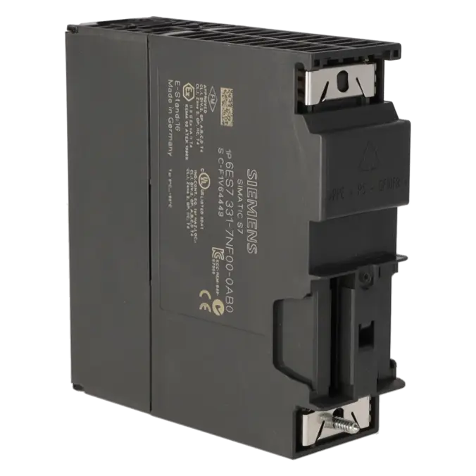
| Connection method | |
| required front connector | 40-pin |
| Dimensions | |
| Width | 40 mm |
| Height | 125 mm |
| Depth | 117 mm |
| Weights | |
| Weight, approx. | 272 g |
| Fault description | Possible solution |
|---|---|
| Why does the 6ES7331-7NF00-0AB0 return 0 or implausible values with a 4–20 mA transmitter? | First check the parameterisation of the channel group. Without parameterisation, the module operates by default as a ±10 V voltage input. For current signals, the correct measurement type must be configured, and with 4–20 mA, the transmitter must be wired correctly in the current loop. In practice, zero values or incorrect readings are often caused by the wrong measurement type, incorrect series wiring, or missing raw-value scaling in the user program. |
| Why does the SM 331 report wire break or SF, even though the sensor is connected? | Wire-break monitoring on this module is relevant for 1 to 5 V and 4 to 20 mA. When wire-break monitoring is enabled, a wire break is diagnosed below 3.6 mA or 0.9 V. Signals close to the limit, voltage drops in the loop, loose terminals, or incorrectly configured diagnostics can therefore trigger an SF message. Check the supply, terminals, loop current, and the evaluation of the diagnostic bytes or OB82. |
| Why does the value 27648 appear in the PIW/IW instead of directly showing 20 mA or 10 V? | The module provides raw values in the process image, not finished engineering units. In S7-300 analogue modules, 27648 represents the end of the nominal range, for example +10 V in the ±10 V range. Current ranges are also processed internally as raw values. The input values must therefore be converted into physical units in the user program using normalisation or scaling blocks. |
| Why do I receive 7FFFH/32767 or 8000H/-32768 at the analogue input? | These values are typical indicators of overrange or underrange. They occur when the input signal is outside the configured range, when the wiring or polarity is incorrect, or when the measurement range and transmitter do not match. If diagnostics are enabled, an additional entry is created in the diagnostic buffer. Therefore, check the measurement range, limit values, wiring, and transmitter output together rather than relying only on the PLC value. |
| Why does a used channel behave unstably when the second channel in the same group remains unused? | The eight inputs are organised into four channel groups. If a configured input remains unused, it must be handled correctly depending on the measurement range: for 1 to 5 V, it should be connected in parallel with the used input; for 4 to 20 mA, it should be connected in series with the current measuring resistor; in other measurement ranges, the positive and negative inputs should be short-circuited. Otherwise, diagnostics and measured-value processing of the used channel may become faulty. |
Is 6ES7331-7NF00-0AB0 still available or only as a spare part?
Siemens classifies the module as a Spare Part and marks it with Product Cancellation effective 01 October 2025. For operators, this means that the module is no longer an active standard product but rather a component for existing installations with an increased obsolescence risk. At the same time, EICHLER offers several procurement and service options specifically for this situation, including repair, exchange, used units, and new units. This helps maintain supply availability even when direct manufacturer sourcing is no longer the primary option.
Which Siemens successor is suitable for 6ES7331-7NF00-0AB0?
Siemens does not specify a plug-compatible 1:1 replacement for this module. In official migration documentation, Siemens refers to 6ES7531-7NF10-0AB0 and 6ES7531-7NF00-0AB0 when migrating to S7-1500. For ET 200SP HA, Siemens identifies 6DL1134-6AF00-0PH1, depending on the measurement function. It is important to note that these modules are migration targets rather than direct drop-in replacements. Before upgrading, the measurement type, channel grouping, wiring, and project configuration should always be reviewed together.
Can 6ES7331-7NF00-0AB0 be reparameterised while the CPU is in RUN?
Yes. According to Siemens, reparameterisation during RUN mode is possible. This is particularly useful when measurement types, limit values, or diagnostic functions need to be modified in a running installation. It is also important to remember that, without parameterisation, the module defaults to voltage measurement with a ±10 V range. When current transmitters are used, the parameter settings should therefore be checked carefully before evaluating or scaling measured values.
How are the module’s eight inputs organised?
The eight inputs are divided into four channel groups with two channels each. This is important in practice because parameters such as measurement type, measuring range, diagnostics, and interference-frequency suppression are configured on a group basis rather than individually for each channel. As a result, mixing different sensor types or signal types within the same channel group can quickly lead to limitations. This grouping should always be considered during troubleshooting, replacement projects, and system modifications.
When is repair more sensible than exchange or purchasing a replacement unit?
Repair is usually the best option when the existing module is already fully integrated into the system and changes to wiring, parameterisation, or approval procedures should be avoided. Exchange is the preferred choice when downtime costs are the main concern and the module must be replaced as quickly as possible. New or used units can be attractive when building spare-parts inventory, maintaining standardisation, or securing long-term availability. With a discontinued product, this distinction becomes particularly important because every installation has different requirements regarding time pressure, budget, and approval processes.
Why is a test report particularly valuable for analogue modules?
For analogue input modules, a simple functional test is often not sufficient because the critical factor is not only whether a signal is present, but also the signal quality, measuring range accuracy, and reliable reintegration into the system. The analogue input/output test report offered on the product page is therefore especially valuable for applications with documentation requirements, quality assurance standards, audit obligations, or sensitive measurement chains. For maintenance and procurement teams, it provides greater confidence during recommissioning, acceptance testing, and internal approval processes.