| General information |
|
| Product type designation |
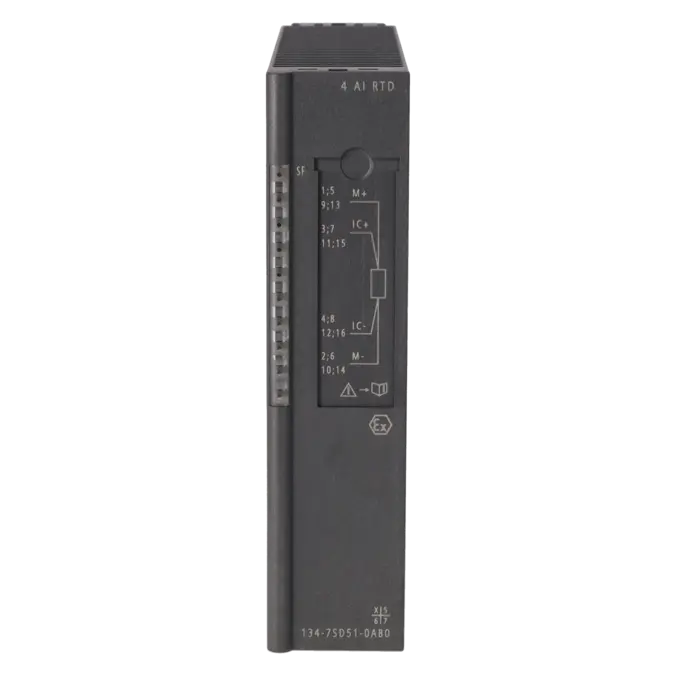
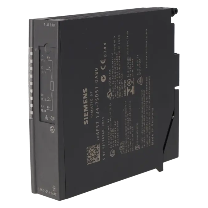
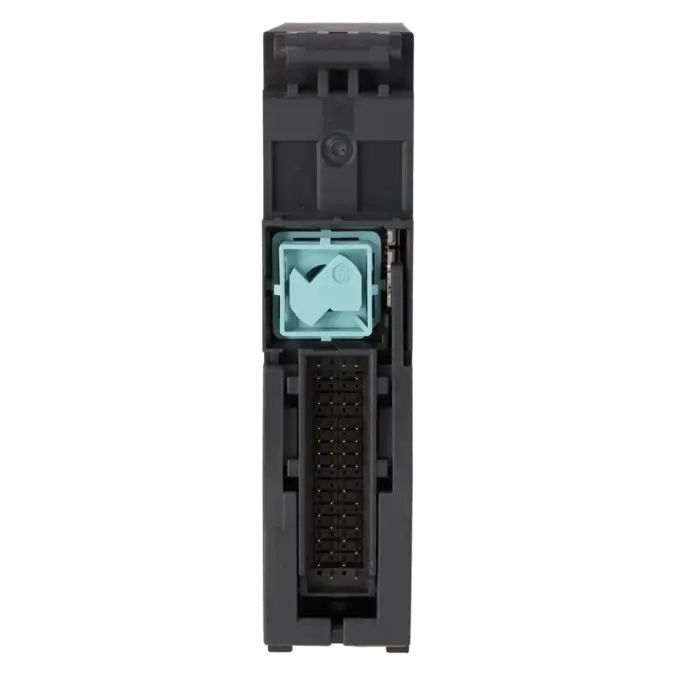
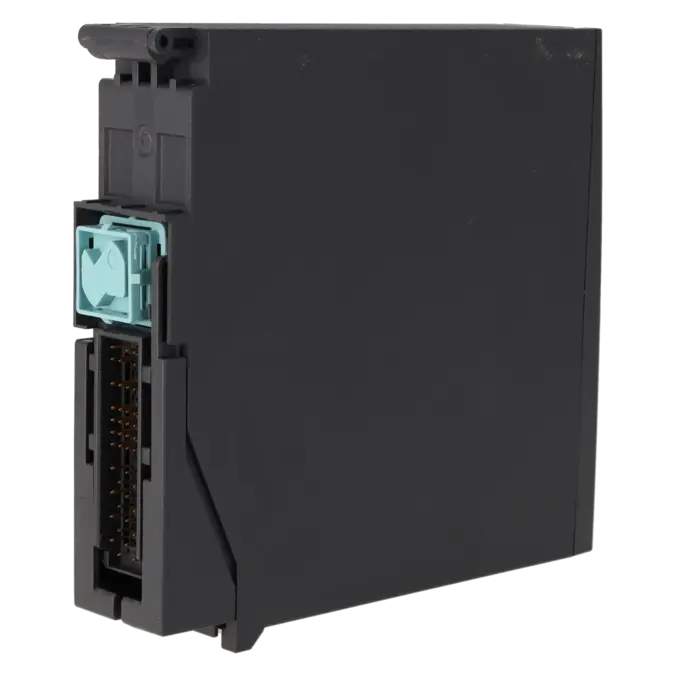
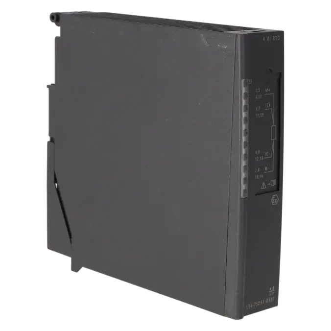
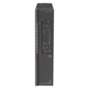
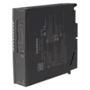
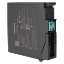
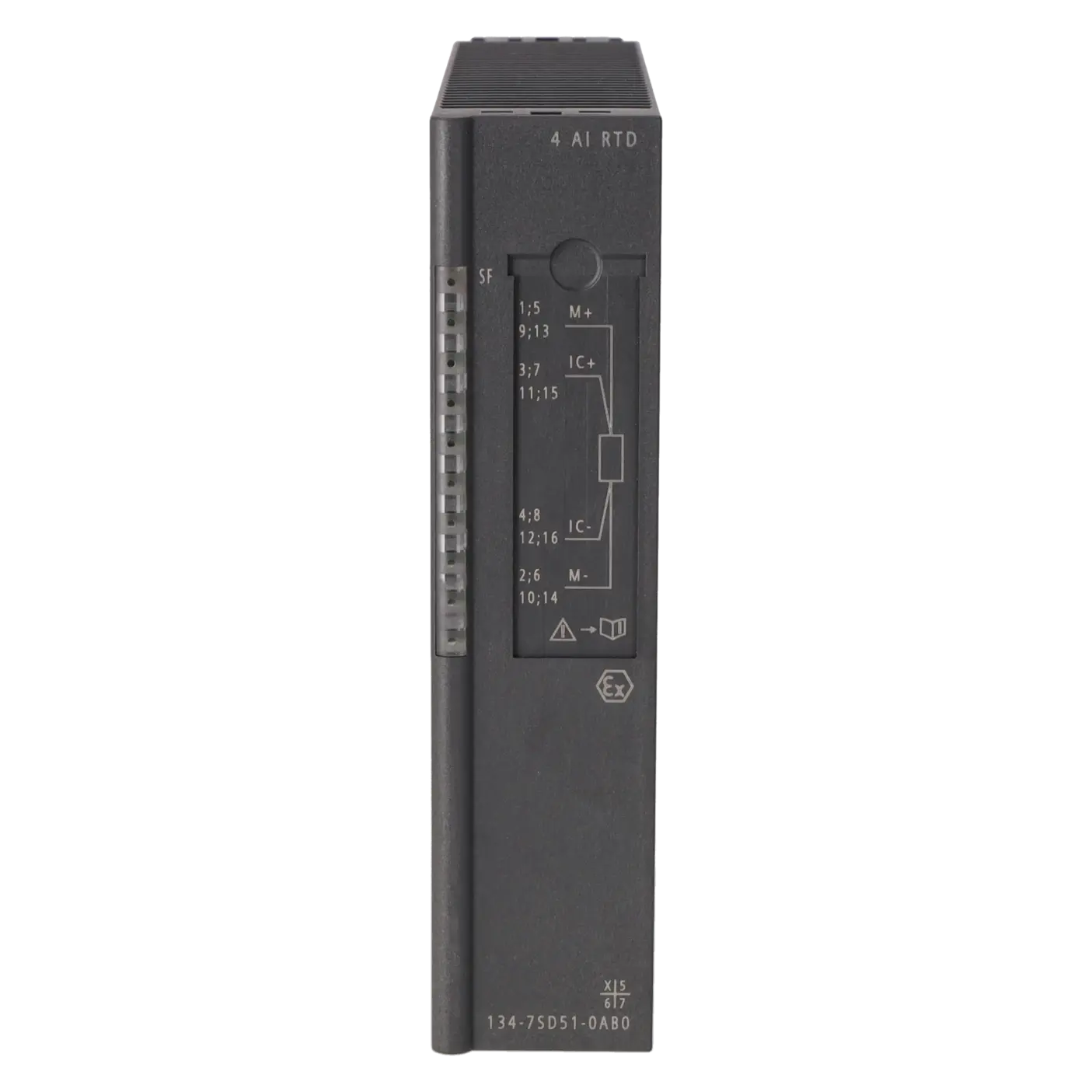
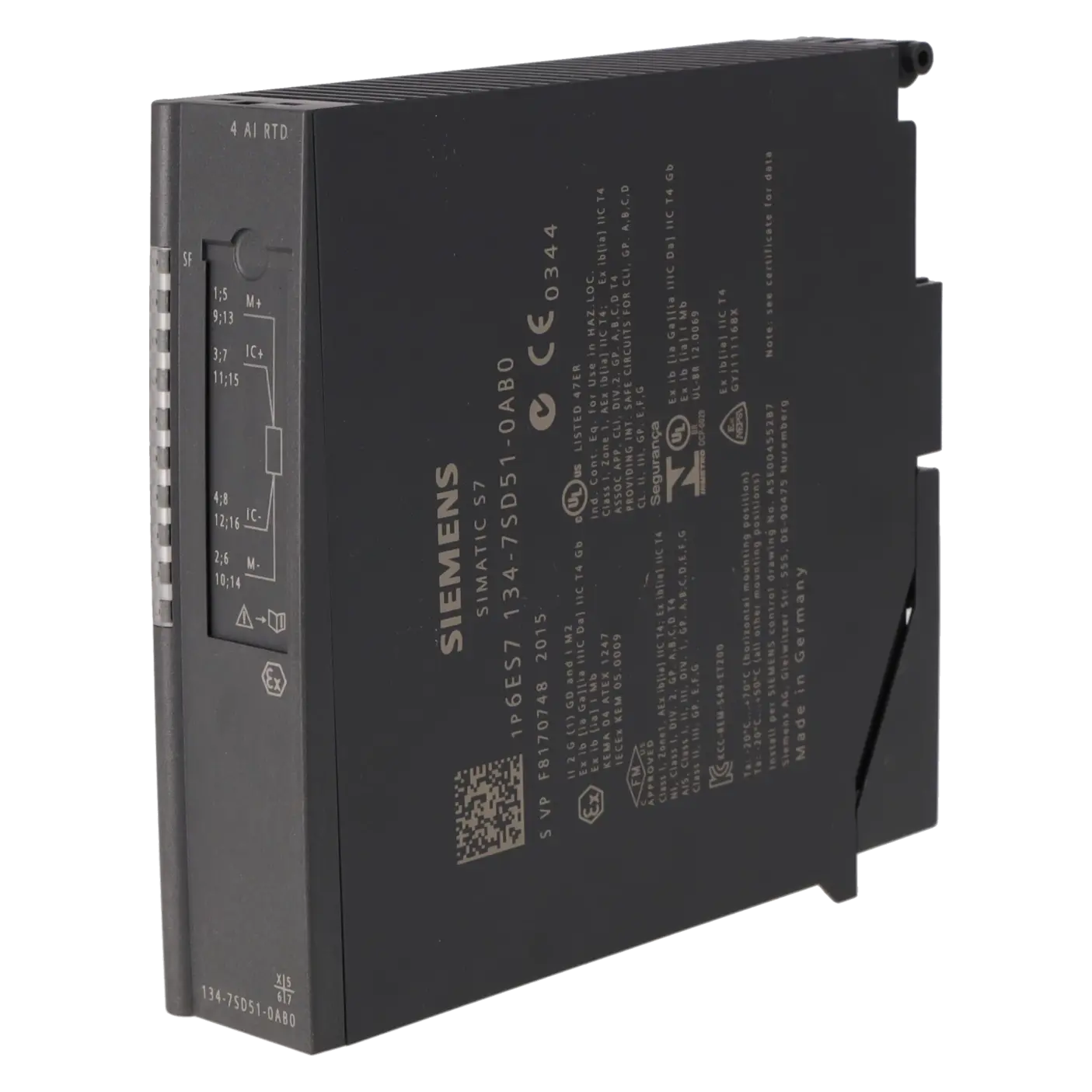
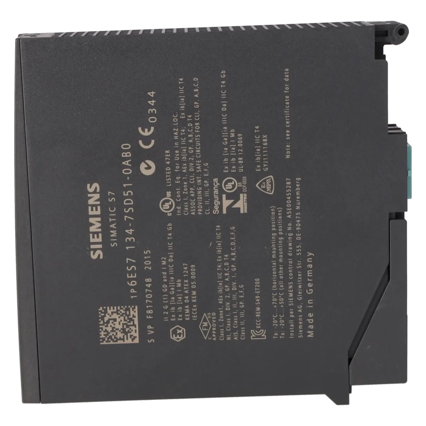
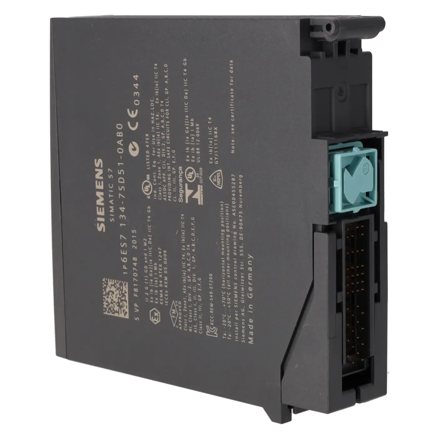
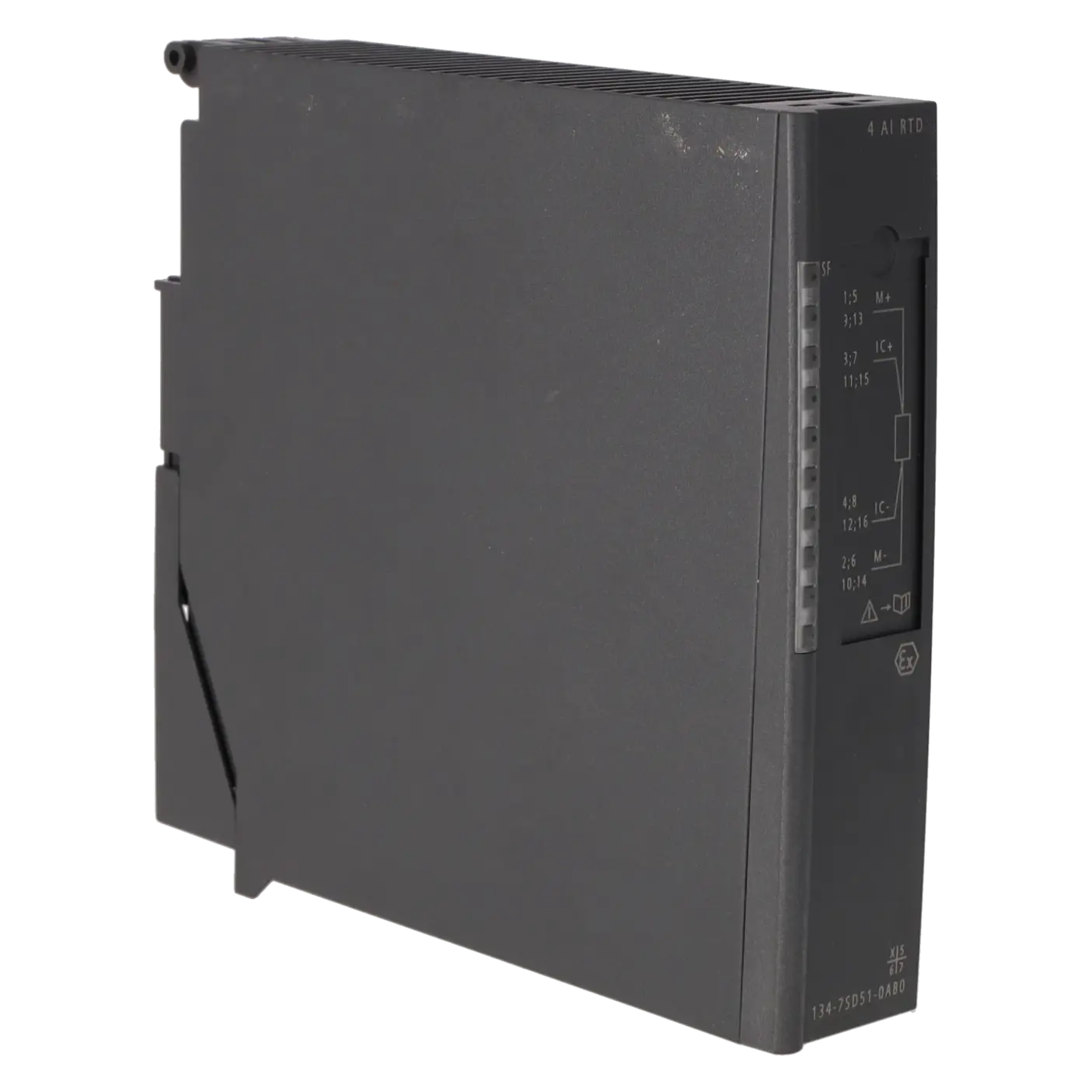
4AI RTD |
| HW functional status |
4 |
| Firmware version |
V1.1.0 |
| Product function |
|
| ● Isochronous mode |
No |
| CiR - Configuration in RUN |
|
| Reparameterization possible in RUN |
Yes |
| Installation type/mounting |
|
| Rack mounting |
No |
| Front mounting |
Yes |
| Rail mounting |
Yes |
| Wall mounting/direct mounting |
No |
| Supply voltage |
|
| Type of supply voltage |
DC |
| permissible range, lower limit (DC) |
20.4 V |
| permissible range, upper limit (DC) |
28.8 V |
| Input current |
|
| Current consumption, typ. |
19 mA |
| from load voltage (power bus), max. |
22 mA |
| Power loss |
|
| Power loss, typ. |
0.4 W |
| Hardware configuration |
|
| Fieldbus connection via separate transceiver |
Yes |
| Analog inputs |
|
| Number of analog inputs |
4 |
| Cycle time (all channels) max. |
320 ms; 66 ms basic conversion time x 4 channels with interference frequency suppression 60 Hz, 80 ms basic conversion time x 4 channels with interference frequency suppression 50 Hz |
| Technical unit for temperature measurement adjustable |
Yes |
| Input ranges |
|
| ● Voltage |
No |
| ● Current |
No |
| ● Thermocouple |
No |
| ● Resistance thermometer |
Yes |
| ● Resistance |
Yes |
| Input ranges (rated values), resistance thermometer |
|
| ● Ni 100 |
Yes |
| — Input resistance (Ni 100) |
2 000 kΩ |
| ● Pt 100 |
Yes |
| — Input resistance (Pt 100) |
2 000 kΩ |
| Input ranges (rated values), resistors |
|
| ● 0 to 600 ohms |
Yes; also 1 000 ohms |
| — Input resistance (0 to 600 ohms) |
1 000 kΩ |
| Characteristic linearization |
|
| ● Parameterizable |
Yes |
| — for resistance thermometer |
Yes |
| Cable length |
|
| ● shielded, max. |
500 m |
| Analog value generation for the inputs |
|
| Measurement principle |
integrating (Sigma-Delta) |
| Integration and conversion time/resolution per channel |
|
| ● Resolution with overrange (bit including sign), max. |
16 bit |
| ● Integration time, parameterizable |
Yes |
| ● Basic conversion time, including integration time (ms) |
80 ms at 50 Hz; 66 ms at 60 Hz |
| — additional conversion time for wire-break monitoring |
5 ms |
| ● Interference voltage suppression for interference frequency f1 in Hz |
50 / 60 Hz |
| Smoothing of measured values |
|
| ● parameterizable |
Yes; in 4 stages |
| ● Step: None |
Yes; 1x cycle time |
| ● Step: low |
Yes; 4x cycle time |
| ● Step: Medium |
Yes; 32x cycle time |
| ● Step: High |
Yes; 64x cycle time |
| Encoder |
|
| Connection of signal encoders |
|
| ● for resistance measurement with two-wire connection |
Yes |
| ● for resistance measurement with three-wire connection |
Yes |
| ● for resistance measurement with four-wire connection |
Yes |
| Errors/accuracies |
|
| Linearity error (relative to input range), (+/-) |
0.015 % |
| Temperature error (relative to input range), (+/-) |
0.02 %/K |
| Crosstalk between the inputs, min. |
-50 dB |
| Repeat accuracy in steady state at 25 °C (relative to input range), (+/-) |
0.01 % |
| Operational error limit in overall temperature range |
|
| ● Resistance thermometer, relative to input range, (+/-) |
0.15 %; Applies to resistances standard ±0.8 K, climatic ±0.3 K |
| Basic error limit (operational limit at 25 °C) |
|
| ● Resistance thermometer, relative to input range, (+/-) |
0.1 %; Applies to resistances standard ±0.5 K, climatic ±0.2 K |
| Interference voltage suppression for f = n x (f1 +/- 1 %), f1 = interference frequency |
|
| ● Series mode interference (peak value of interference < rated value of input range), min. |
70 dB |
| ● Common mode interference, min. |
90 dB |
| Interfaces |
|
| Number of PROFINET interfaces |
0 |
| Protocols |
|
| Supports protocol for PROFINET IO |
No |
| PROFIsafe |
No |
| PROFIBUS |
No |
| Further protocols |
|
| ● other bus systems |
No |
| Interrupts/diagnostics/status information |
|
| Alarms |
|
| ● Diagnostic alarm |
Yes |
| ● Limit value alarm |
Yes |
| Diagnoses |
|
| ● Diagnostic information readable |
Yes |
| ● Wire break |
Yes; R > 2 kOhm |
| ● Short-circuit |
Yes |
| ● Group error |
Yes |
| Diagnostics indication LED |
|
| ● Group error SF (red) |
Yes |
| Ex(i) characteristics |
|
| Module for Ex(i) protection |
Yes; for more Co/Lo combinations, see certificate IECEx KEM 05.0009 |
| maximum values for connecting terminals for gas group IIC |
|
| ● Uo (no-load voltage), max. |
5.9 V |
| ● Io (short-circuit current), max. |
24 mA |
| ● Po (power output), max. |
36 mW |
| ● Co (permissible external capacity), max. |
43 µF |
| ● Lo (permissible external inductivity), max. |
50 mH |
| Potential separation |
|
| Potential separation analog inputs |
|
| ● between the channels |
No |
| ● between the channels and backplane bus |
Yes |
| ● Between the channels and load voltage L+ |
Yes; Channels and power bus |
| Degree and class of protection |
|
| IP degree of protection |
IP30 |
| Standards, approvals, certificates |
|
| CE mark |
CE 0344 |
| UKCA mark |
DEKRA 21UKEX0088 Importer UK: Siemens plc Manchester M20 2UR |
| cULus |
LISTED E334384 |
| FM approval |
CLASSIFIED 3025852 |
| Suitable for safety functions |
No |
| INMETRO certificate |
UL-BR 12.0069 |
| reference designation according to IEC 81346-2 (2009) |
K |
| Highest safety class achievable in safety mode |
|
| ● acc. to EN 954 |
n.a. |
| ● Performance level according to ISO 13849-1 |
none |
| ● SIL acc. to IEC 61508 |
No |
| Use in hazardous areas |
|
| ● ATEX marking |
II 2 G (1) G Ex ib [ia Ga] IIC T4 Gb II 2 G (1) D Ex ib [ia IIIC Da] IIC T4 Gb I M2 Ex ib [ia] I Mb |
| ● ATEX certificate |
KEMA 04 ATEX 1247 |
| ● IECEx |
IECEx KEM 05.0009 |
| ● CCC Ex |
2020322316002940 |
| ● EAC Ex |
PB Ex ib [ia] I Mb 1Ex ib [ia Ga] IIC T4 Gb [Ex ia Da] IIIC |
| ● FM marking |
Class I, Zone 1 AEx ib [ia] IIC T4 Ex ib IIC T4 NI, Class I, DIV.2, GP. A,B,C,D T4 AIS, Class I, DIV.1, GP. A,B,C,D T4 DIP Class II, III, GP. E,F,G |
| ● Explosion protection category for gas |
ATEX gas explosion protection, Zone 1 |
| ● Explosion protection category for dust |
ATEX dust explosion protection, Zone 21 always install in corresponding enclosure |
| ● associated equipment (Ex ia) |
Yes |
| ● associated equipment (Ex ib) |
Yes |
| Marine approval |
|
| ● Germanischer Lloyd (GL) |
Yes |
| ● American Bureau of Shipping (ABS) |
Yes |
| ● Bureau Veritas (BV) |
Yes |
| ● Det Norske Veritas (DNV) |
Yes |
| Connection method |
|
| Design of electrical connection |
Screw/spring-type terminal |
| Dimensions |
|
| Width |
30 mm |
| Height |
129 mm |
| Depth |
136.5 mm |
| Weights |
|
| Weight, approx. |
230 g |