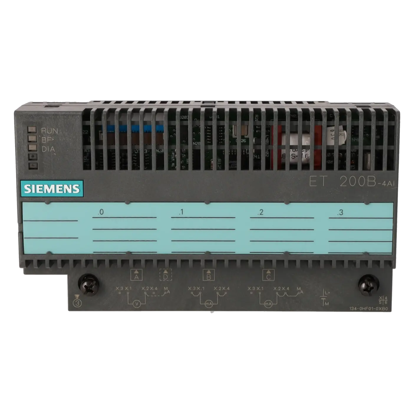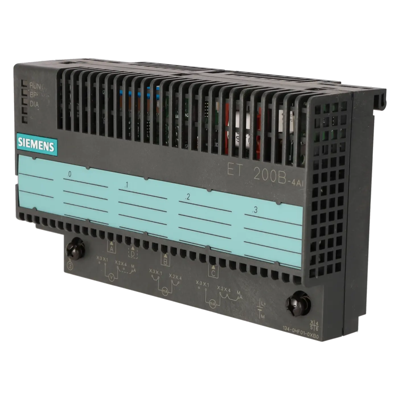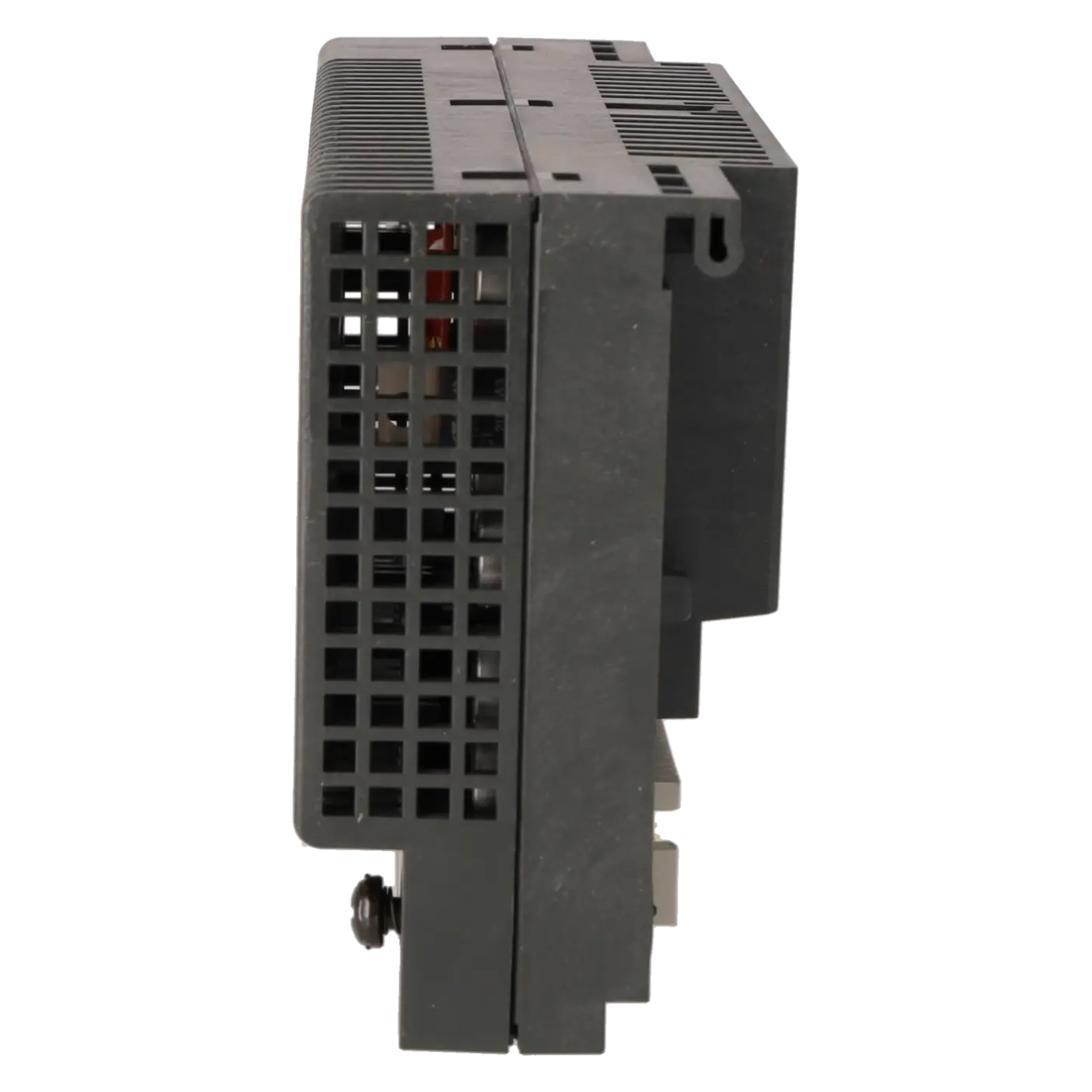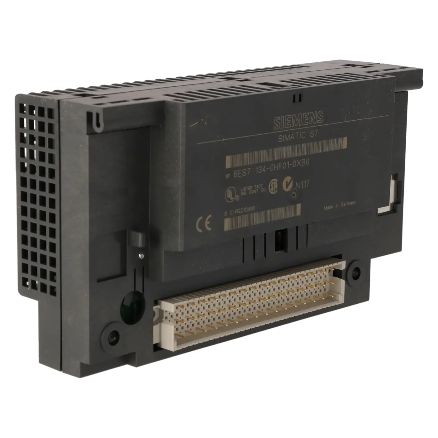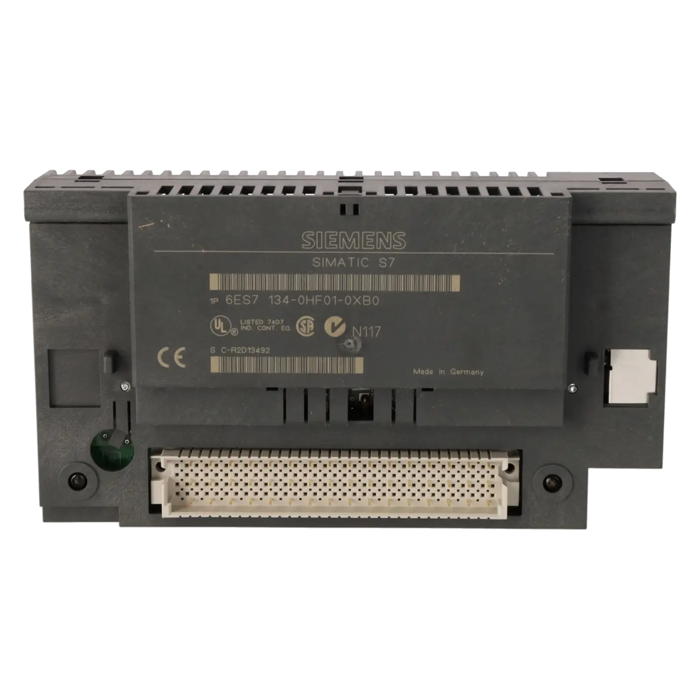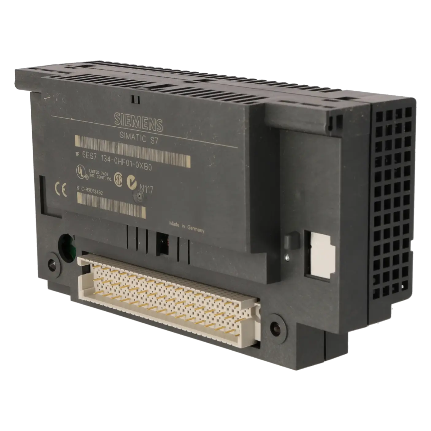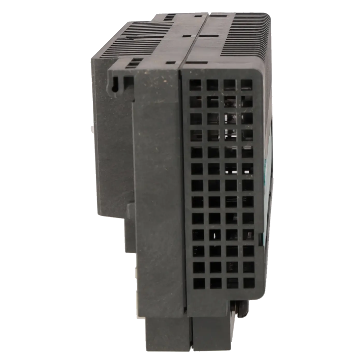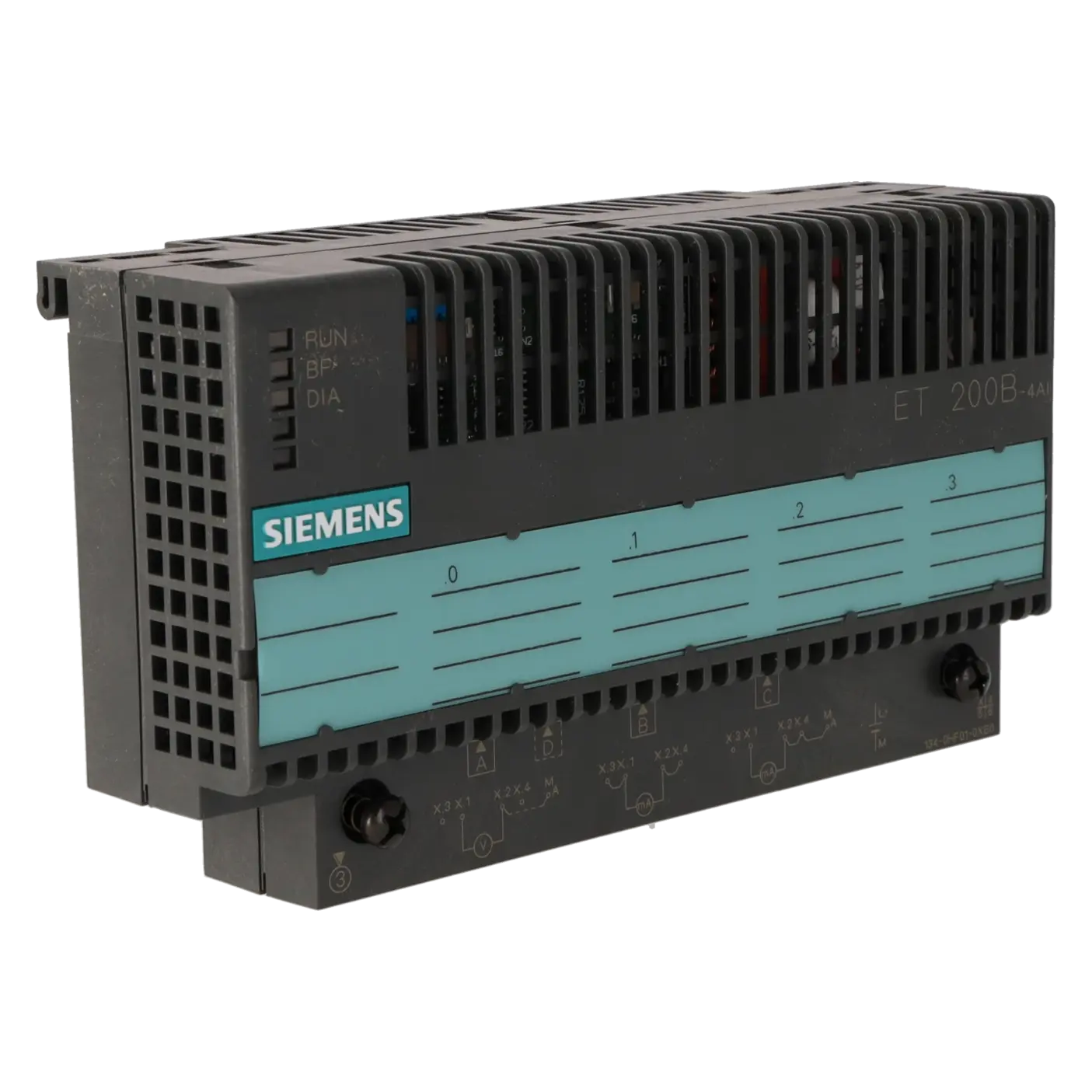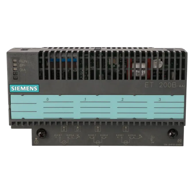
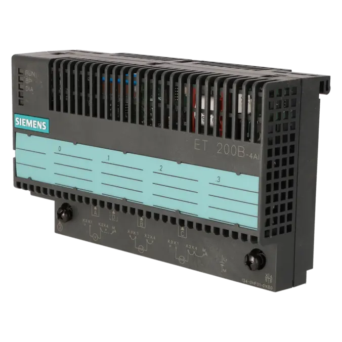
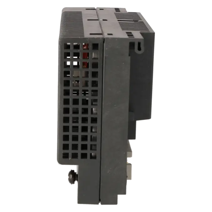
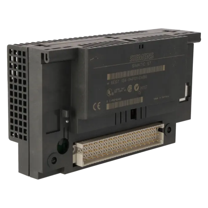
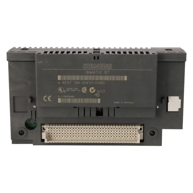
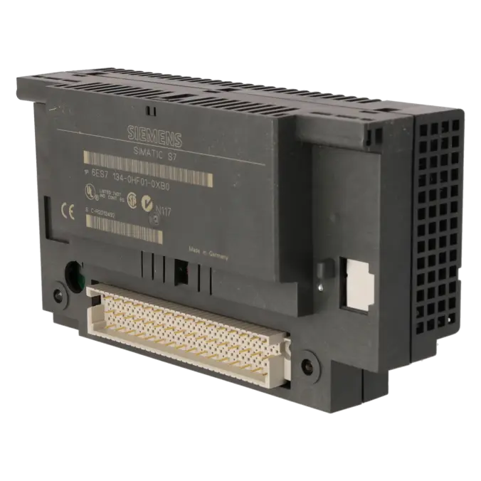
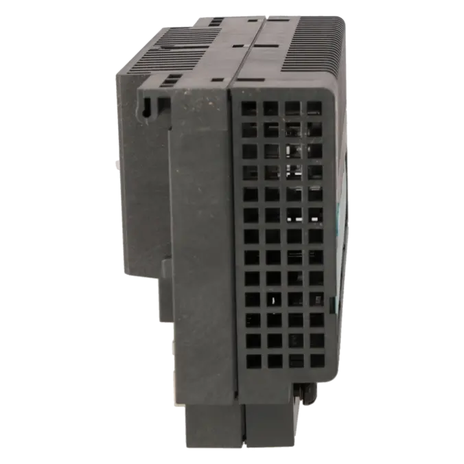
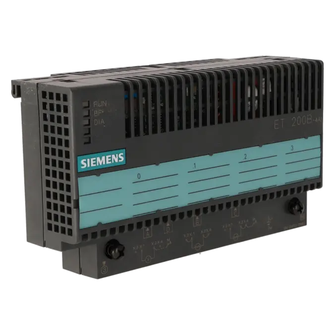
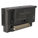
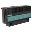
SIEMENS 6ES7134-0HF01-0XB0
- EICHLER-art.no.: K0118103
- EAN: 4025515058403
Product description
SIMATIC DP, ELECTRONIC MODULE ANALOG, FOR ET 200B, W=160MM, 4AI 0(4)...20MA; +/- 10V, FAST CONVERSION, 12 BITS
Services for SIEMENS 6ES7134-0HF01-0XB0
SIEMENS |
6ES7134-0HF01-0XB0 –
additional product information
| Delivery information | |||
|---|---|---|---|
| Export identifier | AL: ECCN: | ||
| Net weight | 0.263 | ||
| Quantity | 1 Stück | ||
| Packaging quantity | 1 | ||
| Additional product information | |||
|---|---|---|---|
| Product status | EOP: 2006-10-01 | ||
| EAN | 4025515058403 | ||
| UPC | / | ||
| Static lot number | 85389091 | ||
| List indicator | / | ||
| Product group | 4467 | ||
| Country of origin | DE | ||
| Compliance with the substance restrictions according to RoHS directive | Since: / | ||
| Product classifications | Version | Classification | |
|---|---|---|---|
| eClass | 4 | / | |
| eClass | 5.1 | / | |
| eClass | 6.0 | / | |
| ETIM | 3 | / | |
| ETIM | 4 | / | |
| ETIM | 5 | / | |
What is 6ES7134-0HF01-0XB0 and where is it used?
The 6ES7134-0HF01-0XB0 is an analogue input module for the decentralised SIMATIC DP / ET 200B peripheral system from Siemens. The module acquires four analogue input signals and is designed for typical industrial signals such as 0/4…20 mA and voltage ranges up to ±10 V. It is primarily used in existing PROFIBUS-DP installations where measured values from pressure, temperature, level or process sensors are collected decentrally and transmitted to a higher-level controller. For maintenance personnel, the module is particularly relevant when existing ET 200B stations must remain in operation, be repaired or be replaced at short notice without fundamentally modifying the existing field wiring or system logic.
Overview of the key technical data and what it means
The module operates with a 24 V DC supply, requires the TB8 terminal block and provides 4 analogue inputs with 12-bit resolution. Supported signal ranges include ±1.25 V, ±2.5 V, ±5 V, ±10 V, 0…20 mA, 4…20 mA and ±20 mA. The integration time of 0.1 ms per channel and a cycle time of up to 5 ms make the module suitable for relatively fast signal changes. Important in practice: wire-break diagnostics are available only in the 4…20 mA range. In addition, the analogue inputs are not electrically isolated, making correct reference potentials and proper wiring particularly important. For longer cable runs, shielded cables up to 100 m are specified.
Product status, life-cycle status and obsolescence
The module belongs to the older ET 200B generation and is therefore clearly a topic for spare parts management, repair strategies and obsolescence planning. The EICHLER data record lists the product status as EOP: 2006-10-01. Siemens most recently classified the MLFB as a spare part; Siemens search results also indicate that no verified successor or replacement product is available. For operators, this means that existing installations can often continue to operate reliably, but the focus shifts towards tested replacement parts, exchange units, strategic stockholding and assessing when repair is more economical than a costly system retrofit.
Available EICHLER services and when they are relevant in practice
For the 6ES7134-0HF01-0XB0, EICHLER offers several options to minimise downtime: repair, exchange, used equipment and new units. Repair is particularly suitable when the existing module must remain compatible with the installed system configuration and a reliable restoration of functionality with a predictable turnaround time is required. EICHLER specifies 2–5 days, including technical cleaning, preventive maintenance, comprehensive functional testing and a minimum 24-month warranty. In cases of urgent production requirements, an exchange unit is often the fastest solution. Used units can be attractive for cost-conscious spare parts strategies, while new units provide maximum reserve where availability permits. This allows system functionality to be maintained even in the face of obsolescence without immediately triggering a retrofit project.
| Attribute | Value |
|---|---|
| Usable terminal block | TB8 |
| Supply voltage | |
| Rated value (DC) | 24 V; Value at t < 0.5 s: 35 V |
| permissible range, lower limit (DC) | 18.5 V |
| permissible range, upper limit (DC) | 30.2 V |
| Input current | |
| Current consumption, typ. | 70 mA; Logic |
| Power loss | |
| Power loss, typ. | 1.8 W |
| Analog inputs | |
| Number of analog inputs | 4 |
| permissible input voltage for voltage input (destruction limit), max. | 30 V; ±30 V (static) or ±75 V (pulse for max. 1 ms and mark to space ratio 1:20) |
| permissible input current for current input (destruction limit), max. | 24 mA |
| Cycle time (all channels) max. | 5 ms |
| Input ranges | |
| ● Voltage | Yes |
| ● Current | Yes |
| Input ranges (rated values), voltages | |
| ● -1.25 V to +1.25 V | Yes |
| — Input resistance (-1.25 V to +1.25 V) | 100 kΩ |
| ● -10 V to +10 V | Yes |
| — Input resistance (-10 V to +10 V) | 100 kΩ |
| ● -2.5 V to +2.5 V | Yes |
| — Input resistance (-2.5 V to +2.5 V) | 100 kΩ |
| ● -5 V to +5 V | Yes |
| — Input resistance (-5 V to +5 V) | 100 kΩ |
| Input ranges (rated values), currents | |
| ● 0 to 20 mA | Yes |
| — Input resistance (0 to 20 mA) | 125 Ω |
| ● -20 mA to +20 mA | Yes |
| — Input resistance (-20 mA to +20 mA) | 125 Ω |
| ● 4 mA to 20 mA | Yes |
| — Input resistance (4 mA to 20 mA) | 125 Ω |
| Cable length | |
| ● shielded, max. | 100 m |
| Analog value generation for the inputs | |
| Measurement principle | successive approximation |
| Integration and conversion time/resolution per channel | |
| ● Resolution with overrange (bit including sign), max. | 12 bit; Two's complement |
| ● Integration time (ms) | 0.1 ms / channel |
| Encoder | |
| Connection of signal encoders | |
| ● for voltage measurement | Yes |
| ● for voltage measurement as 2-wire transducer | Yes |
| ● for current measurement as 2-wire transducer | Yes |
| ● for current measurement as 4-wire transducer | Yes |
| Errors/accuracies | |
| Operational error limit in overall temperature range | |
| ● Voltage, relative to input range, (+/-) | 32 %; 0 to 60°C |
| ● Current, relative to input range, (+/-) | 41 %; 0 to 60°C |
| Basic error limit (operational limit at 25 °C) | |
| ● Voltage, relative to input range, (+/-) | 0.15 % |
| ● Current, relative to input range, (+/-) | 0.2 % |
| Interference voltage suppression for f = n x (f1 +/- 1 %), f1 = interference frequency | |
| ● Common mode interference, min. | 70 dB; Upp < 1 V |
| Interfaces | |
| PROFIBUS DP | |
| ● Transmission rate, max. | 12 Mbit/s |
| Protocols | |
| Bus protocol/transmission protocol | PROFIBUS DP |
| Interrupts/diagnostics/status information | |
| Alarms | |
| ● Diagnostic alarm | Yes; Parameterizable |
| ● Limit value alarm | Yes; Parameterizable, channels 0 and 2 |
| Diagnoses | |
| ● Overrange | Yes; Rated range |
| ● Wire-break in signal transmitter cable | Yes; Measuring range 4 to 20 mA only |
| Diagnostics indication LED | |
| ● RUN LED | Yes |
| ● Bus fault BF (red) | Yes |
| Potential separation | |
| between electronic block and PROFIBUS DP | Yes |
| Potential separation analog inputs | |
| ● Potential separation analog inputs | No |
| Permissible potential difference | |
| between the inputs (UCM) | max. ±10 V |
| Between the inputs and MANA (UCM) | max. ±1 V |
| Ambient conditions | |
| Ambient temperature during operation | |
| ● horizontal installation, min. | 0 °C |
| ● horizontal installation, max. | 60 °C; 41 °C for other mountings |
| Air pressure acc. to IEC 60068-2-13 | |
| ● permissible range, lower limit | 795 hPa |
| ● permissible range, upper limit | 1 080 hPa |
| Relative humidity | |
| ● Operation, min. | 15 % |
| ● Operation, max. | 95 %; RH class 2 in accordance with IEC 1131-2 |
| Vibrations | |
| ● Operation, tested according to IEC 60068-2-6 | Yes; IEC 68, Part 2-6; 10 to 57 Hz; (constant amplitude 0.075 mm); 57 to 150 Hz; (constant acceleration 1 g) |
| Shock testing | |
| ● tested according to IEC 60068-2-27 | Yes; IEC 68, Part 2-27; half-sine, 15 g, 11 ms |
| Connection method | |
| Design of electrical connection for the inputs and outputs | Screw-type and spring-loaded terminals, permanent wiring; 3 and 4-wire connection |
| Dimensions | |
| Width | 160 mm; EB and TB |
| Height | 130 mm; EB and TB |
| Depth | 60 mm; EB and TB |
| Weights | |
| Weight, approx. | 550 g; EB and TB |
| Fault description | Possible solution |
|---|---|
| Why does the 6ES7134-0HF01-0XB0 report a wire break or underrange condition with a 4…20 mA signal? | First check whether the channel is actually parameterised for 4…20 mA operation. The module supports wire-break diagnostics only in this measuring range. Siemens also notes that modules up to and including Release 2 may report an underrange condition instead of a wire-break indication when a wire break occurs. Therefore, check the loop current, sensor supply, TB8 terminal assignment and the actual raw value before classifying the module as defective. |
| Why am I not getting a plausible measured value from the ET 200B 4AI module? | In many cases, the cause is an incorrect measuring-range parameterisation or an unsuitable value format. Several voltage and current ranges as well as different analogue value representations are documented for the ET 200B 4AI. Therefore, check the channel range, scaling, address assignment and whether the transmitter is correctly wired as a 2-wire or 4-wire transmitter. Especially in older installations, swapped signal wires or incorrect TB8 terminal assignments can quickly result in significantly offset or negative values. |
| Why is the BF LED illuminated and the ET 200B station cannot be reached via PROFIBUS? | The module features a red BF LED for bus faults. Check the bus connector, cable, terminating resistors and, above all, the station address. Siemens documents that a modified station address on ET 200B terminal blocks is only adopted after a STOP-RUN transition. If the station remains invisible despite correct wiring, performing this restart is the next logical troubleshooting step. |
| Why does the module not start correctly after reconfiguration or after changing the type file? | For analogue ET 200B modules, a STOP-RUN transition must be performed on the analogue module after reconfiguration using a different type file version, for example when changing between SIxxxAD.200 and SIxxxBD.200. Without this step, parameterisation and communication may remain faulty. It should also be noted that the diagnostic data of ET 200B modules is not updated while the DP master remains in CLEAR mode. |
| Why does the analogue module briefly reset when a diagnostic message occurs? | Siemens describes that ET 200B analogue modules with Revision 02 may reset when a diagnostic signal is triggered, causing the defined data transmission to stop temporarily. If this behaviour occurs, check the revision level, the diagnostic cause and the trigger condition of the affected channel. In critical applications, it should then be assessed whether repair, replacement or spare-part stockholding represents the safer long-term solution. |
Is 6ES7134-0HF01-0XB0 an analogue input module or an analogue output module?
The 6ES7134-0HF01-0XB0 is an analogue input module with 4 inputs. The Siemens designation is 4AI 0(4)…20 mA; ±10 V. The module is therefore intended for acquiring analogue sensor signals and not for outputting analogue control values. This distinction is important for correct spare-part ordering, as ET 200B input and output modules may appear similar externally but are not functionally interchangeable.
Which terminal block is suitable for 6ES7134-0HF01-0XB0?
The appropriate terminal block is the TB8. This information is important for purchasing and maintenance because, in older ET 200B stations, not only the electronics module but also the corresponding terminal block must match the existing configuration. When sourcing a replacement part, it should therefore always be verified whether only the electronics module is defective or whether the complete combination of module and TB8 needs to be considered.
Which measuring ranges are supported by the module?
The module supports voltage measuring ranges of ±1.25 V, ±2.5 V, ±5 V and ±10 V, as well as current measuring ranges of 0…20 mA, 4…20 mA and ±20 mA. This allows the module to be used in many existing installations for both classic process signals and a wide variety of transmitter types. For reliable commissioning, however, the measuring range and wiring must exactly match the connected sensor, otherwise seemingly incorrect raw values or diagnostic messages may occur.
Is there an official successor for 6ES7134-0HF01-0XB0?
No verified official successor is identified in the available Siemens product sources. Siemens lists the MLFB as an older spare-part item, while a SiePortal search result indicates that the product has been discontinued without a replacement product. For operators, this means that supply is typically secured through repair services, exchange units, tested used equipment or existing spare-part inventories.
Can the module detect a wire break in a 4…20 mA circuit?
Yes, the module supports wire-break diagnostics, but only in the 4…20 mA measuring range. This diagnostic function is not available in the same form for the 0…20 mA range. This is important during troubleshooting because incorrect channel parameterisation can result in an implausible measured value or an underrange indication instead of a clear wire-break message. For this reason, 4…20 mA remains the preferred choice in many existing installations where diagnostic capability is required.
When is repair more appropriate than replacement or purchasing a new unit?
Repair is generally the better option when the existing module remains part of an installed system, the plant configuration should remain unchanged and a technically verified return to service is more economical than a modification project. An exchange unit is the stronger option when production downtime must be minimised immediately. According to the EICHLER product page, repair is available with a turnaround time of 2–5 days, while exchange, used and new units are available within 1–3 days. For decision-makers, the choice is primarily a balance between downtime costs, supply security and investment level.
Can 6ES7134-0HF01-0XB0 also be operated with a non-Siemens DP master?
In principle, yes, but only under certain conditions. Siemens states that ET 200B analogue modules from Release 3 onwards also support the standard identifier format. One requirement is that the third-party master cyclically sends the UNCLEAR control command and is capable of processing diagnostic frames of up to 29 bytes. If these requirements are not fulfilled, the configuration must be matched very carefully to the master environment.