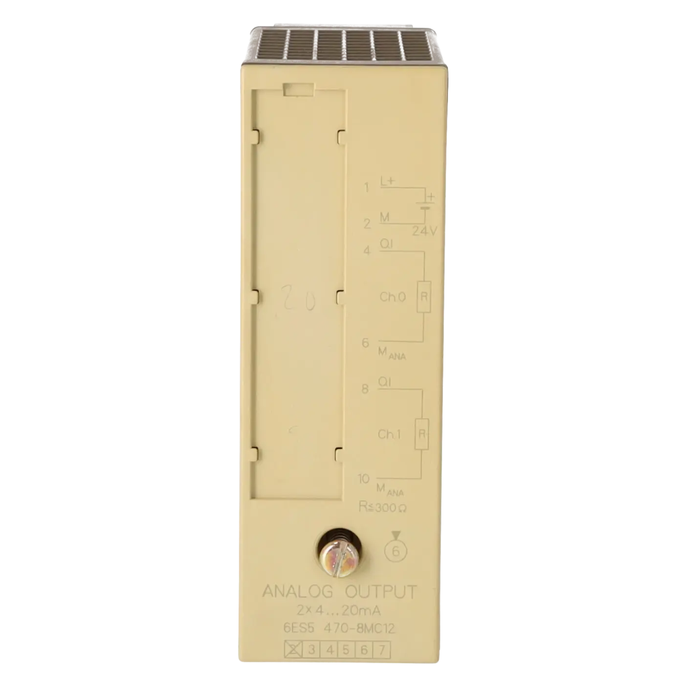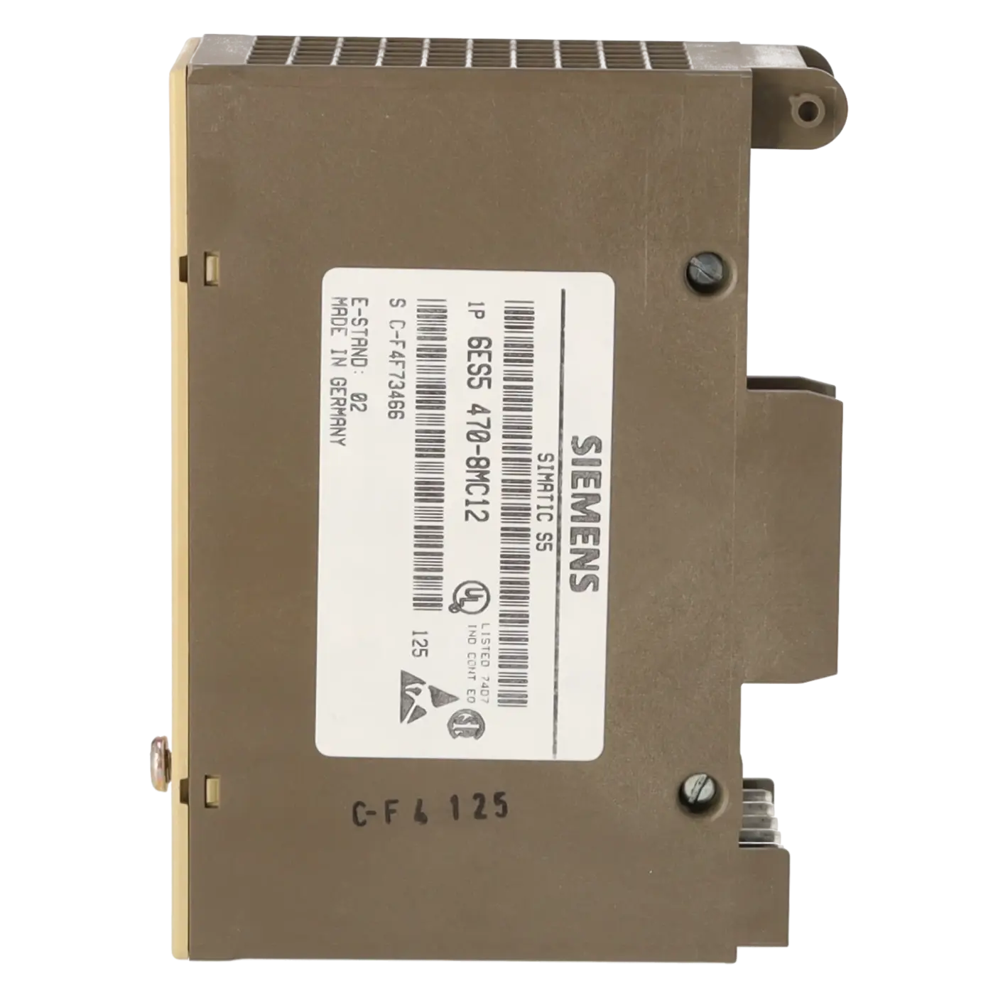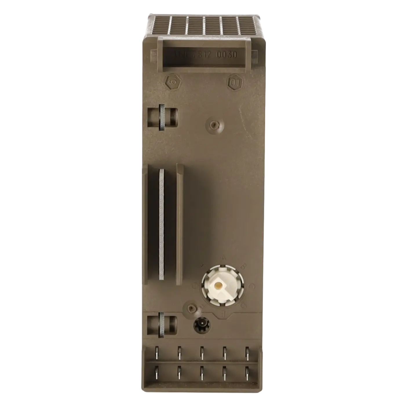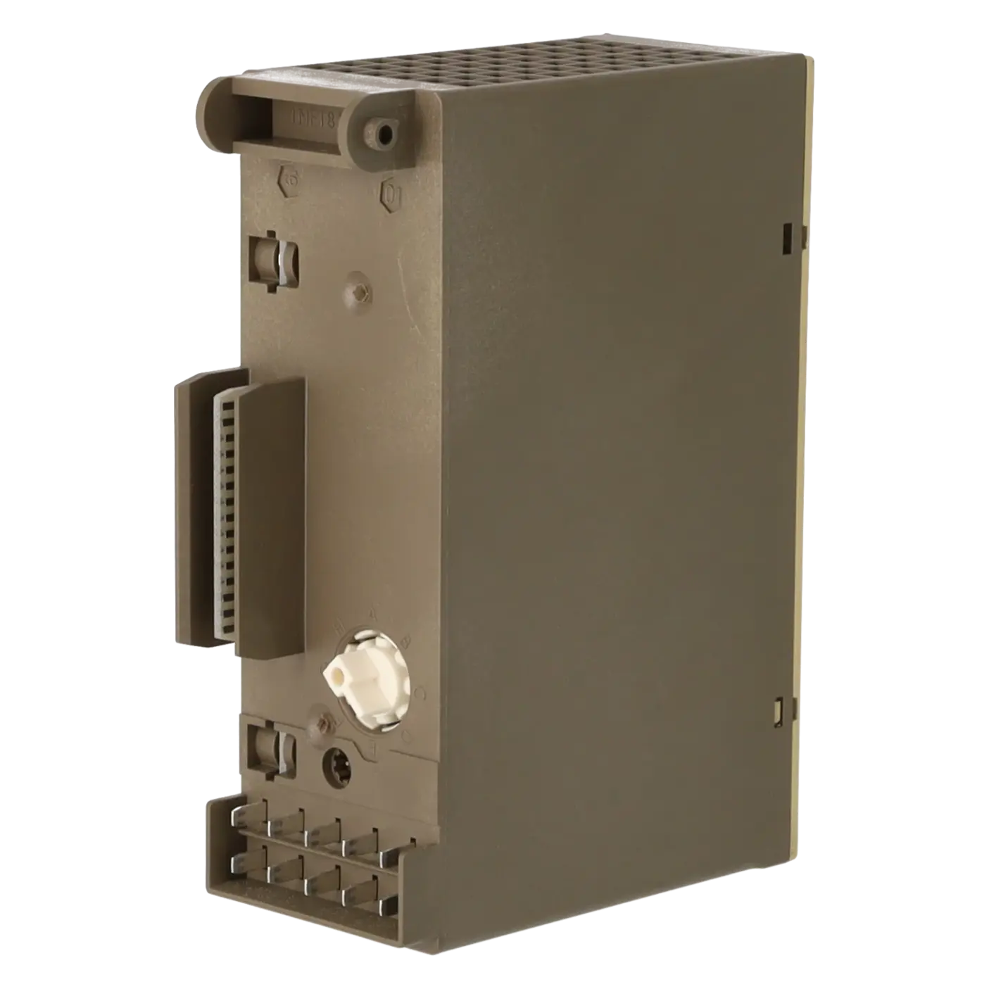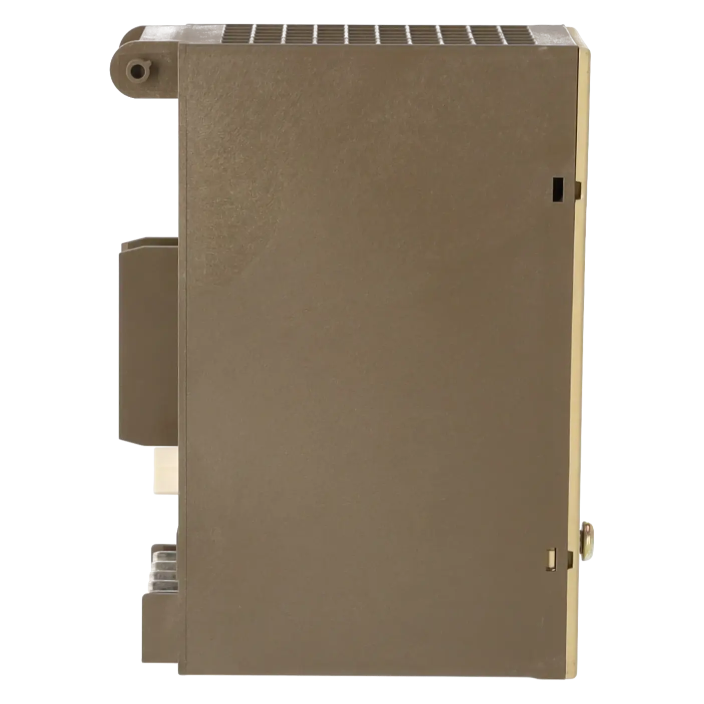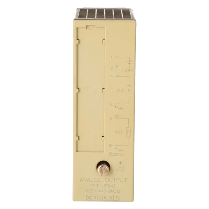
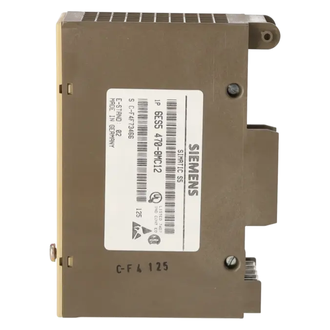
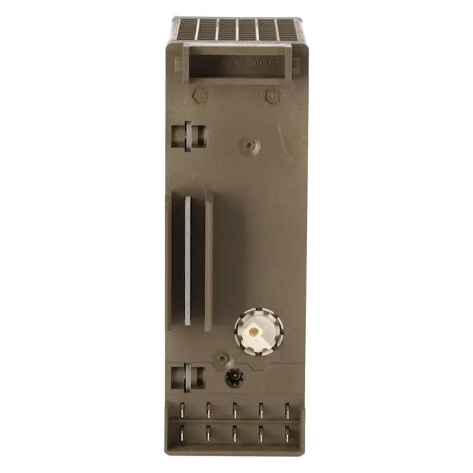
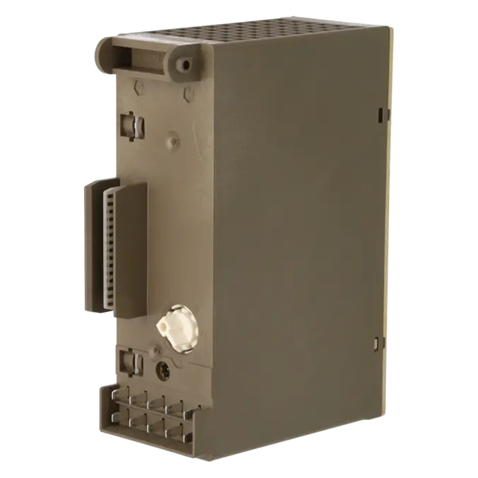
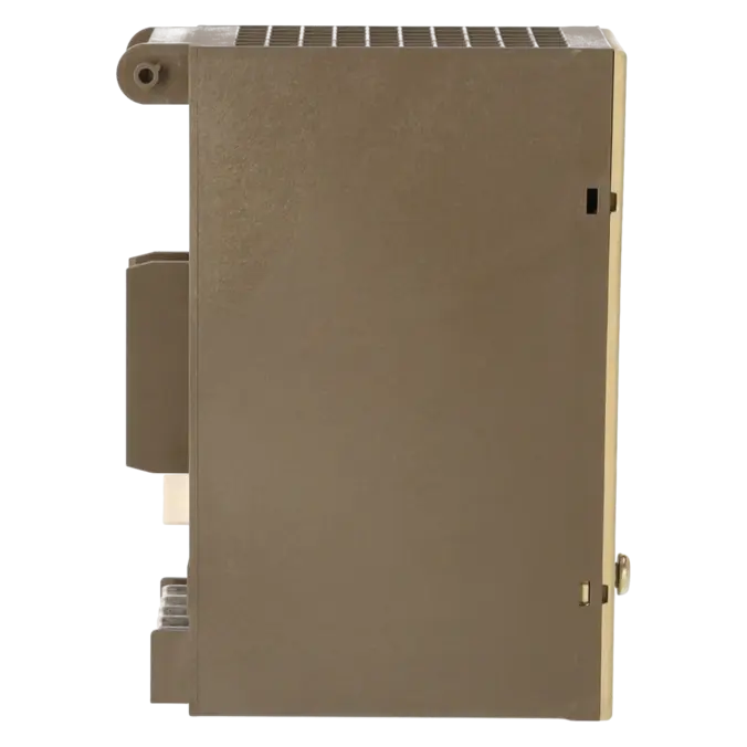
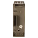
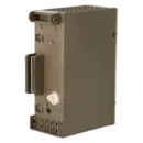

SIEMENS 6ES5470-8MC12
- EICHLER-art.no.: K0117589
- EAN: 4025515054283
Product description
SIMATIC S5, Analog output 470 Isolated for S5-90U/-95U/-100U, ET 100U, ET 200U 2 outputs +4 to 20 mA
Services for SIEMENS 6ES5470-8MC12
SIEMENS |
6ES5470-8MC12 –
additional product information
| Delivery information | |||
|---|---|---|---|
| Export identifier | AL: ECCN: | ||
| Net weight | 0.326 | ||
| Quantity | 1 Stück | ||
| Packaging quantity | 1 | ||
| Additional product information | |||
|---|---|---|---|
| Product status | EOP: 2004-10-01 | ||
| EAN | 4025515054283 | ||
| UPC | / | ||
| Static lot number | 85389091 | ||
| List indicator | / | ||
| Product group | 4234 | ||
| Country of origin | DE | ||
| Compliance with the substance restrictions according to RoHS directive | Since: / | ||
| Product classifications | Version | Classification | |
|---|---|---|---|
| eClass | 4 | / | |
| eClass | 5.1 | / | |
| eClass | 6.0 | / | |
| ETIM | 3 | / | |
| ETIM | 4 | / | |
| ETIM | 5 | / | |
What is 6ES5470-8MC12 and where is it used?
The SIEMENS 6ES5470-8MC12 is a SIMATIC S5 Analogue Output 470 assembly with 2 electrically isolated current outputs in the range of 4 to 20 mA. The assembly is designed for use with S5-90U, S5-95U, S5-100U, ET 100U and ET 200U systems. It is used wherever a standardised current signal must be transmitted from an S5 controller to field devices, such as actuators, drives, controllers, displays or other 4–20 mA inputs. For maintenance personnel, the assembly is particularly relevant when an existing S5 system is to remain in operation and an exactly matching replacement assembly is required. The content is structured for the EICHLER product detail page.
Overview of the most important technical data and what it means
From a technical perspective, the 6ES5470-8MC12 provides 2 outputs in the range of 4 to 20 mA, with galvanic isolation from the grounding point and between the outputs. It supports a maximum load resistance of 300 Ω, a capacitive load of less than 100 nF including cabling, a maximum conversion time of 0.15 ms, and digital representation with 11 bits plus sign. In practice, this means that the assembly is designed for traditional current-loop interfaces in automation systems, responds quickly to setpoint changes and requires correct matching of load characteristics and wiring. The assembly is powered by 24 V DC, with a permissible voltage range of 20 to 30 V. When shielded wiring is used, cable lengths of up to 200 m are specified.
Product status, life cycle status and obsolescence status
For procurement purposes, the product life cycle is particularly important. The EICHLER product page lists the assembly with a product status of EOP dated 2004-10-01. In addition, Siemens-related data sheets classify the 6ES5470-8MC12 as a spare part. This clearly indicates an advanced obsolescence status within the SIMATIC S5 product family. For operators of older systems, this means that supply is generally no longer ensured through standard series production, but rather through repair, tested inventory stock, used equipment, exchange solutions and strategic spare parts management. Based on the official product sources reviewed, a reliably verified direct Siemens successor could not be confirmed.
Available EICHLER services and when they are relevant
For this assembly, EICHLER offers repair, exchange, as well as procurement as used equipment or new equipment. These services are particularly relevant for maintenance personnel when a system breakdown must be resolved quickly, for purchasing departments when market availability is limited, and for decision-makers evaluating repair versus replacement. According to the product detail page, the repair service includes technical cleaning, preventive maintenance, comprehensive functional testing and a minimum 24-month warranty. In addition, an optional test report for analogue inputs and analogue outputs is available. This is especially important for obsolete S5 assemblies because it improves the reliability, traceability and long-term availability of existing systems.
| Fault description | Possible solution |
|---|---|
| Why does the 6ES5470-8MC12 not provide a 4–20 mA signal? | First, check the wiring of the two-wire circuit. For correct operation, the load supply must provide 24 V DC at the designated terminals, and the connected device must be present as an actual load within the current loop. Siemens documentation explicitly specifies the two-wire wiring arrangement and the 24 V supply requirement for this assembly. If the loop is open or the supply voltage is missing, no valid output signal can be generated. |
| Why does my S5 switch to STOP when controlling the analogue output? | The most common causes are addressing or programming errors during analogue value output. For S5 systems, Siemens describes the use of FB251 for standardised output to analogue output assemblies. In one technical discussion relating to S5, a STOP condition was traced to the method used for writing to the output words; after correcting the addressing and using FB251, the output functioned correctly. Therefore, systematically check the slot, channel, data format and the transfer of the setpoint value. |
| Why do incorrect values such as 3.984 mA or 20.016 mA appear at the 6ES5470-8MC12 outputs? | The assembly uses a digital representation consisting of 11 bits plus sign and processes left-aligned two's complement values. According to Siemens documentation, the nominal range for 4 to 20 mA corresponds to values between 0 and 1024 units; above and below this range, overrange conditions begin. If raw values are incorrectly scaled or interpreted, apparently implausible current values can result. The solution is to apply correct scaling or to use FB251 with properly configured UGR and OGR limits. |
| Why does the output fail to reach 20 mA or behave unstably? | In this case, the load and cable characteristics should be checked. For the 6ES5470-8MC12, Siemens specifies a maximum load resistance of 300 Ω, a maximum capacitive load of less than 100 nF including cabling, and cable lengths of up to 200 m when shielded wiring is used. The supply voltage must also remain within the permissible range. If any of these limits are exceeded, the output may be unable to maintain the required current value correctly or may behave unstably. |
| Why do I measure no plausible current when the output is unloaded or when measuring at the wrong terminals? | This assembly requires a correctly connected load within the current loop. In an S5 technical discussion, it was explicitly pointed out that measurements taken without a load are of limited value and that selecting the correct measurement points is essential. Therefore, always measure the current within a closed current loop and in accordance with the specified two-wire wiring configuration, rather than measuring across arbitrary terminals to ground. |
Which control systems and peripheral systems are compatible with the 6ES5470-8MC12?
The 6ES5470-8MC12 is designed for SIMATIC S5-90U, S5-95U, S5-100U, as well as ET 100U and ET 200U systems. This compatibility assignment is specified both on the EICHLER product detail page and in Siemens-related data sheets and manuals. For spare parts procurement, this compatibility information is critical because, with S5 assemblies, the exact order number and the correct 4–20 mA signal type are more important than a module designation that only appears superficially similar.
Is the 6ES5470-8MC12 still within an active product life cycle?
No. The assembly is no longer part of an active standard product life cycle. The EICHLER website lists an EOP date of 2004-10-01, and Siemens-related data sheets classify it as a spare part. For operators, this means that availability is now typically maintained through repair, exchange, used inventory stock or selectively available new units rather than through ongoing series production. As a result, obsolescence management and strategic spare parts planning have become significantly more important.
Is there a direct successor to the 6ES5470-8MC12?
A directly verified 1:1 successor could not be reliably confirmed from the official product sources reviewed. Procurement decisions should therefore not be based on an assumed successor but rather on the exact article number, the 4–20 mA signal type, compatibility with the existing rack or peripheral system and documented proof of functionality. This is particularly important in S5 environments to prevent issues such as incorrect wiring, improper scaling or unsuitable channel characteristics following replacement.
How can the 6ES5470-8MC12 be controlled effectively in STEP 5?
Siemens recommends the use of FB251 for analogue output applications. This function block converts values between UGR and OGR into the nominal operating range of the analogue output and simultaneously reports errors resulting from incorrect limit values or range violations. In practice, this is usually the most reliable approach because setpoint values are not simply output as raw data but are properly normalised and scaled in a transparent manner. For maintenance personnel, this simplifies diagnostics and commissioning, particularly when rapid recommissioning is required after a repair or replacement.
When is repair a better option than direct replacement for this assembly?
Repair is particularly advantageous when the existing assembly matches the installed system, the original configuration should be retained and procurement risks associated with S5 spare parts need to be minimised. EICHLER specifically offers repair, exchange, used equipment and new equipment options for this order number. Because the EICHLER repair service includes technical cleaning, preventive maintenance, functional testing and a minimum 24-month warranty, it is often a cost-effective solution that balances rapid availability with long-term supply security.
What should be considered when purchasing a replacement 6ES5470-8MC12 assembly?
The most important factors are the exact order number 6ES5470-8MC12, the output configuration of 2 × 4–20 mA, the galvanic isolation, compatibility with S5-90U, S5-95U, S5-100U, ET 100U or ET 200U, and documented proof that the assembly has been functionally tested. Equally important are the electrical operating conditions, including the 24 V supply voltage, a maximum load resistance of 300 Ω, and the correct two-wire wiring configuration. Selecting a replacement solely because it resembles another AO 470 module can lead to malfunctions despite belonging to the same assembly family.