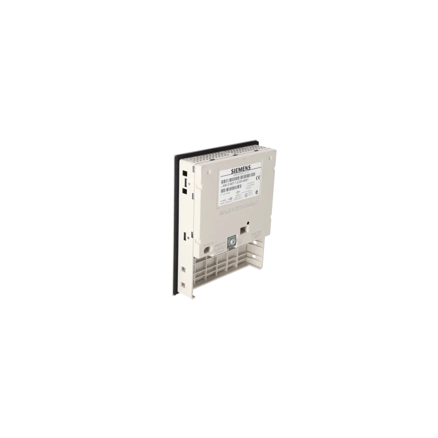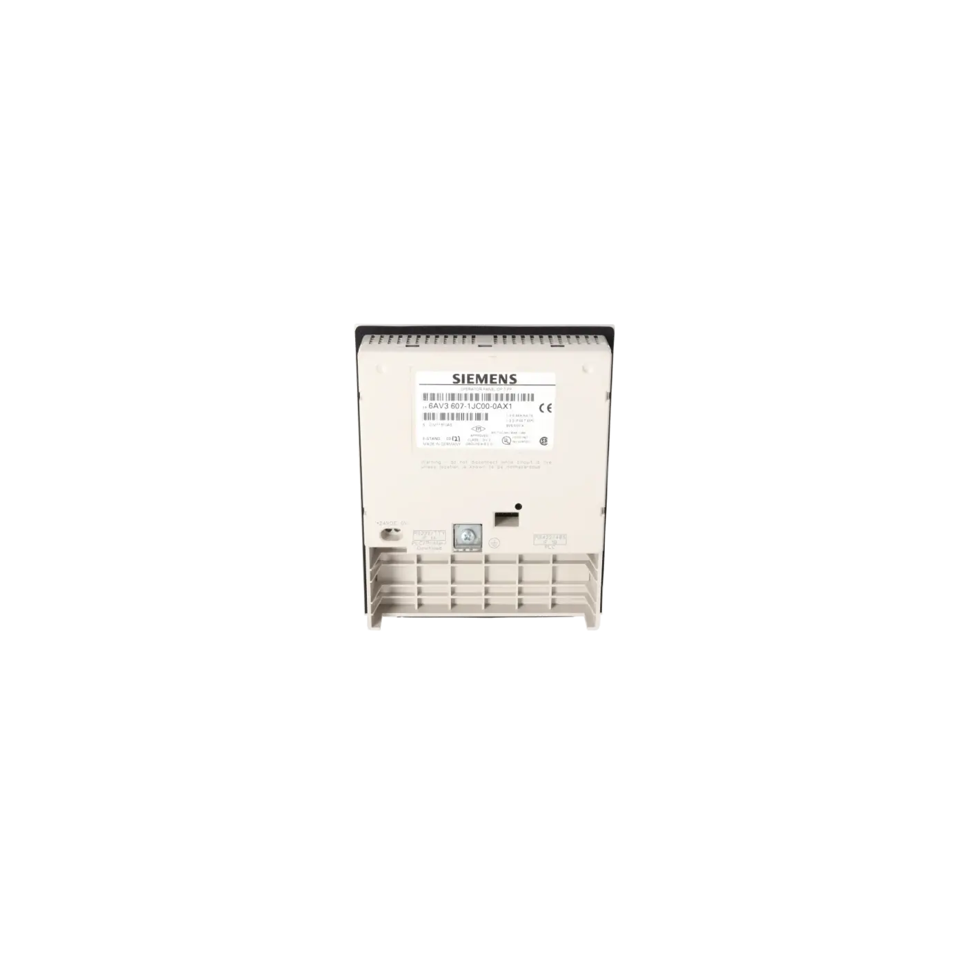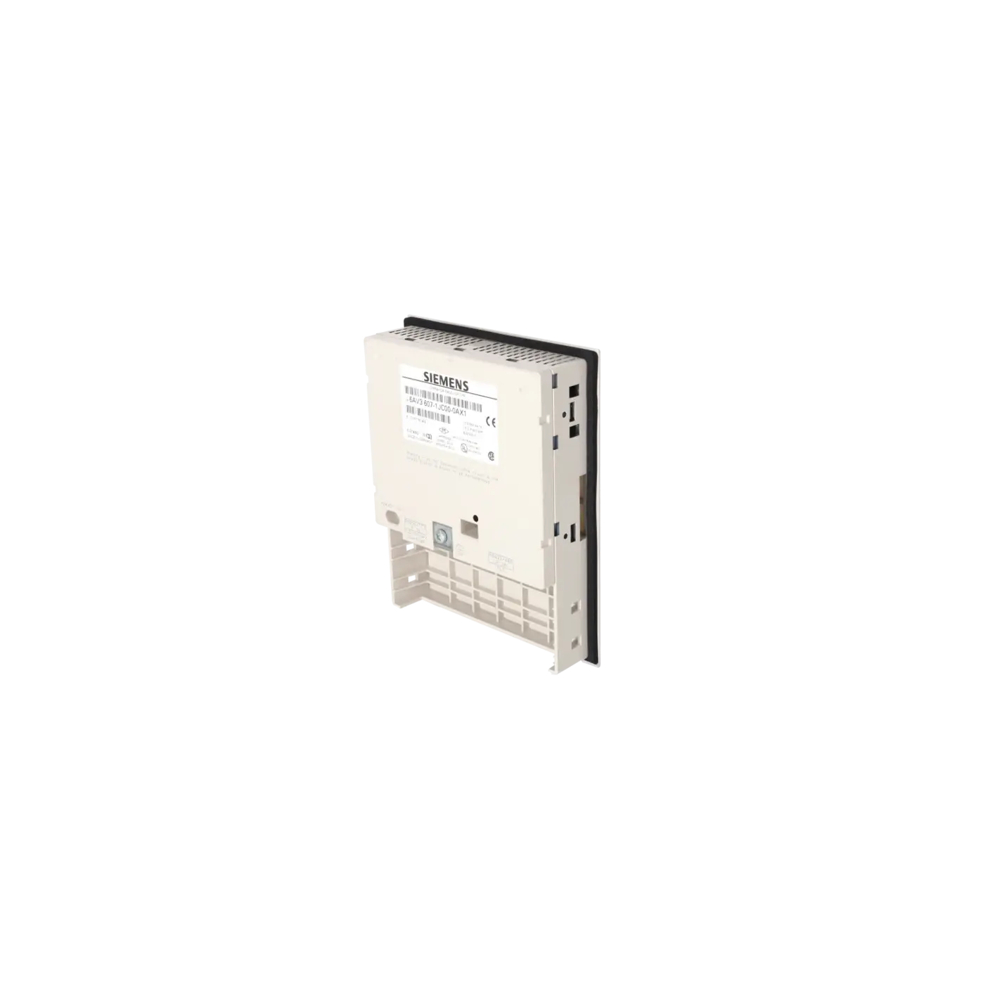
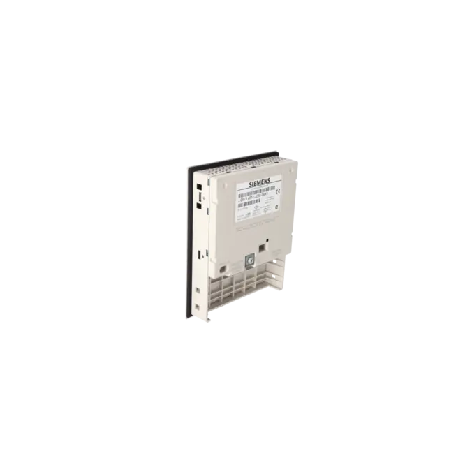


SIEMENS 6AV3607-1JC00-0AX1
-
SIEMENS | HMI | Operator Panels
- EICHLER-art.no.: K0116657
- EAN: 4025515051985
Product description
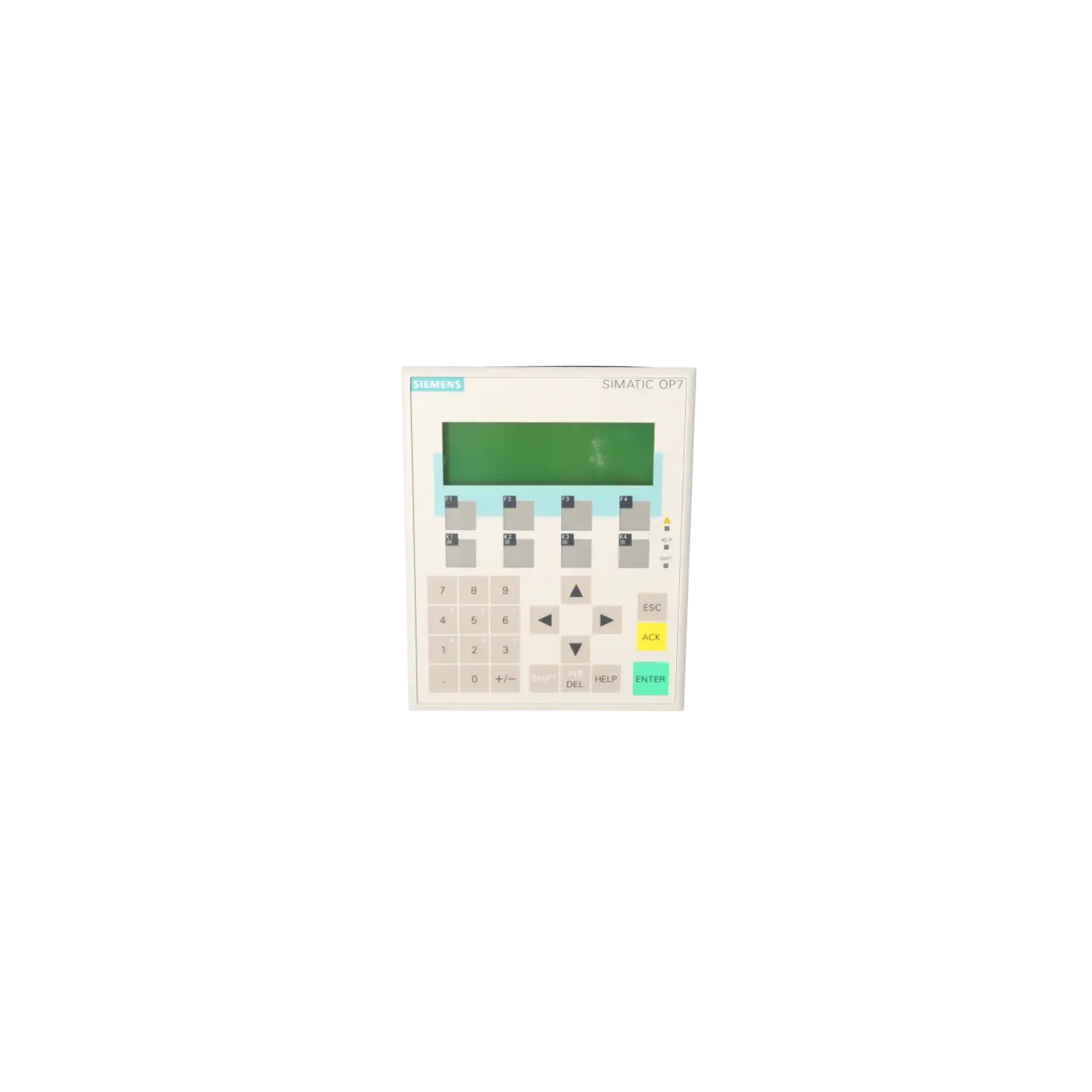
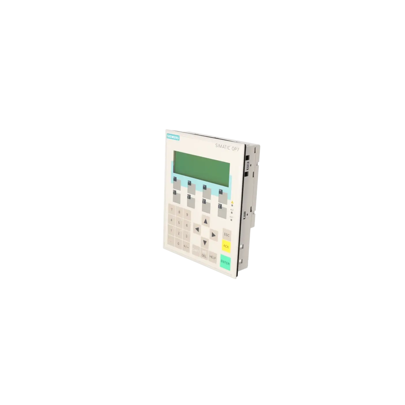
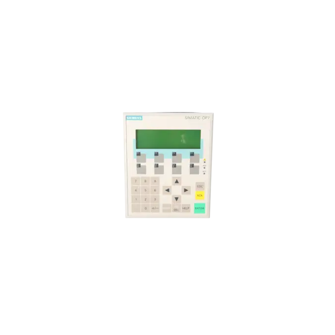
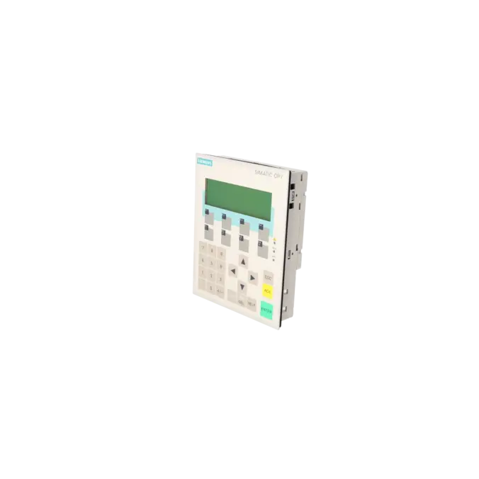
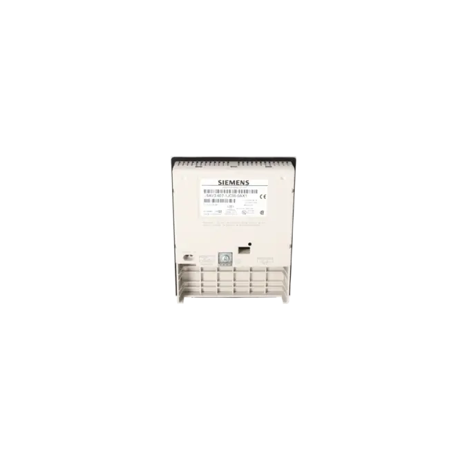
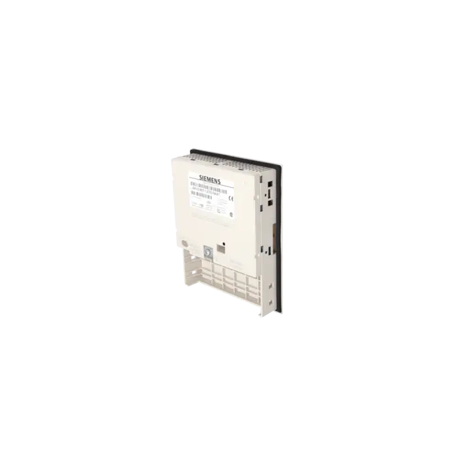
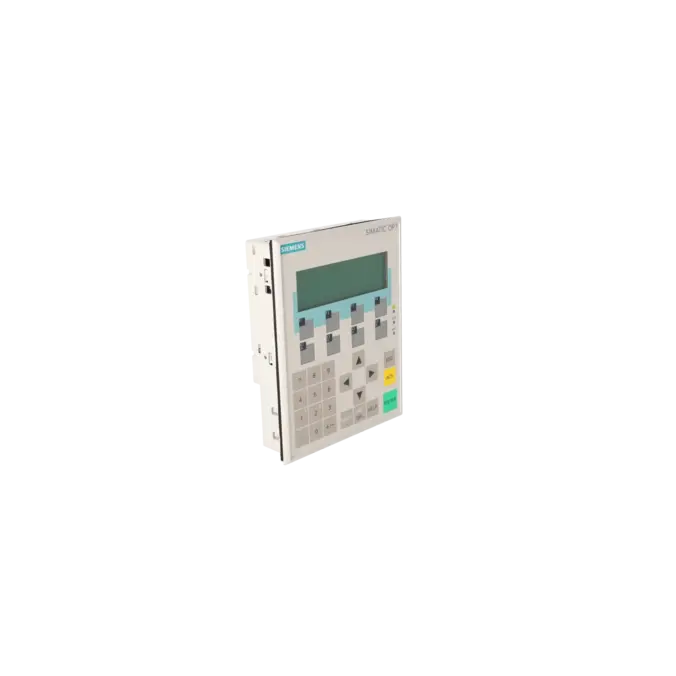
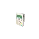
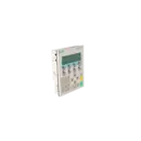
OPERATOR PANEL OP7/PP LC DISPLAY, LED BACKLIT 4-TIER, 20 CHARACTERS/LINE, SIMATIC S5, 505, NATIVE DRIVERS WITH UL/CSA APPROVAL
Services for SIEMENS 6AV3607-1JC00-0AX1
SIEMENS |
6AV3607-1JC00-0AX1 –
additional product information
| Delivery information | |||
|---|---|---|---|
| Export identifier | AL: ECCN: | ||
| Net weight | 0.496 | ||
| Quantity | 1 Stück | ||
| Packaging quantity | 1 | ||
| Additional product information | |||
|---|---|---|---|
| Product status | EOP: 2007-10-01 | ||
| EAN | 4025515051985 | ||
| UPC | / | ||
| Static lot number | 85371098 | ||
| List indicator | / | ||
| Product group | 4368 | ||
| Country of origin | DE | ||
| Compliance with the substance restrictions according to RoHS directive | Since: / | ||
| Product classifications | Version | Classification | |
|---|---|---|---|
| eClass | 4 | / | |
| eClass | 5.1 | / | |
| eClass | 6.0 | / | |
| ETIM | 3 | / | |
| ETIM | 4 | / | |
| ETIM | 5 | / | |
What is the 6AV3607-1JC00-0AX1 and where is it used?
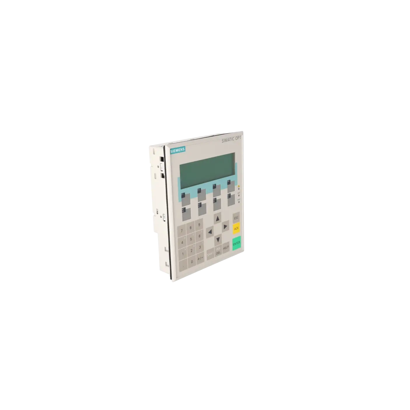
The 6AV3607-1JC00-0AX1 is a SIEMENS SIMATIC HMI OP7/PP operator panel featuring a text-based LC display with LED backlighting and 4 lines of 20 characters. It belongs to the class of key-operated operator devices and is designed for machines and systems where process values, alarms, acknowledgements and basic operating functions are handled via dedicated keys. The OP7/PP variant is intended for SIMATIC S5 and SIMATIC 505 systems using native drivers. For this reason, the panel remains highly relevant in legacy installations, retrofit projects and spare parts strategies for older automation systems. For maintenance and purchasing departments, the exact part number is critical because it defines the communication variant and therefore the technical compatibility of the replacement device.
Overview of the key technical specifications and what they mean
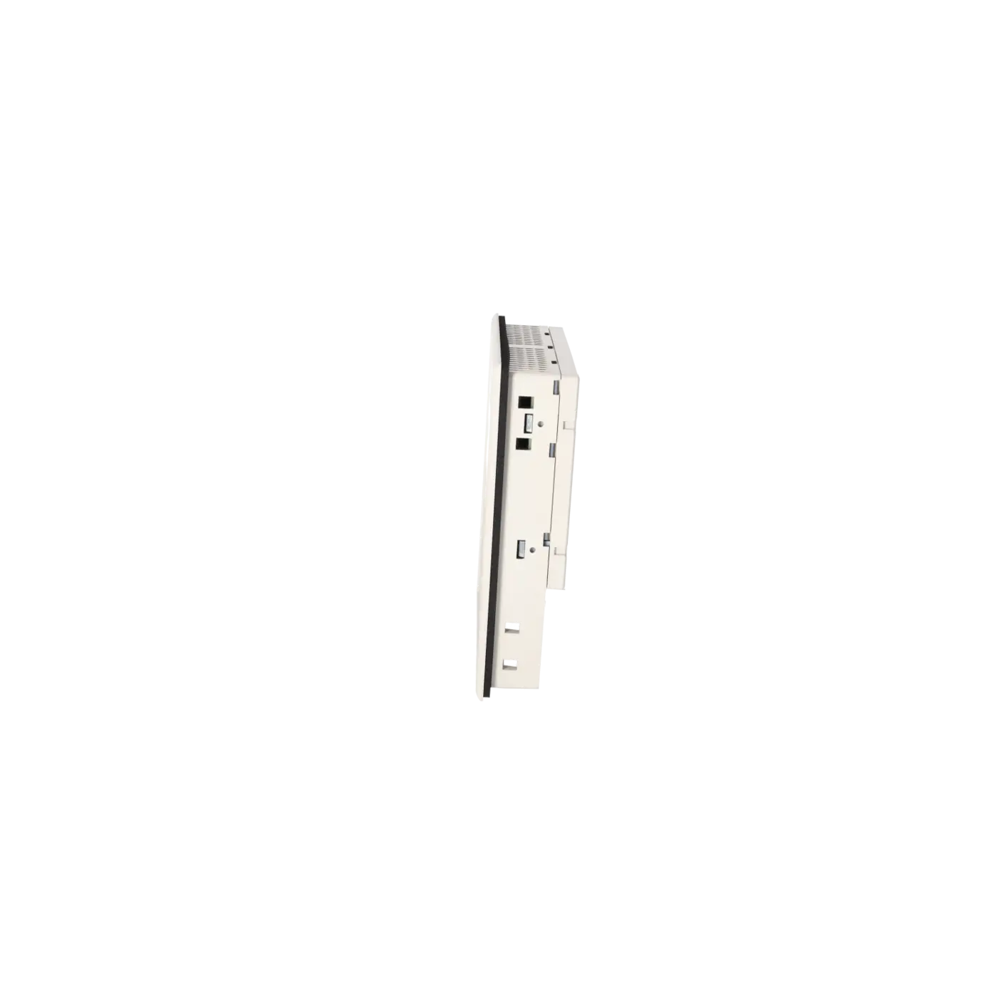
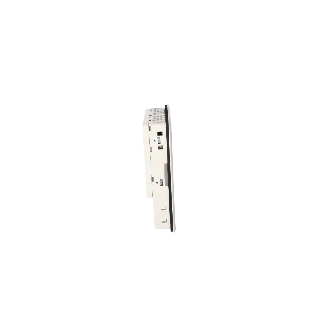
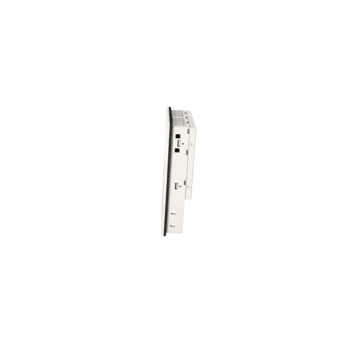
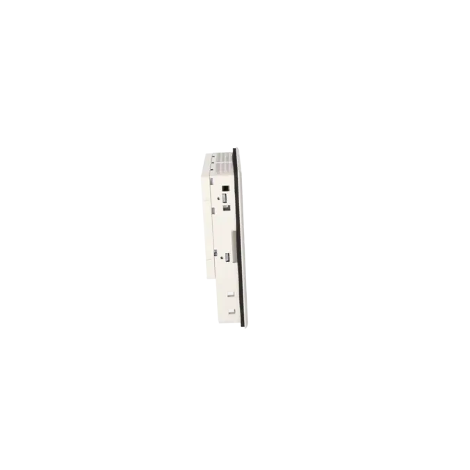
The defining technical characteristics include a 24 V DC power supply, a nominal current consumption of approximately 0.19 A, TTY, RS232, RS422 and RS485 communication interfaces, IP65 protection at the front and IP20 at the rear, compact dimensions of 144 × 180 × 38.5 mm and a low weight of approximately 0.43 kg. The black-and-white LC display is neither graphical nor touch-enabled. Instead, the device is designed for robust and straightforward text-based operation in traditional machine interfaces. Additional features include 8 function keys, 4 of which are equipped with LEDs, and a specified backlight MTBF of 100,000 hours at 25 °C. For project engineering and modifications, ProTool/Lite Version 2.51 or later is required. This is particularly important when existing projects need to be backed up, modified or migrated.
Product status, life-cycle status and obsolescence
The 6AV3607-1JC00-0AX1 is clearly an obsolete product. The EICHLER product page lists an EOP date of 2007-10-01. Siemens also classified the OP7/PP series as discontinued and removed from the active product range. In practice, this means that system availability now depends primarily on repair services, exchange units and tested used equipment rather than standard serial production. Historically, Siemens identified the OP 77A as the successor to the OP7/PP. Siemens migration documentation also refers to migration paths from the OP7 to the OP 77A or OP 77B. However, this should not be considered a direct 1:1 replacement, as project engineering, communication interfaces and functionality must be reviewed before migration.
The available EICHLER services and when they are relevant in practice
For operators of older installations, the services offered by EICHLER provide practical solutions for maintaining system availability. Repair is particularly suitable when the existing project configuration, wiring and installation arrangement should remain unchanged and preserving the original unit is the most economical option. Exchange units are especially valuable when production downtime must be minimised and rapid recovery is essential. Used devices are often attractive when budget constraints, spare parts strategies and short delivery times take priority over sourcing new equipment. New units are also available on request. According to the product page, repair, exchange and used equipment options are all associated with short turnaround or delivery times of 1–3 days. For discontinued HMIs, these service options help ensure continued operational reliability despite product obsolescence.
| Attribute | Value |
|---|---|
| Customer-specific configuration | No |
| Display | |
| Design of display | LC display, black/white |
| graphics-enabled | No |
| Line display | |
| ● Number of lines | 4 |
| ● Number of characters per line | 20 |
| Backlighting | |
| ● MTBF backlighting (at 25 °C) | 100 000 h |
| Control elements | |
| Control elements | Keys |
| Keyboard fonts | |
| ● Membrane keyboard | Yes |
| — user-definable label membrane keys | Yes |
| ● Function keys | |
| — Number of function keys | 8 |
| — Number of function keys with LEDs | 4 |
| ● System keys | |
| — Number of system keys | 22 |
| ● Numeric keyboard | Yes |
| ● alphanumeric keyboard | Yes |
| ● hexadecimal keyboard | Yes |
| ● Multi-key operation | No |
| Touch operation | |
| ● Design as touch screen | No |
| Installation type/mounting | |
| Mounting position | vertical |
| maximum permissible angle of inclination without external ventilation | 90° |
| Supply voltage | |
| Type of supply voltage | 24 V DC |
| UPS connectable (serial) | No |
| Input current | |
| Current consumption (rated value) | 0.19 A |
| Processor | |
| Processor type | X86 |
| Drives | |
| Diskette drive | Yes |
| CD-ROM | No |
| Hard disk | No |
| Memory | |
| Type of memory | Flash / RAM |
| Memory available for user data | 128 kbyte |
| Type of output | |
| Info LED | Yes |
| Power LED | No |
| Error LED | No |
| Time of day | |
| Clock | |
| ● Type | Software clock, synchronizable, no battery backup |
| ● retentive | No |
| ● synchronizable | Yes |
| Interfaces | |
| Interfaces/bus type | 1x TTY, 1x RS 232, 1x RS 422, 1x RS 485 |
| Number of RS 485 interfaces | 1 |
| Number of parallel interfaces | 0 |
| USB port | No |
| PC card slot | No |
| CF card slot | No |
| Special interfaces | No |
| With software interfaces | No |
| Degree and class of protection | |
| IP (at the front) | IP65 |
| IP (rear) | IP20 |
| Standards, approvals, certificates | |
| Certificate of suitability | CE, GL, BV, DNV, LRS, PRS, FM Class I Div. 2, UL, CSA, cULus, EX zone 2/22 |
| Ambient conditions | |
| Ambient temperature during storage/transportation | |
| ● min. | -25 °C |
| ● max. | 70 °C |
| Relative humidity | |
| ● Operation, max. | 95 % |
| Operating systems | |
| pre-installed operating system | Rmos |
| Configuration | |
| Message indicator | Yes |
| Alarm system (incl. buffer and acknowledgment) | Yes |
| Process value display (output) | No |
| Process value default (input) possible | No |
| Recipe management | Yes |
| Configuration software | |
| ● Configuration tool | ProTool / Lite Version 2.51 or higher (to be ordered separately) |
| Peripherals/Options | |
| Additional software components loadable | No |
| Dimensions | |
| Width of the housing front | 144 mm |
| Height of housing front | 180 mm |
| Overall depth | 38.5 mm |
| Weights | |
| Weight (without packaging) | 0.43 kg |
| Fault description | Possible solution |
|---|---|
| Why does my OP7/PP display message $115 “Establishing logical connection to the controller”? | This message indicates that the panel is establishing a logical connection to the controller or that the connection cannot be established reliably. First check the interface type, protocol parameters, address settings, cable wiring and grounding connection. Siemens also notes that error 115 can occur even when the physical connection is intact if the PLC cycle time is very short and the life-bit monitoring value is configured too aggressively. In such cases, the permissible monitoring value should be increased. During transfer and communication troubleshooting, defective GND connections within the communication cable have also been identified as a real-world cause. |
| Why does the OP7/PP report $613 “Data block not available or too short”? | Siemens clearly associates message 613 with a missing or insufficiently sized data block. Create the required data block in the PLC with the correct length and verify that the configured interface area, DB numbers, pointers and job mailboxes match the actual PLC structure. Ensure that reserved communication areas have not been overwritten or shortened. After correcting the PLC configuration, review the project settings and retransfer the project if necessary. |
| Why does the transfer from the PG/PC to the OP7/PP fail or why does the panel remain at “Ready for Transfer”? | In this state, the panel is waiting for data from the PG or PC. If the transfer process stalls, the transfer mode, serial interface settings, baud rate, cable wiring or project and firmware versions often do not match. Check the transfer settings in ProTool, select the correct COM port, verify the cable wiring including the GND connection and, if necessary, reduce the transmission speed for testing purposes. If the device displays “Firmware not compatible”, the project being transferred does not match the installed firmware or device platform. |
| Why is the display dark or difficult to read even though the OP7/PP starts up correctly? | First check the display contrast directly on the device using the SHIFT + / − key combination or through the standard system settings screen. Only after this should the power supply and hardware be evaluated. The OP7 operates on 24 V DC and uses LED backlighting; readability may decrease as the device ages. If additional messages such as “EPROM memory failure”, “RAM memory failure” or “Flash memory failure” are displayed, Siemens identifies memory or data transfer faults as likely causes. In such cases, retransferring the project or repairing the panel is the next logical step. |
Is the 6AV3607-1JC00-0AX1 still in the regular life cycle?
No. The device is listed with an EOP (End of Production) date of 2007-10-01, and Siemens classified the OP7/PP product range as discontinued. For procurement today, this means that maintaining system availability requires more than relying on new equipment alone. Repair services, exchange units and tested used devices should be considered as part of a long-term spare parts strategy. This is particularly important for purchasing and maintenance teams seeking to avoid unplanned downtime.
Which software is required for project engineering or modifications?
Siemens specifies ProTool/Lite Version 2.51 or later for the OP7/PP. This is important because many legacy installations can only be maintained properly using older engineering environments. For modernisation projects, migration also becomes a key consideration, as Siemens describes methods for continuing existing ProTool projects when migrating to newer operator panels within its WinCC flexible migration documentation. Before any service work is carried out, it is therefore advisable to determine whether the original project is available and which software version was used to create it.
Which controllers and communication interfaces are relevant for this panel?
The 6AV3607-1JC00-0AX1 variant is designed for SIMATIC S5 and SIMATIC 505 systems. Siemens specifies native drivers for these environments in the technical documentation. The communication manuals also describe the OP7/PP with the serial communication methods commonly used in legacy installations, including AS511 and FAP in S5 applications. In practice, this means that when ordering a replacement panel, it is not enough to verify the panel size alone. The communication method must also be checked carefully, as the interface type is often the deciding factor for compatibility in older systems.
Is there a Siemens successor to the OP7/PP?
Historically, Siemens identified the OP 77A as the successor to the OP7/PP. Siemens migration documentation also describes migration paths from the OP7 to the OP 77A or OP 77B. For system operators, this means that a successor can be identified, but the replacement should not be regarded as automatically functionally equivalent. Project engineering, operating logic, communication interfaces and, in some cases, installation and conversion requirements should all be reviewed beforehand to ensure that a replacement project does not become an unexpected retrofit under time pressure.
Are data retained after a power failure?
The OP7 operates without a battery. According to Siemens, operating data, excluding alarm buffer contents, are retained in flash memory. At the same time, the technical documentation specifies a software clock without battery backup. In practice, this means that project data and basic functionality are not automatically lost during a power failure, but buffered information and clock-related functions should be checked carefully during service activities. For legacy installations, this is particularly important when alarm histories or time-dependent records are expected to remain available after power has been restored.