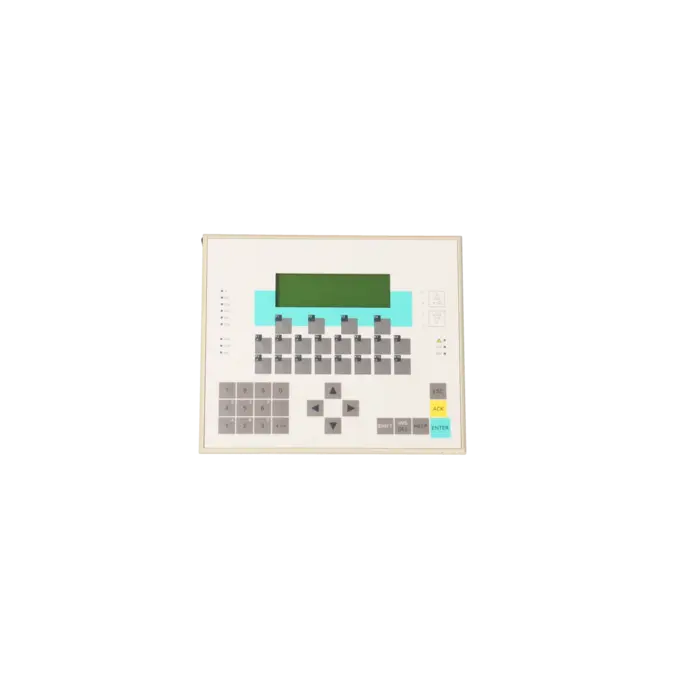
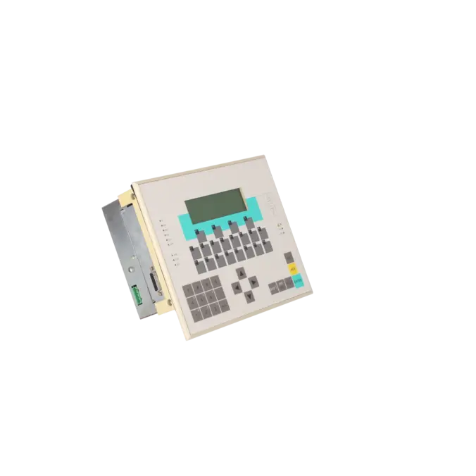
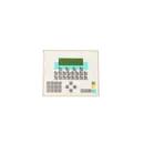
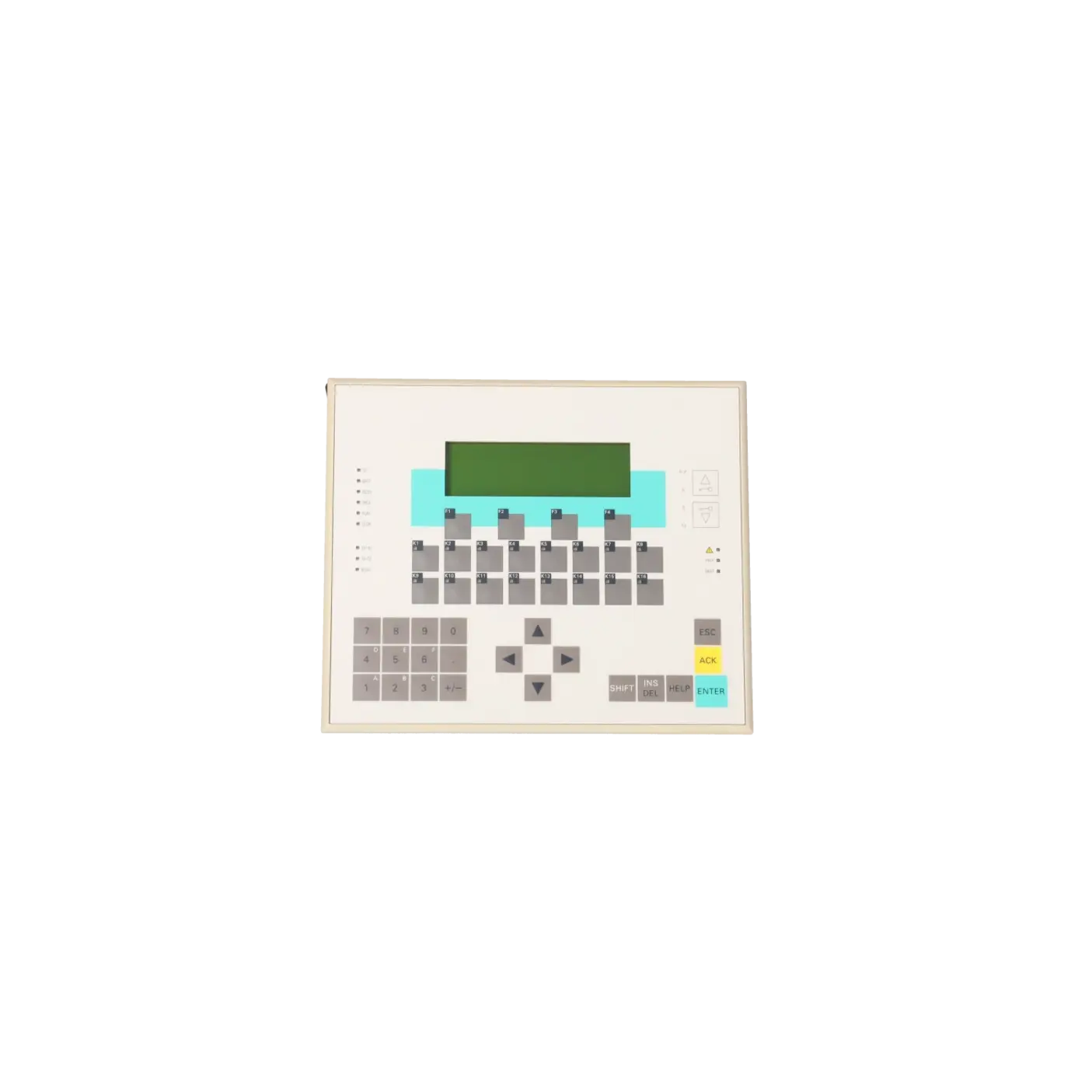
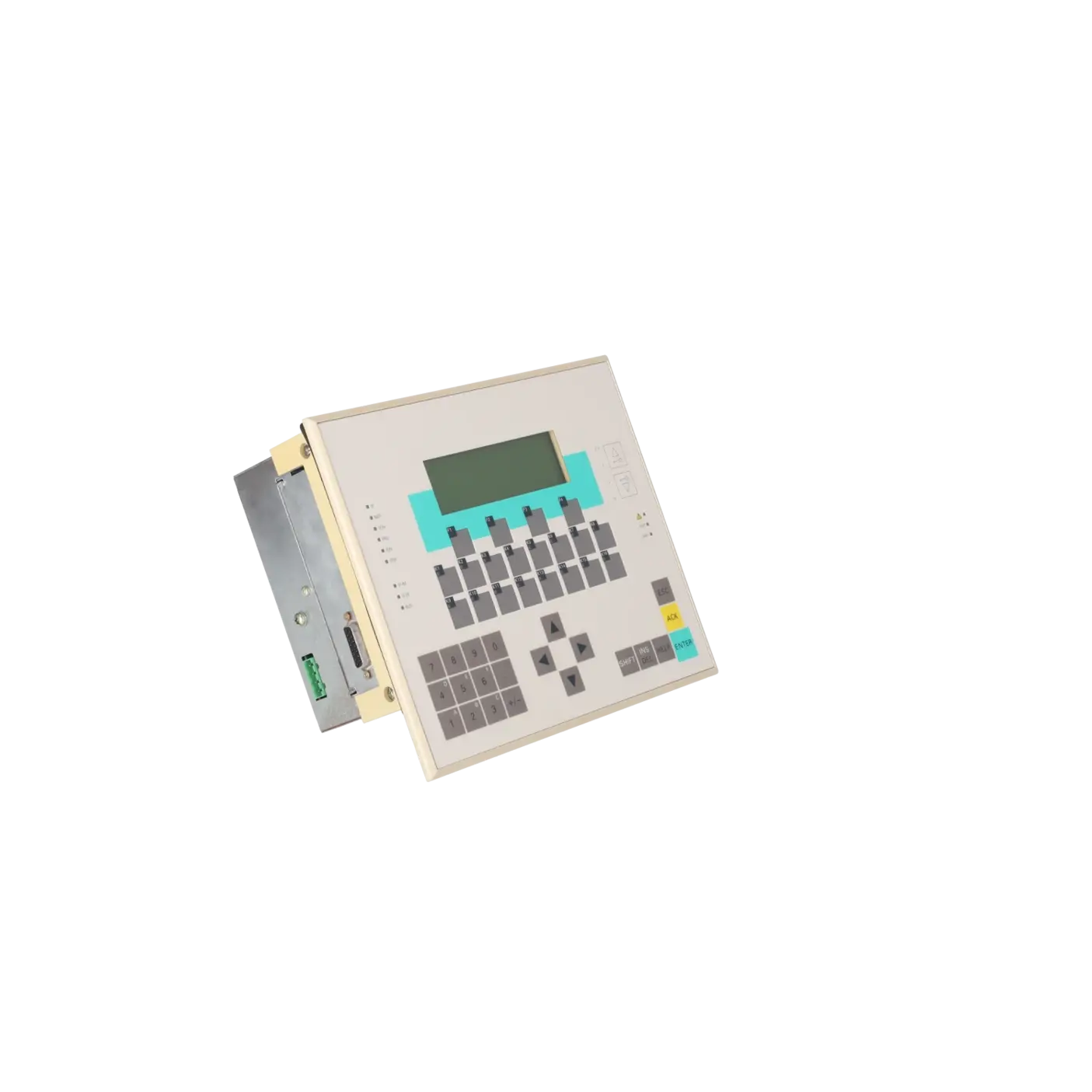
| Display |
|
| Design of display |
LCD backlit |
| Line display |
|
| ● Number of lines |
4 |
| ● Number of characters per line |
20 |
| ● Character size |
8 mm |
| Backlighting |
|
| ● MTBF backlighting (at 25 °C) |
100 000 h; about 11 years |
| Control elements |
|
| Keyboard fonts |
|
| ● Function keys |
|
| — Number of function keys |
16 |
| — Number of softkeys |
4 |
| Supply voltage |
|
| Rated value (DC) |
24 V |
| permissible range, lower limit (DC) |
20.4 V |
| permissible range, upper limit (DC) |
30.2 V |
| Load voltage L+ |
|
| ● Rated value (DC) |
24 V |
| ● permissible range, lower limit (DC) |
20.4 V |
| ● permissible range, upper limit (DC) |
28.8 V |
| Input current |
|
| Current consumption, typ. |
550 mA |
| Current consumption, max. |
1 A |
| Power loss |
|
| Power loss, typ. |
12 W |
| Memory |
|
| Work memory |
|
| ● integrated |
48 kbyte; 16 K instructions RAM |
| Load memory |
|
| ● expandable FEPROM |
Yes |
| ● expandable FEPROM, max. |
512 kbyte |
| ● integrated RAM, max. |
80 kbyte |
| Backup |
|
| ● present |
Yes |
| ● with battery |
Yes; all data |
| ● without battery |
Yes; 4 736 byte: parameterizable for memory bits, times, counters, data |
| CPU processing times |
|
| for bit operations, typ. |
0.3 µs |
| for bit operations, max. |
0.6 µs |
| for word operations, typ. |
1 µs |
| for fixed point arithmetic, typ. |
2 µs |
| for floating point arithmetic, typ. |
50 µs |
| for timer/counter operations, typ. |
12 µs |
| CPU-blocks |
|
| DB |
|
| ● Number, max. |
255; DB 0 reserved |
| FB |
|
| ● Number, max. |
192; see instruction list |
| FC |
|
| ● Number, max. |
192; see instruction list |
| OB |
|
| ● Number, max. |
see instruction list |
| ● Number of free cycle OBs |
1; OB 1 |
| ● Number of time alarm OBs |
1; OB 10 |
| ● Number of cyclic interrupt OBs |
1; OB 35 |
| ● Number of process alarm OBs |
1; OB 40 |
| ● Number of startup OBs |
1; OB 100 |
| ● Number of asynchronous error OBs |
7; OB 80, 81, 82, 85, 87, 121, 122 |
| Nesting depth |
|
| ● per priority class |
8 |
| Counters, timers and their retentivity |
|
| S7 counter |
|
| ● Number |
64 |
| Retentivity |
|
| — adjustable |
Yes |
| Counting range |
|
| — lower limit |
0 |
| — upper limit |
999 |
| S7 times |
|
| ● Number |
128 |
| Retentivity |
|
| — adjustable |
Yes |
| Time range |
|
| — lower limit |
10 ms |
| — upper limit |
9 990 s |
| Data areas and their retentivity |
|
| Flag |
|
| ● Size, max. |
256 byte |
| ● Retentivity available |
Yes |
| ● of which retentive with battery |
0 to 2047 |
| ● of which retentive without battery |
0 to 2047 |
| Address area |
|
| I/O address area |
|
| ● Inputs |
1 kbyte |
| ● Outputs |
1 kbyte |
| Process image |
|
| ● Inputs |
128 byte |
| ● Outputs |
128 byte |
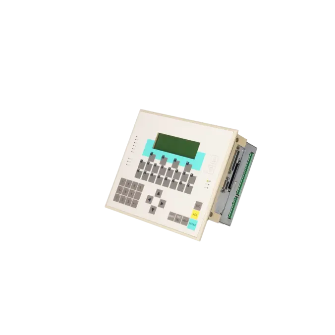
| Hardware configuration |
|
| connectable programming devices/PCs |
SIMATIC PG/PC, standard PC |
| Number of modules per system, max. |
8 |
| Number of modules per DP slave interface, max. |
32; 122 byte address space per DP station |
| Interface modules |
|
| ● Interface module IM 360 integrated |
Yes |
| Number of DP masters |
|
| ● integrated |
0 |
| ● via CP |
1; CP 342-5 |
| Number of operable FMs and CPs (recommended) |
|
| ● FM |
8 |
| ● CP, PtP |
4 |
| ● CP, LAN |
2 |
| Expansion modules |
|
| ● Analog inputs/outputs, max. |
192 |
| ● Digital inputs/outputs, max. |
768 |
| ● Number of expansion modules, max. |
24 |
| Rack |
|
| ● Modules per rack, max. |
8 |
| ● Number of lines, max. |
3 |
| Time of day |
|
| Clock |
|
| ● Hardware clock (real-time) |
Yes; CPU |
| ● Software clock |
Yes; OP |
| Digital inputs |
|
| Number of digital inputs |
16 |
| Number of universal inputs |
4 |
| ● usable as |
UI1, UI2: Digital/alarm input 24 V DC or up/down counter; UI3: Digital/alarm input 24 V DC or up/down counter or frequency/period duration counter; UI4: Digital/alarm input 24 V DC |
| Input voltage |
|
| ● Rated value (DC) |
24 V |
| ● for signal "0" |
-3 to +5V |
| ● for signal "1" |
+11 to +30V |
| Input current |
|
| ● for signal "1", typ. |
11.5 mA |
| Input delay (for rated value of input voltage) |
|
| for standard inputs |
|
| — at "0" to "1", max. |
4.8 ms; typically 3 ms |
| Cable length |
|
| ● shielded, max. |
1 000 m |
| ● unshielded, max. |
600 m |
| Digital outputs |
|
| Number of digital outputs |
16 |
| Short-circuit protection |
Yes; Clocked electronically |
| Limitation of inductive shutdown voltage to |
48 V |
| Switching capacity of the outputs |
|
| ● on lamp load, max. |
5 W |
| Output voltage |
|
| ● for signal "1", min. |
L+ (-0.8 V) |
| Output current |
|
| ● for signal "1" rated value |
0.5 A |
| ● for signal "1" minimum load current |
5 mA |
| ● for signal "0" residual current, max. |
0.5 mA |
| Switching frequency |
|
| ● with resistive load, max. |
100 Hz |
| ● with inductive load, max. |
0.5 Hz |
| Total current of the outputs (per group) |
|
| all mounting positions |
|
| — up to 20 °C, max. |
4 A |
| — up to 40 °C, max. |
2 A |
| Cable length |
|
| ● shielded, max. |
1 000 m |
| ● unshielded, max. |
600 m |
| Analog inputs |
|
| Number of analog inputs |
4 |
| permissible input voltage for voltage input (destruction limit), max. |
30 V |
| permissible input current for current input (destruction limit), max. |
30 mA |
| Cycle time (all channels), typ. |
2 ms |
| Input ranges |
|
| ● Voltage |
Yes |
| ● Current |
Yes |
| Input ranges (rated values), voltages |
|
| ● -10 V to +10 V |
Yes |
| — Input resistance (-10 V to +10 V) |
50 kΩ |
| Input ranges (rated values), currents |
|
| ● -20 mA to +20 mA |
Yes |
| ● 4 mA to 20 mA |
Yes |
| — Input resistance (4 mA to 20 mA) |
105.5 kΩ |
| Analog outputs |
|
| Number of analog outputs |
4 |
| Voltage output, short-circuit protection |
Yes |
| Voltage output, short-circuit current, max. |
25 mA |
| Current output, no-load voltage, max. |
16 V; ± |
| Cycle time (all channels) max. |
4 ms; typ. 2 ms |
| Output ranges, voltage |
|
| ● -10 V to +10 V |
Yes |
| Output ranges, current |
|
| ● -20 mA to +20 mA |
Yes |
| ● 4 mA to 20 mA |
Yes |
| Load impedance (in rated range of output) |
|
| ● with voltage outputs, min. |
2 kΩ |
| ● with voltage outputs, capacitive load, max. |
1 µF |
| ● with current outputs, max. |
0.5 kΩ |
| ● with current outputs, inductive load, max. |
1 mH |
| Cable length |
|
| ● shielded, max. |
200 m |
| Analog value generation for the inputs |
|
| Integration and conversion time/resolution per channel |
|
| ● Resolution with overrange (bit including sign), max. |
12 bit |
| Analog value generation for the outputs |
|
| Integration and conversion time/resolution per channel |
|
| ● Resolution with overrange (bit including sign), max. |
12 bit |
| ● Conversion time (per channel) |
0.5 ms |
| Settling time |
|
| ● for resistive load |
0.1 ms |
| ● for capacitive load |
3.3 ms |
| ● for inductive load |
0.5 ms |
| Encoder |
|
| Connectable encoders |
|
| ● 2-wire sensor |
Yes |
| — permissible quiescent current (2-wire sensor), max. |
2 mA |
| Errors/accuracies |
|
| Operational error limit in overall temperature range |
|
| ● Voltage, relative to input range, (+/-) |
0.8 % |
| ● Current, relative to input range, (+/-) |
0.8 % |
| ● Voltage, relative to output range, (+/-) |
0.8 % |
| ● Current, relative to output range, (+/-) |
1 % |
| Basic error limit (operational limit at 25 °C) |
|
| ● Voltage, relative to input range, (+/-) |
0.6 % |
| ● Current, relative to input range, (+/-) |
0.6 % |
| ● Voltage, relative to output range, (+/-) |
0.5 % |
| ● Current, relative to output range, (+/-) |
0.6 % |
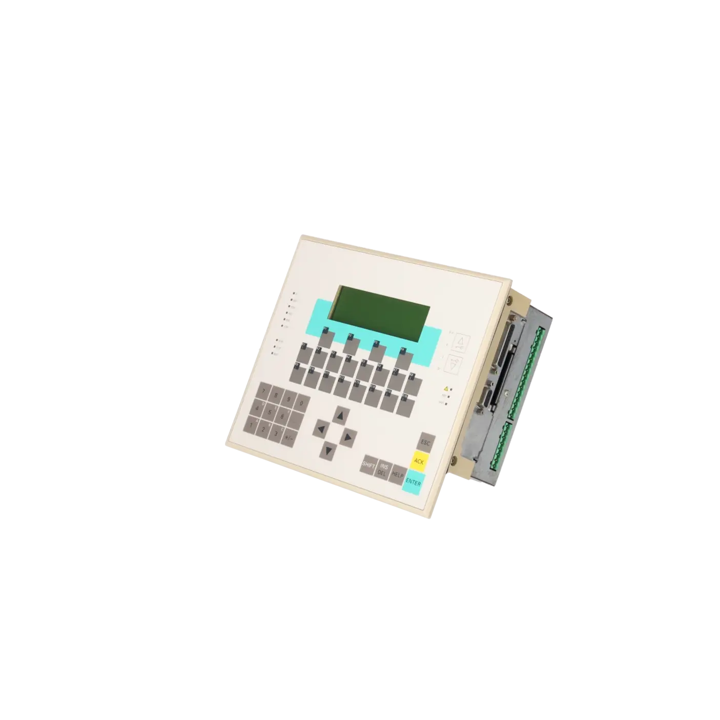
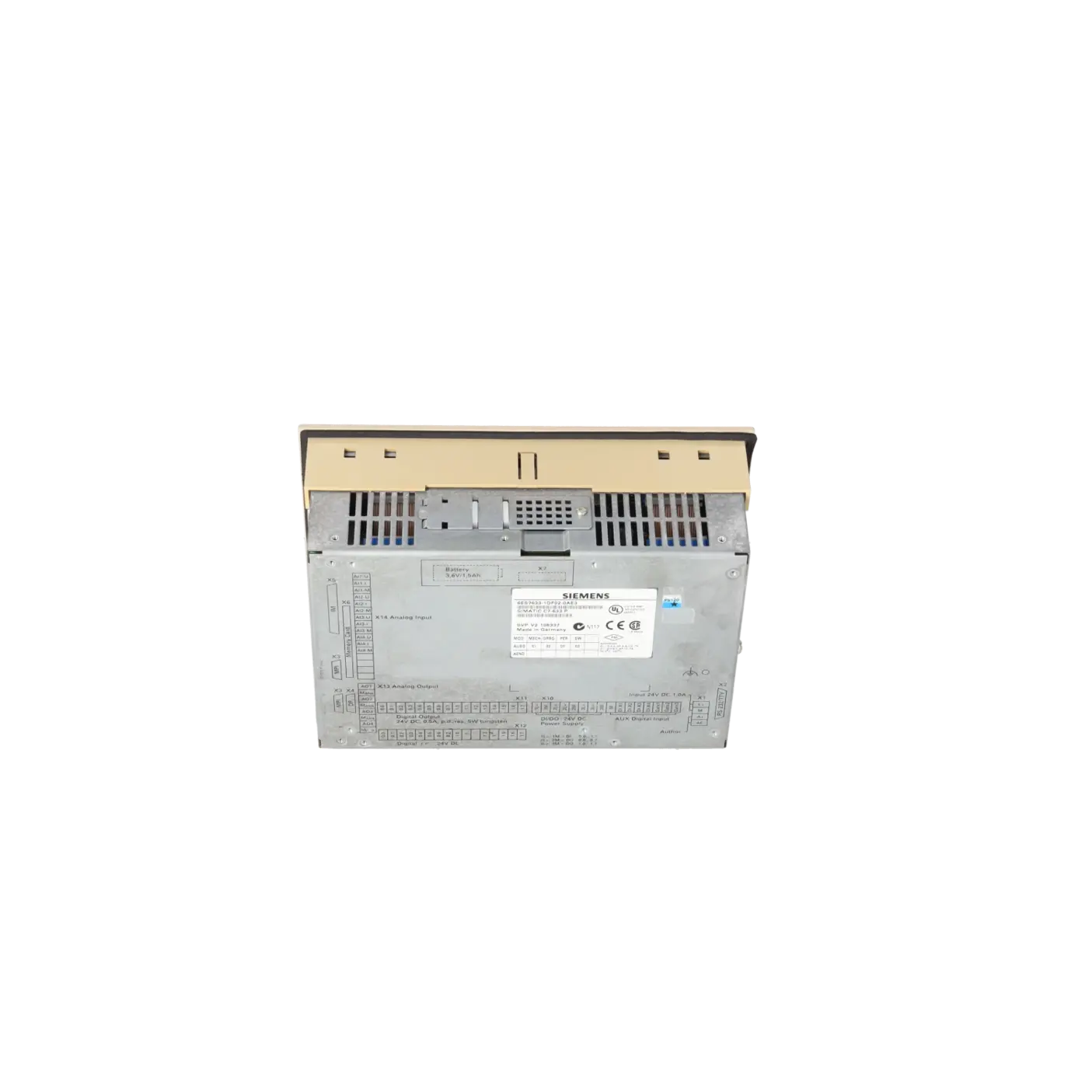
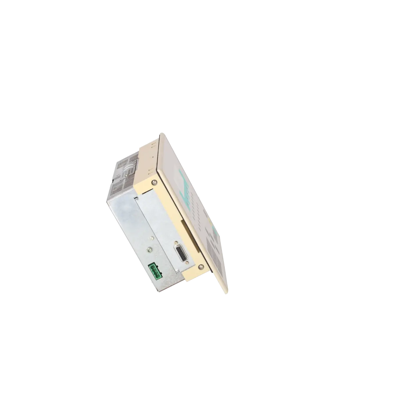
| Interfaces |
|
| Number of printer interfaces |
1; RS 232 |
| MPI |
|
| ● Cable length, max. |
9 100 m; without repeaters 50 m; with 2 repeaters: 1100 m; with 10 repeaters in series: 9100 m; via fiber optic cable: 23.8 km (with star hubs or OLMs) |
| 1. Interface |
|
| Protocols |
|
| ● MPI |
Yes; occupies 2 nodes per device (1 x CPU, 1 x OP) |
| ● PROFIBUS DP master |
No |
| ● PROFIBUS DP device |
No |
| MPI |
|
| ● Number of nodes, max. |
32; PG/PC, OP, C7, S7-300/400, M7 |
| ● Transmission rate, max. |
187.5 kbit/s |
| communication functions / header |
|
| S7 communication |
|
| ● S7 extended communication |
Yes; Server |
| S5 compatible communication |
|
| ● supported |
Yes |
| Standard communication (FMS) |
|
| ● supported |
Yes |
| Number of connections |
|
| ● overall |
|
| — of which dynamic |
8 |
| — of which static |
4 |
| Interrupts/diagnostics/status information |
|
| Diagnostics function |
Yes; C7-CPU |
| Substitute values connectable |
Yes; Parameterizable |
| Alarms |
|
| ● Alarm cycle |
Yes; Parameterizable |
| ● Diagnostic alarm |
Yes; Measurement overrange, wire break detection at 4 to 20 mA by means of software; parameterizable for parameter errors |
| Counter |
|
| Number of counter inputs |
3; UE1, UE2, UE3 |
| Principle |
Counting of edges |
| Counting range, description |
UI1, UI2: up: 0 to 65535, down: 65535 to 0; UI3: up: 0 to 16777215, down: 16777215 to 0 |
| Counter frequency, max. |
10 kHz |
| Counting alarm backward counter |
on reaching "0" |
| Counting alarm forward counter |
on reaching limit value |
| Enable |
In the program |
| Limit value (setpoint) default |
one counter per value |
| External gate counters |
|
| ● Number of external gate counters |
3 |
| ● Principle |
Counting of edges within a gate time via external pin |
| ● Counting range |
UE1, UE2: 0 to 65535; UE3: 0 to 16777215 |
| Frequency counter |
|
| ● Number |
1; UI3 |
| ● Principle |
Counting of pulses within a time period |
| ● Gate width, adjustable |
Yes |
| ● Gate width |
0.1 / 1 / 10 s (adjustable) |
| ● Counting range |
0 to 16777215 |
| Cycle duration counter |
|
| ● Number |
1; UI3 |
| ● Cycle duration, max. |
8.38 s; or 0.12 Hz |
| ● Principle |
Counting of fixed time units between two positive edges |
| ● Counting range, lower limit |
0 |
| ● Counting range, upper limit |
16 777 214 |
| Potential separation |
|
| Potential separation digital inputs |
|
| ● Potential separation digital inputs |
Yes; Optocoupler |
| ● between the channels, in groups of |
16 |
| Potential separation digital outputs |
|
| ● Potential separation digital outputs |
Yes; Optocoupler |
| ● between the channels, in groups of |
8 |
| Potential separation analog inputs |
|
| ● Potential separation analog inputs |
Yes; shared with AO |
| Potential separation analog outputs |
|
| ● Potential separation analog outputs |
Yes; shared with AI |
| Potential separation channels |
|
| ● Potential separation universal inputs |
No |
| Isolation |
|
| Isolation tested with |
500 V DC |
| EMC |
|
| EMC interference immunity |
Noise immunity: IEC 1000-4-2, IEC 1000-4-3, IEC 1000-4-4, IEC 1000-4-6, EN 50140 |
| Emission of radio interference acc. to EN 55 022 |
|
| ● Interference emission acc. to EN 55022, class A |
Yes; Noise emission: Class A / EN 55022; conducted interference: IEC 1000-4-4, IEC 1000-4-5 |
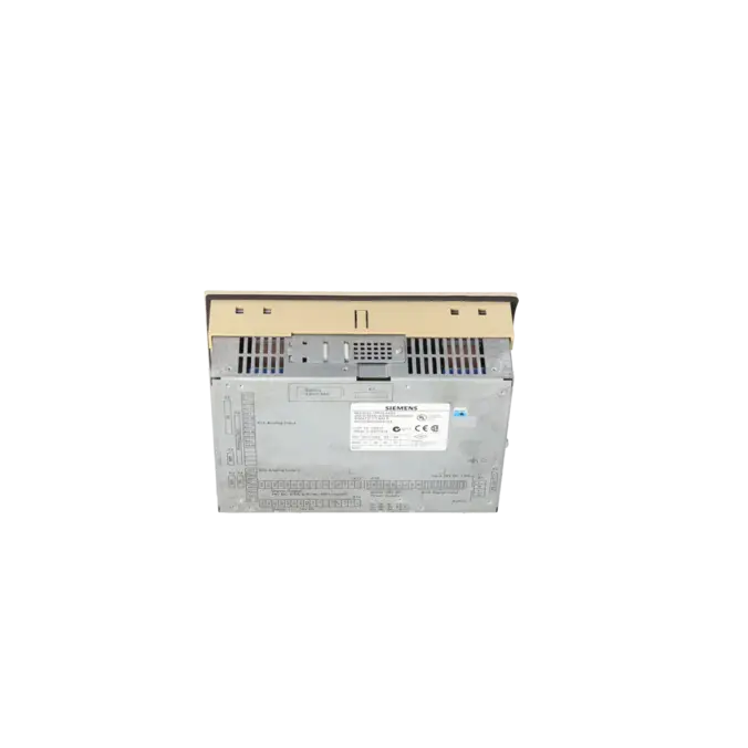
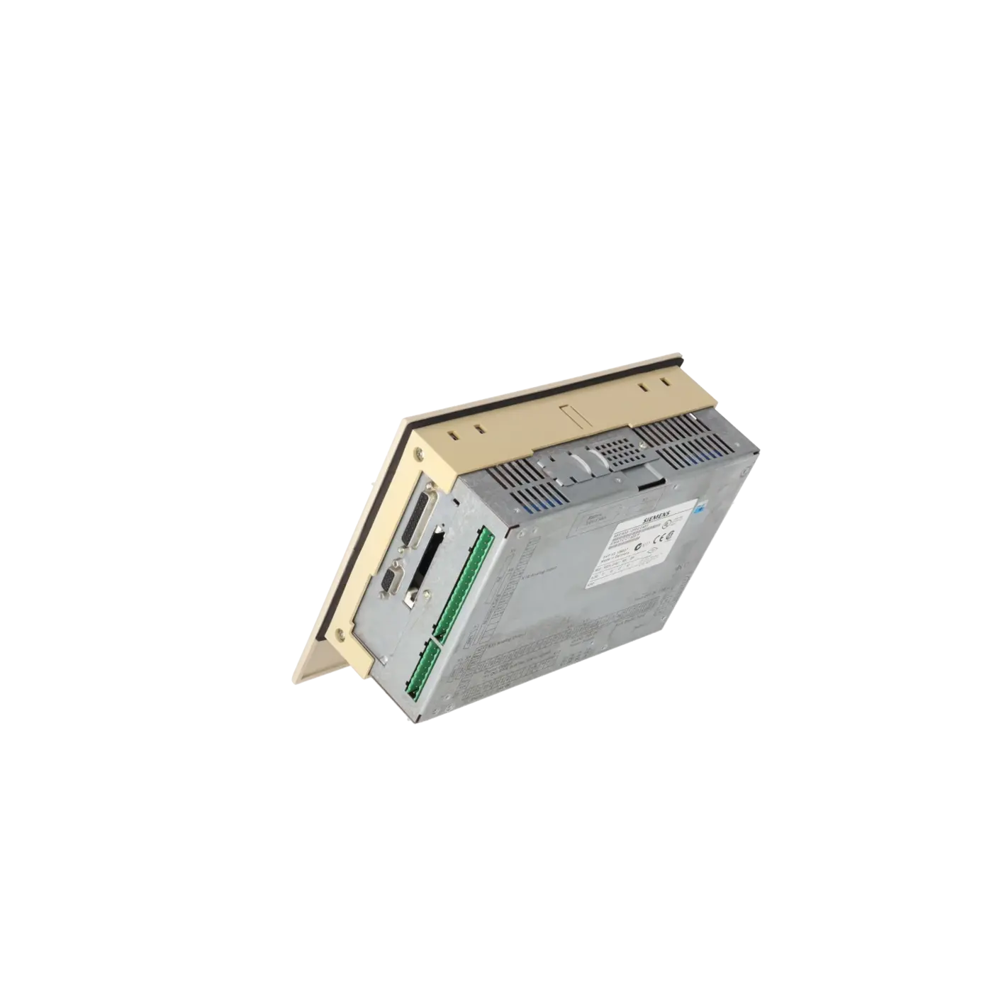
| Degree and class of protection |
|
| IP (at the front) |
IP65 |
| IP (rear) |
IP20 |
| Standards, approvals, certificates |
|
| CSA approval |
Yes; to Standard C22.2 number 142 |
| UL approval |
Yes; UL 508 |
| FM approval |
Yes; FM-Standards No. 3611, 3600, 3810 Class I, Division 2, Group A, B, C, D |
| developed in accordance with IEC 61131 |
Yes; EN 61131-2 (IEC 1131-2) |
| DIN/ISO 9001 |
Yes |
| Ambient conditions |
|
| Ambient temperature during operation |
|
| ● vertical installation, min. |
0 °C |
| ● vertical installation, max. |
50 °C |
| Air pressure acc. to IEC 60068-2-13 |
|
| ● permissible range, lower limit |
795 hPa |
| ● permissible range, upper limit |
1 080 hPa |
| Relative humidity |
|
| ● Operation, min. |
5 % |
| ● Operation, max. |
95 %; no condensation |
| Vibrations |
|
| ● Operation, tested according to IEC 60068-2-6 |
Yes; IEC 60068-2-6; 10 Hz to 58 Hz; (constant amplitude 0.075 mm); 58 Hz to 500 Hz; (constant acceleration 9.8 m/s²) |
| Shock testing |
|
| ● tested according to IEC 60068-2-29 |
Yes; IEC 68, Part 2-29 half-sine: 100 m/s² (10 g), 16 ms, 100 shocks |
| configuration / header |
|
| Configuration software |
|
| ● STEP 7 |
Yes |
| ● STEP 7 Lite |
Yes |
| ● ProTool |
Yes |
| ● ProTool/Lite |
Yes |
| ● ProTool/Pro |
Yes |
| configuration / programming / header |
|
| ● Command set |
see instruction list |
| ● Nesting levels |
8 |
| ● Program organization |
Linear, structured |
| ● System functions (SFC) |
see instruction list |
| Programming language |
|
| — LAD |
Yes |
| — FBD |
Yes |
| — STL |
Yes |
| — SCL |
Yes |
| — CFC |
Yes |
| — GRAPH |
Yes |
| — HiGraph® |
Yes |
| Software libraries |
|
| — Process diagnostics |
Yes; C7-CPU |
| — Software controller |
Yes; 16 circles |
| Know-how protection |
|
| ● User program protection/password protection |
Yes |
| — Password levels |
9 |
| programming / cycle time monitoring / header |
|
| ● lower limit |
1 ms |
| ● upper limit |
6 000 ms |
| ● adjustable |
Yes |
| ● preset |
150 ms |
| Languages |
|
| Online languages |
|
| ● Number of online/runtime languages |
3 |
| Functionality under WinCC (TIA Portal) |
|
| Message system |
|
| ● Number of messages |
499 |
| ● Number of process values per message |
8 |
| Recipe management |
|
| ● Number of recipes |
99 |
| ● Data records per recipe |
99 |
| ● Entries per data record |
99 |
| ● recipe memory, max. |
4 kbyte |
| Images |
|
| ● Number of configurable images |
99 |
| Image objects |
|
| ● Number of I/O fields per image |
99 |
| ● Graphics object |
|
| — Character graphics |
Yes; As part of the character set |
| Complex image objects |
|
| ● dynamic objects |
Input, output, input/output fields, date/time fields, symbolic input/output fields |
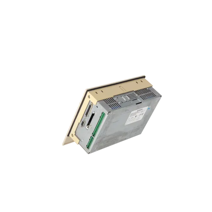
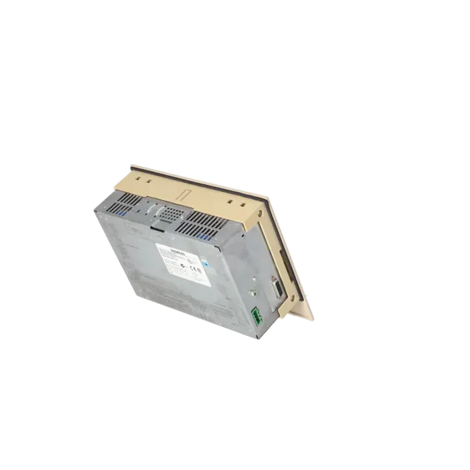
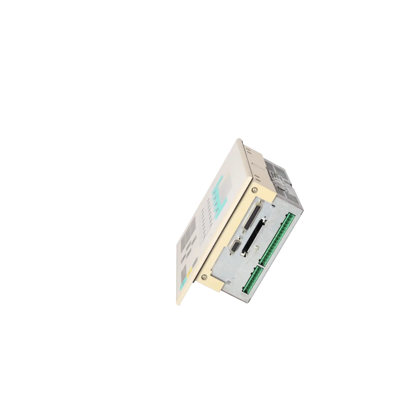
| Dimensions |
|
| Width |
240 mm |
| Height |
203.5 mm |
| Depth |
90 mm |
| Mounting cutout, width |
231 mm |
| Mounting cutout, height |
159 mm |
| Weights |
|
| Weight, approx. |
1 800 g |