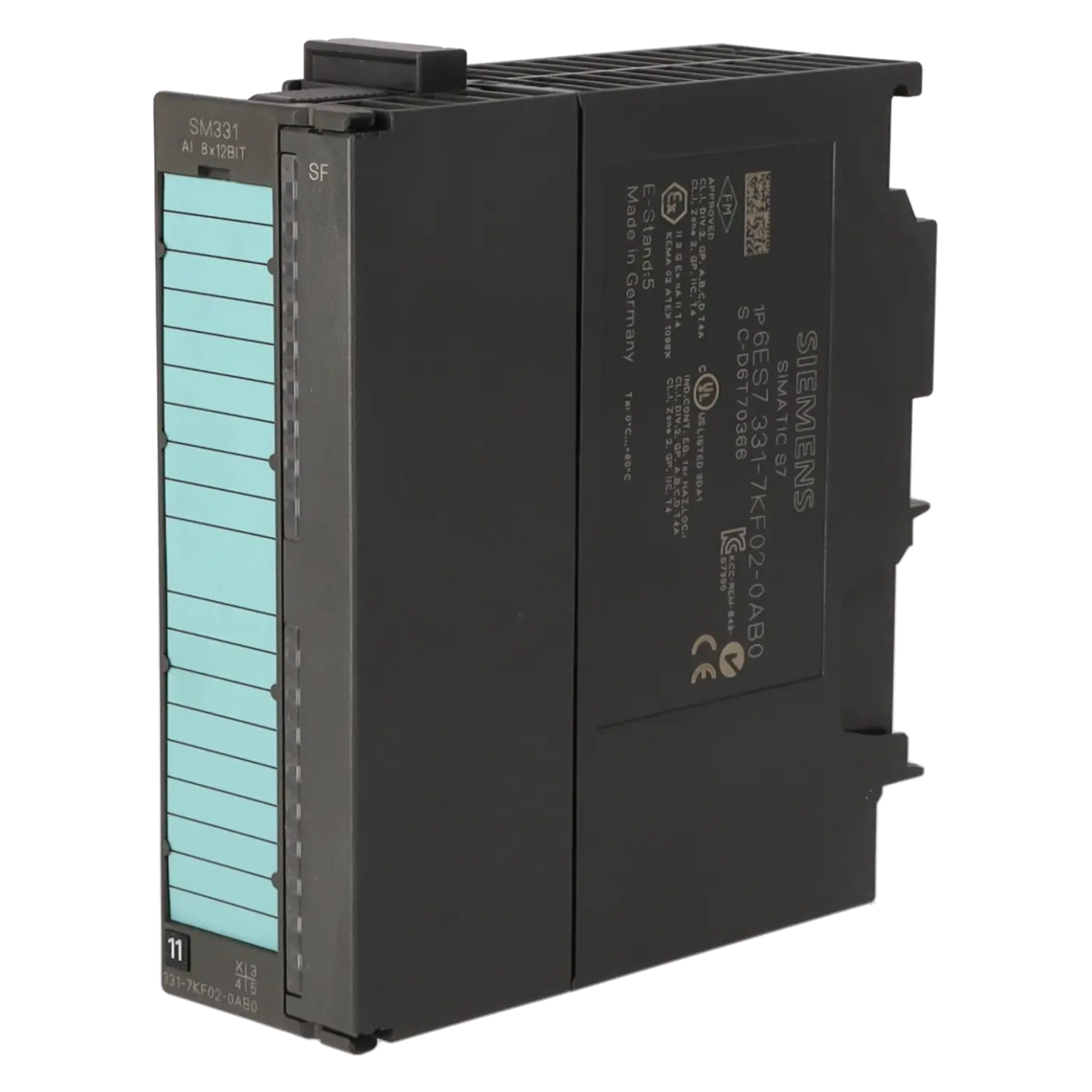
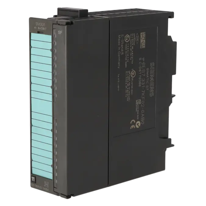


SIEMENS 6ES7331-7KF02-0AB0
-
SIEMENS | PLC Controls | Analog Input / Output Modules
- EICHLER-art.no.: K0118575
- EAN: 4025515066835
- UPC: 662643177909
Product description
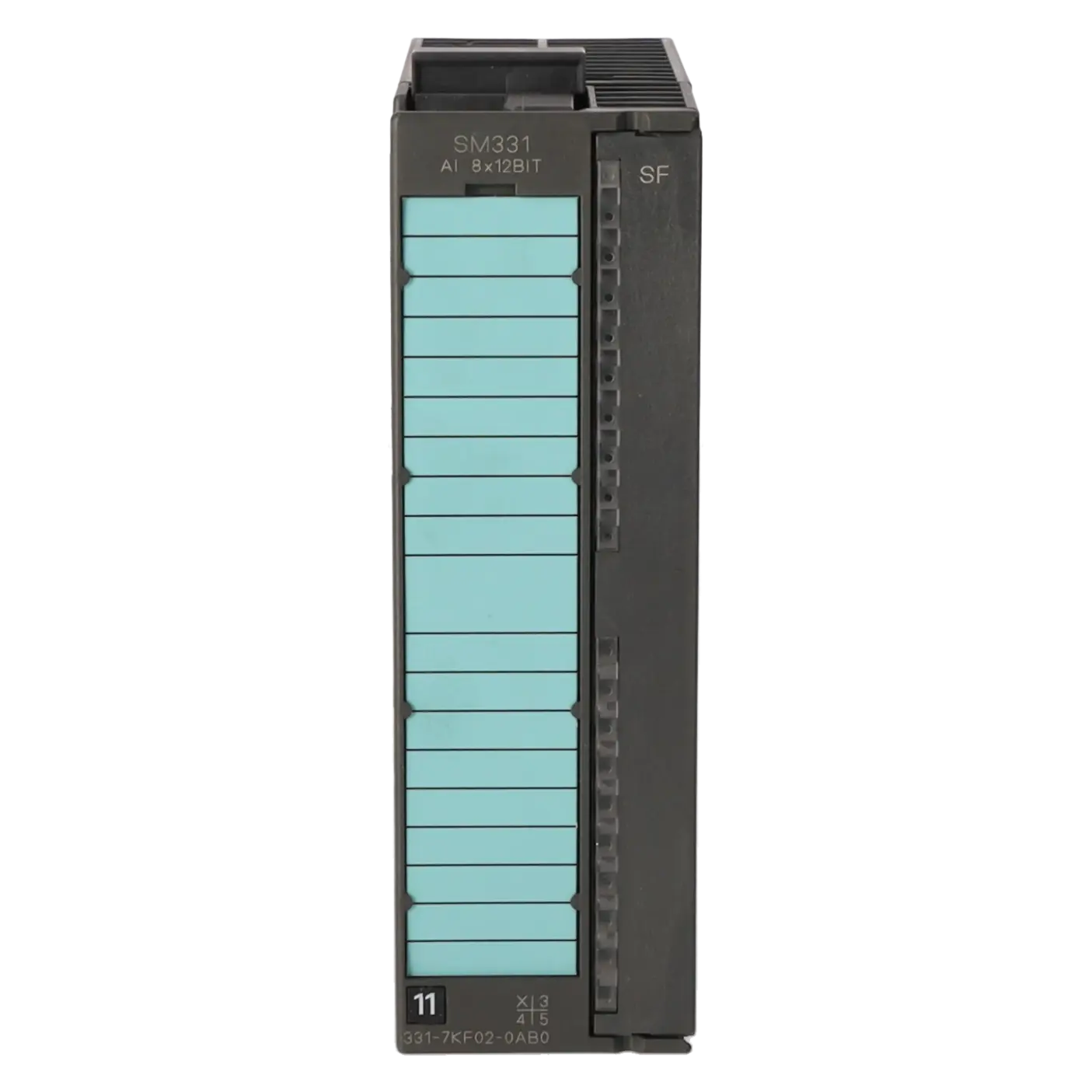
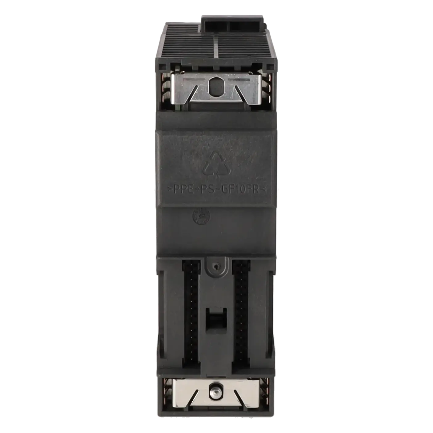
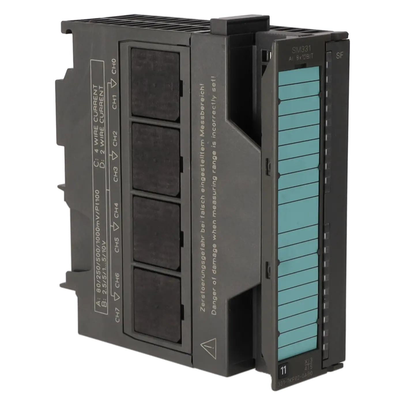
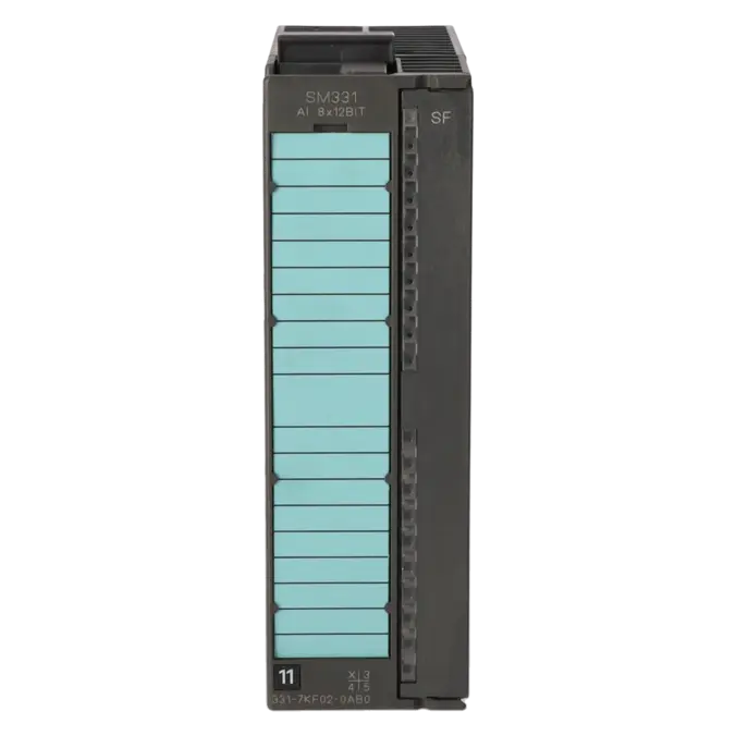
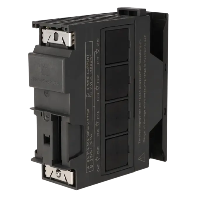
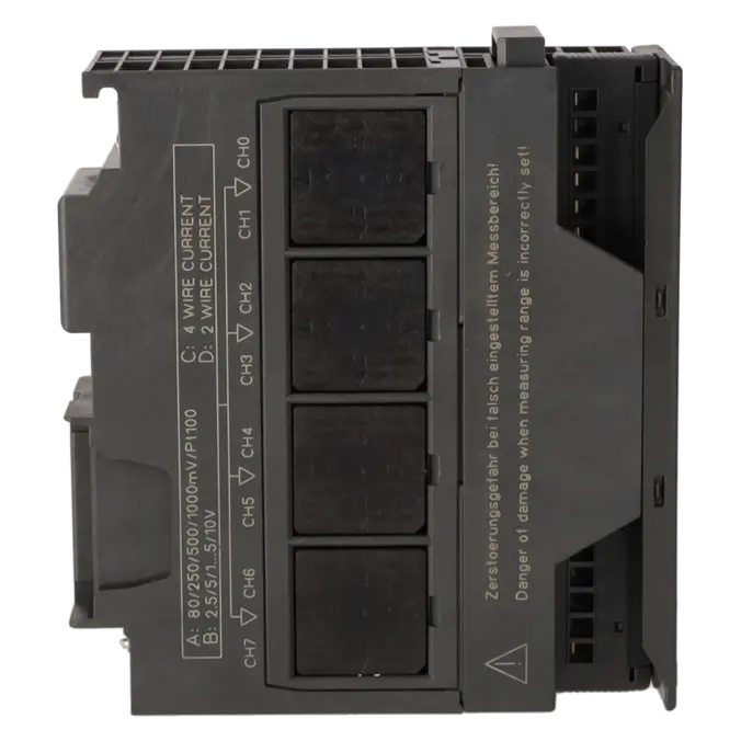
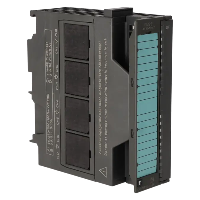
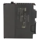
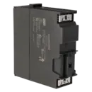
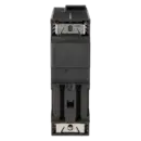
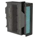
SIMATIC S7-300, ANALOG INPUT SM 331, ISOLATED, 8 AI, RESOLUTION 9/12/14 BITS, U/I/THERMOCOUPLE/RESISTOR, ALARM, DIAGNOSTICS, 1X 20-POLE REMOVING/INSERTING WITH ACTIVE BACKPLANE BUS
Services for SIEMENS 6ES7331-7KF02-0AB0
Repair
from 475,36 €
to 855,64 €
Replacement
1.021,08 €
765,81 €
Used
1.134,55 €
850,91 €
New
1.260,60 €
945,45 €
SIEMENS |
6ES7331-7KF02-0AB0 –
additional product information
| Delivery information | |||
|---|---|---|---|
| Export identifier | AL: N ECCN: EAR99H | ||
| Net weight | 0.288 | ||
| Quantity | 1 Stück | ||
| Packaging quantity | 1 | ||
| Additional product information | |||
|---|---|---|---|
| Product status | EOP: 2025-10-01 | ||
| EAN | 4025515066835 | ||
| UPC | 662643177909 | ||
| Static lot number | 85389091 | ||
| List indicator | ST73 | ||
| Product group | 4561 | ||
| Country of origin | DE | ||
| Compliance with the substance restrictions according to RoHS directive | Since: 20080331 | ||
| Product classifications | Version | Classification | |
|---|---|---|---|
| eClass | 4 | 27-24-03-05 | |
| eClass | 5.1 | 27-24-22-01 | |
| eClass | 6.0 | 27-24-22-01 | |
| ETIM | 3 | / | |
| ETIM | 4 | EC001420 | |
| ETIM | 5 | EC001420 | |
Was ist 6ES7331-7KF02-0AB0 und wo wird es eingesetzt
Die 6ES7331-7KF02-0AB0 ist eine SIMATIC S7-300 Analogue Input Module SM 331 von Siemens. Die Baugruppe ist für Anlagen ausgelegt, in denen unterschiedliche analoge Sensorsignale zuverlässig in die SPS eingebunden werden müssen. Typische Einsatzfelder sind mechanical engineering, process plants, furnace and temperature control systems, utilities infrastructure sowie brownfield installations mit S7-300 oder verteilten ET 200M-Strukturen. Besonders relevant ist das Modul dort, wo die bestehende Feldverdrahtung erhalten bleiben soll und ein 1:1 replacement ohne größere Umbauten benötigt wird. Für Instandhalter ist die Baugruppe interessant, weil sie voltage, current, thermocouple und resistance-based signals verarbeiten kann und dadurch zahlreiche Messaufgaben mit nur einem Modultyp abdeckt.
Überblick der wichtigsten technischen Daten und was diese bedeuten
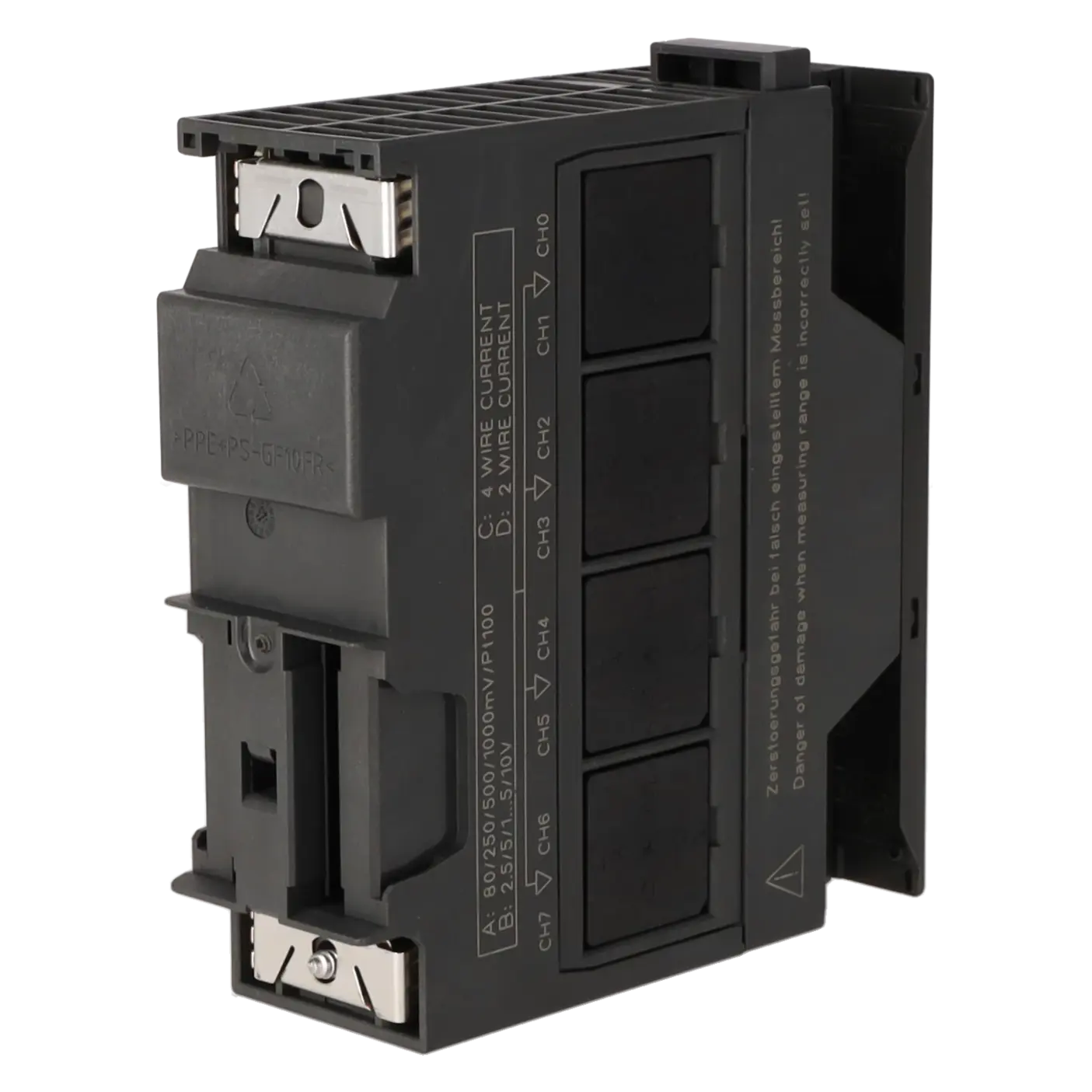
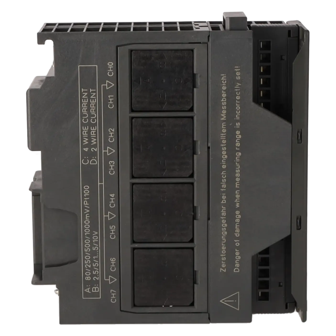
Die Baugruppe arbeitet mit einer 24 V DC load supply, verfügt über 8 analogue inputs und unterstützt je nach Messaufgabe eine Auflösung von 9, 12 or 14 bits. Das bedeutet: Je höher die parametrierte Auflösung und Integrationszeit, desto präziser die Messung, allerdings steigt auch die Wandlungszeit. Unterstützt werden voltage signals, current signals including 4…20 mA, thermocouples type E, J, K, L and N, Pt100/Ni100 sensors sowie 150/300/600 Ω resistance measurements. Wichtig für die Praxis: Bei der Widerstandsmessung stehen effektiv 4 measuring channels zur Verfügung. Das Modul bietet parameterisable diagnostic and limit-value alarms, eine red SF LED zur Fehleranzeige, einen 20-pin front connector sowie Abmessungen von 40 × 125 × 117 mm. Die electrical isolation besteht gegenüber dem Backplane Bus und der Elektronikversorgung, jedoch nicht zwischen den einzelnen Kanälen.
Produktstatus, Life-Cycle-Status und Obsoleszenz
Für Beschaffung und Bestandsstrategie ist der Produktlebenszyklus besonders wichtig. Siemens führt die 6ES7331-7KF02-0AB0 aktuell als spare part, während auf der EICHLER-Produktseite zusätzlich der Produktstatus EOP: 2025-10-01 genannt wird. Dies weist klar auf eine Baugruppe im late lifecycle stage hin, die in Bestandsanlagen weiterhin benötigt wird, deren Versorgung jedoch aktiv abgesichert werden sollte. Ein von Siemens dokumentierter kompatibler Nachfolger für die älteren Varianten 6ES7331-7KF01-0AB0 und 6ES7331-7KF00-0AB0 ist genau dieses Modul, also die 6ES7331-7KF02-0AB0. Für die hier betrachtete Baugruppe selbst wird in den öffentlich verfügbaren Produktunterlagen kein allgemeiner direct 1:1 successor genannt. Im Rahmen von ET-200M-zu-ET-200SP-HA-Migrationen verweist Siemens je nach Messart auf Ersatzkonzepte rund um die 6DL1134-6AF00-0PH1.
Verfügbare EICHLER Leistungen und wann diese relevant sind
Für Betreiber älterer S7-300- oder ET-200M-Anlagen sind die verfügbaren Leistungen insbesondere dann relevant, wenn Stillstände vermieden und vorhandene Baugruppen wirtschaftlich weiter genutzt werden sollen. Eine repair ist sinnvoll, wenn die vorhandene Karte mechanisch und funktional grundsätzlich zur Anlage passt und die Wiederherstellung der Originalbaugruppe die schnellste oder risikoärmste Lösung darstellt. EICHLER nennt hierfür 2–5 days turnaround time und beschreibt die Leistung mit technical cleaning, preventive maintenance, comprehensive functional testing sowie mindestens 24 months warranty. Exchange, used und new units sind vor allem dann interessant, wenn die schnellstmögliche Wiederverfügbarkeit im Vordergrund steht; diese Varianten werden aktuell mit 1–3 days availability angegeben. Das optionale test report for analogue inputs/outputs ist besonders für qualitätskritische Prozesse, Dokumentationspflichten und Abnahmen von Vorteil.
| Attribute | Value |
|---|---|
| General information | |
| Product function | |
| ● Isochronous mode | No |
| Supply voltage | |
| Load voltage L+ | |
| ● Rated value (DC) | 24 V |
| ● Reverse polarity protection | Yes |
| Input current | |
| from load voltage L+ (without load), max. | 30 mA |
| from backplane bus 5 V DC, max. | 50 mA |
| Power loss | |
| Power loss, typ. | 1 W |
| Analog inputs | |
| Number of analog inputs | 8 |
| ● For resistance measurement | 4 |
| permissible input voltage for voltage input (destruction limit), max. | 20 V; continuous; 75 V for max. 1 s (mark to space ratio 1:20) |
| permissible input current for current input (destruction limit), max. | 40 mA |
| Constant measurement current for resistance-type transmitter, typ. | 1.67 mA |
| Input ranges | |
| ● Voltage | Yes |
| ● Current | Yes |
| ● Thermocouple | Yes |
| ● Resistance thermometer | Yes |
| ● Resistance | Yes |
| Input ranges (rated values), voltages | |
| ● 0 to +10 V | No |
| ● 1 V to 5 V | Yes |
| — Input resistance (1 V to 5 V) | 100 kΩ |
| ● 1 V to 10 V | No |
| ● -1 V to +1 V | Yes |
| — Input resistance (-1 V to +1 V) | 10 MΩ |
| ● -10 V to +10 V | Yes |
| — Input resistance (-10 V to +10 V) | 100 kΩ |
| ● -2.5 V to +2.5 V | Yes |
| — Input resistance (-2.5 V to +2.5 V) | 100 kΩ |
| ● -250 mV to +250 mV | Yes |
| — Input resistance (-250 mV to +250 mV) | 10 MΩ |
| ● -5 V to +5 V | Yes |
| — Input resistance (-5 V to +5 V) | 100 kΩ |
| ● -50 mV to +50 mV | No |
| ● -500 mV to +500 mV | Yes |
| — Input resistance (-500 mV to +500 mV) | 10 MΩ |
| ● -80 mV to +80 mV | Yes |
| — Input resistance (-80 mV to +80 mV) | 10 MΩ |
| Input ranges (rated values), currents | |
| ● 0 to 20 mA | Yes |
| — Input resistance (0 to 20 mA) | 25 Ω |
| ● -10 mA to +10 mA | Yes |
| — Input resistance (-10 mA to +10 mA) | 25 Ω |
| ● -20 mA to +20 mA | Yes |
| — Input resistance (-20 mA to +20 mA) | 25 Ω |
| ● -3.2 mA to +3.2 mA | Yes |
| — Input resistance (-3.2 mA to +3.2 mA) | 25 Ω |
| ● 4 mA to 20 mA | Yes |
| — Input resistance (4 mA to 20 mA) | 25 Ω |
| Input ranges (rated values), thermocouples | |
| ● Type B | No |
| ● Type C | No |
| ● Type E | Yes |
| — Input resistance (Type E) | 10 MΩ |
| ● Type J | Yes |
| — Input resistance (type J) | 10 MΩ |
| ● Type K | Yes |
| — Input resistance (Type K) | 10 MΩ |
| ● Type L | Yes |
| — Input resistance (Type L) | 10 MΩ |
| ● Type N | Yes |
| — Input resistance (Type N) | 10 MΩ |
| ● Type R | No |
| ● Type S | No |
| ● Type T | No |
| ● Type U | No |
| ● Type TXK/TXK(L) to GOST | No |
| Input ranges (rated values), resistance thermometer | |
| ● Cu 10 | No |
| ● Ni 100 | Yes; Standard |
| — Input resistance (Ni 100) | 10 MΩ |
| ● Ni 1000 | No |
| ● LG-Ni 1000 | No |
| ● Ni 120 | No |
| ● Ni 200 | No |
| ● Ni 500 | No |
| ● Pt 100 | Yes; Standard |
| — Input resistance (Pt 100) | 10 MΩ |
| ● Pt 1000 | No |
| ● Pt 200 | No |
| ● Pt 500 | No |
| Input ranges (rated values), resistors | |
| ● 0 to 150 ohms | Yes |
| — Input resistance (0 to 150 ohms) | 10 MΩ |
| ● 0 to 300 ohms | Yes |
| — Input resistance (0 to 300 ohms) | 10 MΩ |
| ● 0 to 600 ohms | Yes |
| — Input resistance (0 to 600 ohms) | 10 MΩ |
| ● 0 to 6000 ohms | No |
| Thermocouple (TC) | |
| Temperature compensation | |
| — parameterizable | Yes |
| — internal temperature compensation | Yes |
| — external temperature compensation with compensations socket | Yes |
| — for definable comparison point temperature | Yes |
| Characteristic linearization | |
| ● parameterizable | Yes |
| — for thermocouples | Type E, J, K, L, N |
| — for resistance thermometer | Pt100 (standard, climatic range), Ni100 (standard, climatic range) |
| Cable length | |
| ● shielded, max. | 200 m; 50 m at 80 mV and thermocouples |
| Analog value generation for the inputs | |
| Integration and conversion time/resolution per channel | |
| ● Resolution with overrange (bit including sign), max. | 15 bit; Unipolar: 9/12/12/14 bit; bipolar: 9 bit + sign/12 bit + sign/12 bit + sign/14 bit + sign |
| ● Integration time, parameterizable | Yes; 2,5 / 16,67 / 20 / 100 ms |
| ● Basic conversion time (ms) | 3 / 17 / 22 / 102 ms |
| ● Interference voltage suppression for interference frequency f1 in Hz | 400 / 60 / 50 / 10 Hz |
| Encoder | |
| Connection of signal encoders | |
| ● for voltage measurement | Yes |
| ● for current measurement as 2-wire transducer | Yes |
| ● for current measurement as 4-wire transducer | Yes |
| ● for resistance measurement with two-wire connection | Yes |
| ● for resistance measurement with three-wire connection | Yes |
| ● for resistance measurement with four-wire connection | Yes |
| Errors/accuracies | |
| Operational error limit in overall temperature range | |
| ● Voltage, relative to input range, (+/-) | 1 %; ±1% (80 mV); ±0.6% (250 mV to 1 000 mV); ±0.8% (2.5 V to 10 V) |
| ● Current, relative to input range, (+/-) | 0.7 %; From 3.2 to 20 mA |
| ● Resistance, relative to input range, (+/-) | 0.7 %; 150, 300, 600 Ohm |
| ● Resistance thermometer, relative to input range, (+/-) | 0.7 %; ±0.7 % (Pt100/ Ni100); ±0.8 % (Pt100 climate) |
| ● Thermocouple, relative to input range, (+/-) | 1.1 %; Type E, J, K, L, N |
| Basic error limit (operational limit at 25 °C) | |
| ● Voltage, relative to input range, (+/-) | 0.6 %; ±0.4 % (250 mV to 1 000 mV); ±0.6 % (2.5 mV to 10 mV); ±0.7 % (80 mV) |
| ● Current, relative to input range, (+/-) | 0.5 %; 3.2 to 20 mA |
| ● Resistance, relative to input range, (+/-) | 0.5 %; 150, 300, 600 Ohm |
| ● Resistance thermometer, relative to input range, (+/-) | 0.6 %; ±0.5% (Pt100/ Ni100), ±0.6% (Pt100 climate) |
| ● Thermocouple, relative to input range, (+/-) | 0.7 %; Type E, N, J, K, L |
| Interrupts/diagnostics/status information | |
| Diagnostics function | Yes; Parameterizable |
| Alarms | |
| ● Diagnostic alarm | Yes; Parameterizable, channels 0 and 2 |
| ● Limit value alarm | Yes; Parameterizable |
| Diagnoses | |
| ● Diagnostic information readable | Yes |
| Diagnostics indication LED | |
| ● Group error SF (red) | Yes |
| Potential separation | |
| Potential separation analog inputs | |
| ● between the channels | No |
| ● between the channels and backplane bus | Yes |
| ● between the channels and the power supply of the electronics | Yes |
| Isolation | |
| Isolation tested with | 500 V DC |
| Connection method | |
| required front connector | 20-pin |
| Dimensions | |
| Width | 40 mm |
| Height | 125 mm |
| Depth | 117 mm |
| Weights | |
| Weight, approx. | 250 g |
| Fault description | Possible solution |
|---|---|
| Why is the SF LED on the 6ES7331-7KF02-0AB0 illuminated red? | The SF LED indicates that the module has generated a diagnostic message. For analogue input modules, Siemens lists possible causes including missing load voltage L+, configuration or parameterisation errors, common-mode faults, wire break, underflow and overflow. First check the 24 V supply voltage, then verify the hardware configuration, measurement range settings and the diagnostic buffer. If diagnostics are enabled, the CPU diagnostic messages and OB82 should also be evaluated. |
| Why does the 6ES7331-7KF02-0AB0 report a wire break even though the sensor is connected? | Siemens identifies an open channel, a broken signal wire or an active but unused configured channel as possible causes. In addition, Siemens forums and PLCtalk discussions repeatedly show that incorrect 2-wire/4-wire parameterisation or unsuitable wiring can result in wire-break diagnostics. Therefore, check that the sensor type, hardware configuration and wiring match, ensure that unused channel groups are disabled and verify that the current loop is actually closed. |
| Why does the module immediately display approximately 32000 or 32767 at 4 mA? | Such a full-scale reading is often an indication of an incorrect measurement range setting, an incorrectly positioned range module, or a diagnostic/error value. Siemens states that analogue input modules return the value 7FFFH in the event of a fault. User discussions regarding this module have also highlighted incorrectly configured C/D range modules and wiring issues at the terminals; in some cases, faulty input channels were ultimately identified. Therefore, check the measurement type, measurement range, range modules and field wiring, and test the channel using a known signal calibrator. |
| Why do I receive an underflow with a 4…20 mA or 1…5 V signal? | Siemens lists two primary causes for an underflow condition: an incorrect measurement range configuration or reversed sensor polarity in 4…20 mA and 1…5 V applications. Compare the measurement type configured in STEP 7 with the actual wiring and verify the positive and negative sensor connections. Especially after a module replacement or modification work, ensure that the module is configured for the intended current measurement or voltage measurement mode. |
| Why does the module report a common-mode fault? | Siemens defines a common-mode fault as an impermissible potential difference between the inputs or M- and the reference potential MANA. The fault can usually be corrected by properly connecting M- to MANA, implementing a sound equipotential bonding concept, reducing cable resistance or using larger conductor cross-sections where appropriate. If a channel group is not being used, it should be disabled in the parameterisation to prevent unnecessary diagnostic messages. |
Is the 6ES7331-7KF02-0AB0 still a sensible spare part number for existing S7-300 installations?
Yes. For existing installations, the module remains a sensible spare part number because Siemens still lists it as a spare part, and it is fully compatible with many existing S7-300 and ET 200M configurations. At the same time, the EOP date of 01 October 2025 stated by EICHLER indicates that long-term availability should be planned proactively. For purchasers and decision-makers, this means that the part number remains relevant in the short to medium term, while repair capability, spare-parts strategy and modernisation planning should also be considered for the future.
Which signals can the 6ES7331-7KF02-0AB0 actually process?
The module is designed for a wide range of measurement tasks. It supports voltage ranges from mV up to ±10 V, current ranges including 0…20 mA and 4…20 mA, thermocouples type E, J, K, L and N, Pt100/Ni100 sensors, as well as 150/300/600 Ω resistance measurements. For maintenance personnel, this versatility is valuable because a single module type can accommodate many different field signals. However, the parameterisation must match the actual sensor type precisely, as an incorrect measurement type or range can immediately result in diagnostic messages or implausible values.
Which front connector and power supply are required?
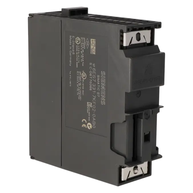
The module requires a 24 V DC load voltage (L+) and a 20-pin front connector. According to Siemens, the module draws a maximum of 30 mA from L+ and up to 50 mA from the backplane bus. For control cabinet planning, it is also important to note the dimensions of 40 mm width, 125 mm height and 117 mm depth. When replacing an existing module, it is therefore advisable to verify not only the part number but also the front connector, power supply and field wiring on a one-to-one basis.
Can I replace an older 6ES7331-7KF00-0AB0 or 6ES7331-7KF01-0AB0 with a 6ES7331-7KF02-0AB0?
Yes. Siemens explicitly documents that the 6ES7331-7KF02-0AB0 is the compatible successor to both the 6ES7331-7KF01-0AB0 and 6ES7331-7KF00-0AB0, and that no modification to the hardware configuration is required. This is particularly valuable for maintenance teams because failures of older variants can often be resolved without extensive software changes. Nevertheless, before installation, the wiring, measurement type and range modules should be checked to ensure that the physical configuration matches the existing sensor setup.
Which procurement and service options are currently available from EICHLER?
According to the current EICHLER product page, several options are available. Repair is listed with a turnaround time of 2–5 days and a price range of €475.07 to €855.12. Exchange service is quoted at €765.81 with an availability of 1–3 days. A used module is listed at €850.91 with 1–3 days availability, while a new module is offered at €945.45, also with 1–3 days availability. In addition, a test report for analogue inputs/outputs can be selected for €159.00 per unit. For procurement-related decisions, this provides a useful basis for comparing repair, exchange and stocking strategies.
When is repair more economical than exchange or purchasing a new unit?
Repair is generally the most economical option when the installation is already optimised for this specific module, the existing wiring should remain unchanged and no functional modifications are required. During the later stages of a product lifecycle, this can be particularly advantageous because the engineering effort, commissioning time and validation risk are often significantly lower than those associated with migration to another platform. An exchange unit is preferable when system availability is the primary concern and the installation must be returned to operation as quickly as possible. New or used modules are particularly suitable for spare-parts stock, critical inventory reserves or parallel spare-parts strategies.