SIEMENS 6ES7315-2EH14-0AB0
-
SIEMENS | PLC Controls | Central Processing Units
- EICHLER-art.no.: K0231650
- EAN: 4025515077770
- UPC: 040892550313
Product description
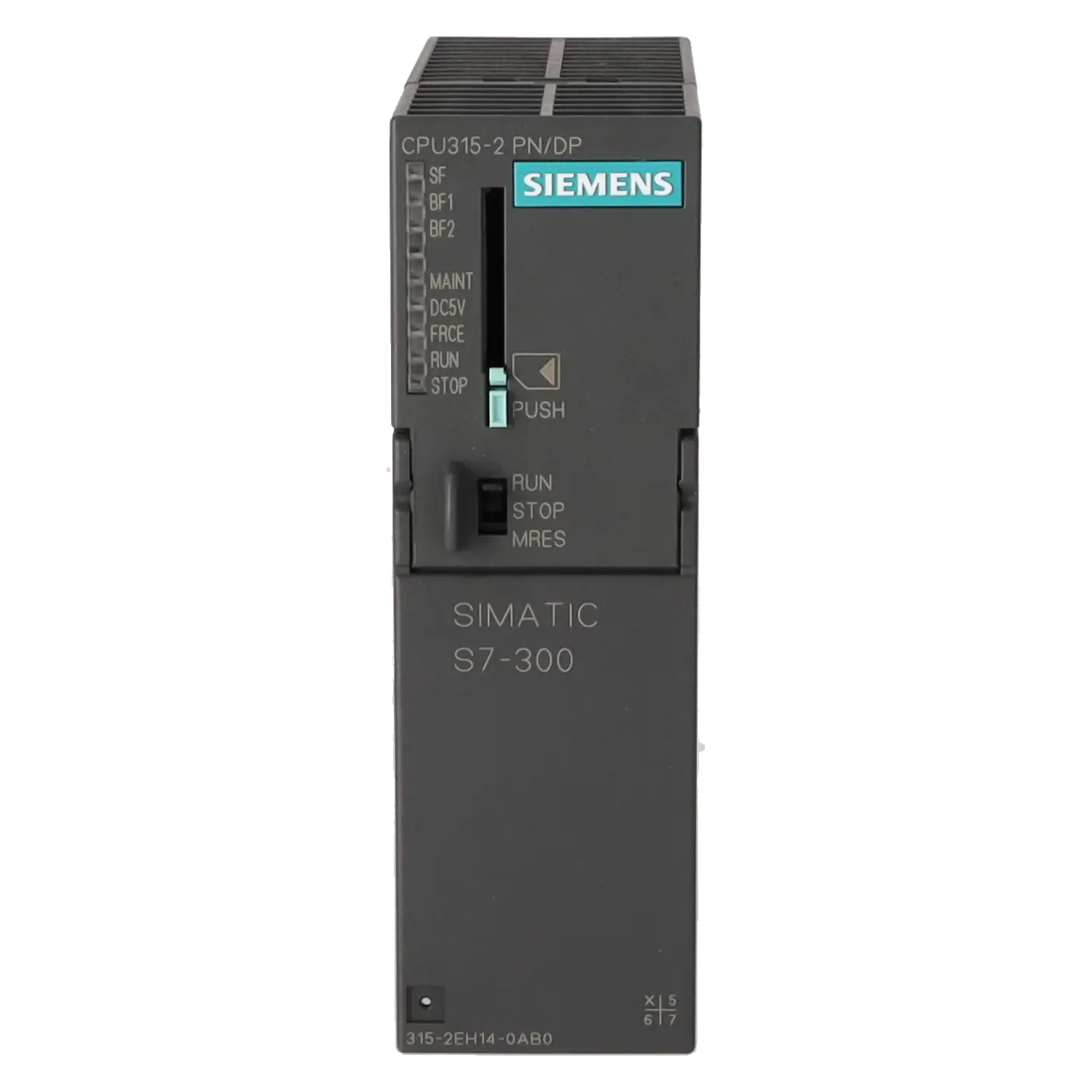
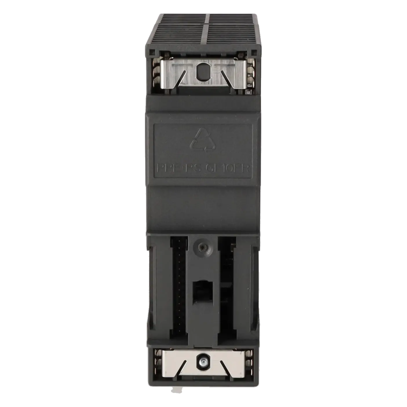
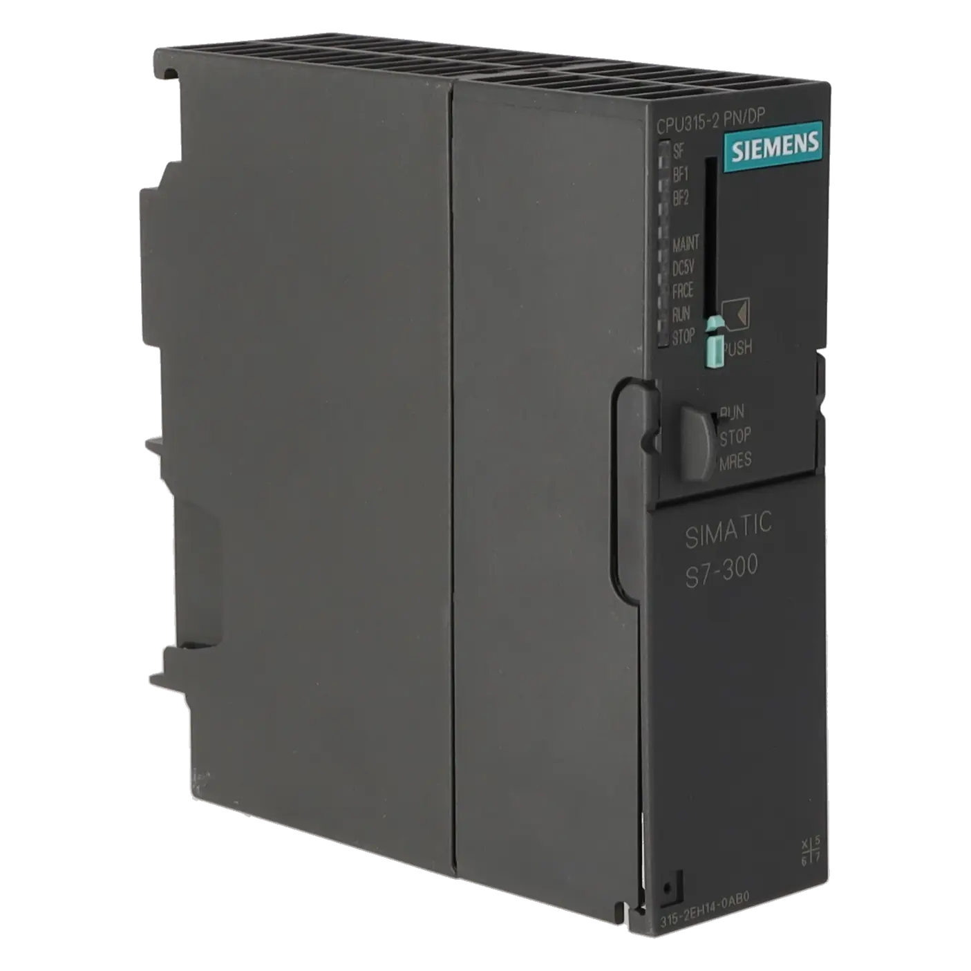
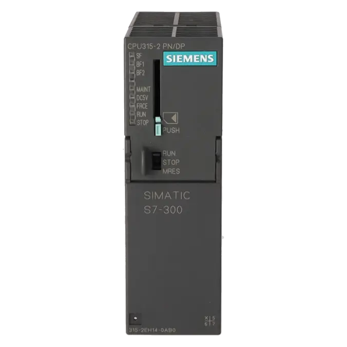
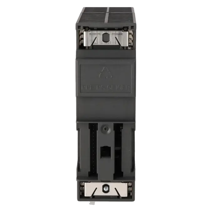
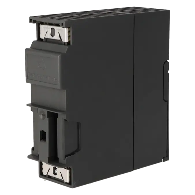
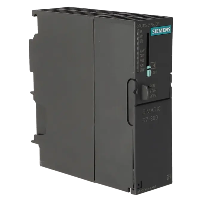
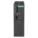
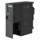
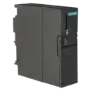
SIMATIC S7-300 CPU 315-2 PN/DP, CENTRAL PROCESSING UNIT WITH 384 KB WORK MEMORY, 1ST INTERFACE MPI/DP 12 MBIT/S, 2ND INTERFACE ETHERNET PROFINET, WITH 2-PORT SWITCH, MICRO MEMORY CARD REQUIRED
Services for SIEMENS 6ES7315-2EH14-0AB0
Repair
from 1.089,63 €
to 1.961,33 €
Replacement
3.215,61 €
2.411,71 €
Used
3.572,91 €
2.679,68 €
New
3.969,90 €
2.977,42 €
SIEMENS |
6ES7315-2EH14-0AB0 –
additional product information
| Delivery information | |||
|---|---|---|---|
| Export identifier | AL: N ECCN: EAR99H | ||
| Net weight | 0.379 | ||
| Quantity | 1 Stück | ||
| Packaging quantity | 1 | ||
| Additional product information | |||
|---|---|---|---|
| Product status | EOP: 2025-10-01 | ||
| EAN | 4025515077770 | ||
| UPC | 040892550313 | ||
| Static lot number | 85371091 | ||
| List indicator | ST73 | ||
| Product group | 4256 | ||
| Country of origin | DE | ||
| Compliance with the substance restrictions according to RoHS directive | Since: 20091125 | ||
| Product classifications | Version | Classification | |
|---|---|---|---|
| eClass | 4 | 27-24-03-02 | |
| eClass | 5.1 | 27-24-22-07 | |
| eClass | 6.0 | 27-24-22-07 | |
| ETIM | 3 | / | |
| ETIM | 4 | EC000236 | |
| ETIM | 5 | EC000236 | |
What is the 6ES7315-2EH14-0AB0 and where is it used?
The 6ES7315-2EH14-0AB0 is a Siemens SIMATIC S7-300 CPU 315-2 PN/DP. It is a central processing unit designed for automation applications where traditional S7-300 architectures, PROFIBUS/MPI and PROFINET connectivity are combined within a single controller. The CPU provides a combined MPI/PROFIBUS DP interface supporting data rates of up to 12 Mbit/s, together with a PROFINET interface featuring an integrated 2-port switch. This makes it particularly suitable for machines and existing installations where decentralised I/O, HMIs, drives and service connections must be integrated reliably. Operation requires a SIMATIC Micro Memory Card (MMC).
Overview of the key technical data and what it means
From a performance perspective, the CPU is positioned in the mid-range of the S7-300 family. It operates from a 24 V DC supply, provides 384 KB of work memory, and uses an MMC of up to 8 MB as removable load memory. In practice, this provides sufficient resources for typical machine and production-line applications, battery-free retentive data storage and a solid foundation for diagnostics and communication tasks. On the communications side, the CPU supports up to 124 PROFIBUS DP nodes and up to 128 PROFINET IO devices. Additional features include an integrated web server, a diagnostic buffer with up to 500 entries, and extensive built-in diagnostic functions. The permitted operating temperature range is 0 to 60 °C.
Product status, life-cycle status and obsolescence
For procurement, maintenance and production management teams, the lifecycle status is particularly important. Siemens officially classifies the 6ES7315-2EH14-0AB0 as a spare part, and the Siemens Industry Mall identifies its lifecycle status as PM410: Product Cancellation, effective from 01 October 2025. The EICHLER product page likewise lists the status as EOP: 2025-10-01. This is a clear indication that active obsolescence management is required: spare-parts inventories should be reviewed, critical replacement components secured, project-specific configurations archived, and repair or replacement strategies defined. In the Siemens product sources reviewed, no officially designated successor was identified for this exact order number. As a result, any migration or replacement strategy should always be assessed on a system-specific basis.
Available EICHLER services and their practical relevance
For operators of older S7-300 installations, the services offered by EICHLER are particularly relevant when downtime must be minimised and existing projects should continue operating without the risks associated with major system modifications. According to the product page, repair, exchange, used equipment and new equipment options are available. Repair is listed with a turnaround time of 2–5 days and includes technical cleaning, preventive maintenance, comprehensive functional testing and a minimum 24-month warranty. An optional test report is also available. Organisations that need to minimise downtime as much as possible may benefit more from an exchange service, whereas those balancing budget constraints and long-term availability may choose used or new equipment. These services are intended exclusively for business customers.
| Attribute | Value |
|---|---|
| General information | |
| Product type designation | CPU 315-2 PN/DP |
| HW functional status | 1 |
| Firmware version | V3.2 |
| Product function | |
| ● Isochronous mode | Yes; Via PROFIBUS DP or PROFINET interface |
| Engineering with | |
| ● Programming package | STEP 7 V5.5 or higher |
| Supply voltage | |
| Rated value (DC) | 24 V |
| permissible range, lower limit (DC) | 20.4 V |
| permissible range, upper limit (DC) | 28.8 V |
| external protection for power supply lines (recommendation) | 2 A min. |
| Mains buffering | |
| ● Mains/voltage failure stored energy time | 5 ms |
| ● Repeat rate, min. | 1 s |
| Input current | |
| Current consumption (rated value) | 750 mA |
| Current consumption (in no-load operation), typ. | 150 mA |
| Inrush current, typ. | 4 A |
| I²t | 1 A²·s |
| Power loss | |
| Power loss, typ. | 4.65 W |
| Memory | |
| Work memory | |
| ● integrated | 384 kbyte |
| ● expandable | No |
| Load memory | |
| ● Plug-in (MMC) | Yes |
| ● Plug-in (MMC), max. | 8 Mbyte |
| ● Data management on MMC (after last programming), min. | 10 a |
| Backup | |
| ● present | Yes; Guaranteed by MMC (maintenance-free) |
| ● without battery | Yes; Program and data |
| CPU processing times | |
| for bit operations, typ. | 0.05 µs |
| for word operations, typ. | 0.09 µs |
| for fixed point arithmetic, typ. | 0.12 µs |
| for floating point arithmetic, typ. | 0.45 µs |
| CPU-blocks | |
| Number of blocks (total) | 1 024; (DBs, FCs, FBs); the maximum number of loadable blocks can be reduced by the MMC used. |
| DB | |
| ● Number, max. | 1 024; Number range: 1 to 16000 |
| ● Size, max. | 64 kbyte |
| FB | |
| ● Number, max. | 1 024; Number range: 0 to 7999 |
| ● Size, max. | 64 kbyte |
| FC | |
| ● Number, max. | 1 024; Number range: 0 to 7999 |
| ● Size, max. | 64 kbyte |
| OB | |
| ● Size, max. | 64 kbyte |
| ● Number of free cycle OBs | 1; OB 1 |
| ● Number of time alarm OBs | 1; OB 10 |
| ● Number of delay alarm OBs | 2; OB 20, 21 |
| ● Number of cyclic interrupt OBs | 4; OB 32, 33, 34, 35 |
| ● Number of process alarm OBs | 1; OB 40 |
| ● Number of DPV1 alarm OBs | 3; OB 55, 56, 57 |
| ● Number of isochronous mode OBs | 1; OB 61 |
| ● Number of startup OBs | 1; OB 100 |
| ● Number of asynchronous error OBs | 6; OB 80, 82, 83, 85, 86, 87 (OB83 only for PROFINET IO) |
| ● Number of synchronous error OBs | 2; OB 121, 122 |
| Nesting depth | |
| ● per priority class | 16 |
| ● additional within an error OB | 4 |
| Counters, timers and their retentivity | |
| S7 counter | |
| ● Number | 256 |
| Retentivity | |
| — adjustable | Yes |
| — preset | Z 0 to Z 7 |
| Counting range | |
| — adjustable | Yes |
| — lower limit | 0 |
| — upper limit | 999 |
| IEC counter | |
| ● present | Yes |
| ● Type | SFB |
| ● Number | Unlimited (limited only by RAM capacity) |
| S7 times | |
| ● Number | 256 |
| Retentivity | |
| — adjustable | Yes |
| — preset | No retentivity |
| Time range | |
| — lower limit | 10 ms |
| — upper limit | 9 990 s |
| IEC timer | |
| ● present | Yes |
| ● Type | SFB |
| ● Number | Unlimited (limited only by RAM capacity) |
| Data areas and their retentivity | |
| Retentive data area (incl. timers, counters, flags), max. | 128 kbyte |
| Flag | |
| ● Size, max. | 2 048 byte |
| ● Retentivity available | Yes; MB 0 to MB 2 047 |
| ● Retentivity preset | MB 0 to MB 15 |
| ● Number of clock memories | 8; 1 memory byte |
| Data blocks | |
| ● Retentivity adjustable | Yes; via non-retain property on DB |
| ● Retentivity preset | Yes |
| Local data | |
| ● per priority class, max. | 32 768 byte; Max. 2048 bytes per block |
| Address area | |
| I/O address area | |
| ● Inputs | 2 048 byte |
| ● Outputs | 2 048 byte |
| of which distributed | |
| — Inputs | 2 048 byte |
| — Outputs | 2 048 byte |
| Process image | |
| ● Inputs | 2 048 byte |
| ● Outputs | 2 048 byte |
| ● Inputs, adjustable | 2 048 byte |
| ● Outputs, adjustable | 2 048 byte |
| ● Inputs, default | 128 byte |
| ● Outputs, default | 128 byte |
| Subprocess images | |
| ● Number of subprocess images, max. | 1; With PROFINET IO, the length of the user data is limited to 1600 bytes |
| Digital channels | |
| ● Inputs | 16 384 |
| — of which central | 1 024 |
| ● Outputs | 16 384 |
| — of which central | 1 024 |
| Analog channels | |
| ● Inputs | 1 024 |
| — of which central | 256 |
| ● Outputs | 1 024 |
| — of which central | 256 |
| Hardware configuration | |
| Number of expansion units, max. | 3 |
| Number of DP masters | |
| ● integrated | 1 |
| ● via CP | 4 |
| Number of operable FMs and CPs (recommended) | |
| ● FM | 8 |
| ● CP, PtP | 8 |
| ● CP, LAN | 10 |
| Rack | |
| ● Racks, max. | 4 |
| ● Modules per rack, max. | 8 |
| Time of day | |
| Clock | |
| ● Hardware clock (real-time) | Yes |
| ● retentive and synchronizable | Yes |
| ● Backup time | 6 wk; At 40 °C ambient temperature |
| ● Deviation per day, max. | 10 s; Typ.: 2 s |
| ● Behavior of the clock following POWER-ON | Clock continues running after POWER OFF |
| ● Behavior of the clock following expiry of backup period | the clock continues at the time of day it had when power was switched off |
| Operating hours counter | |
| ● Number | 1 |
| ● Number/Number range | 0 |
| ● Range of values | 0 to 2^31 hours (when using SFC 101) |
| ● Granularity | 1 h |
| ● retentive | Yes; Must be restarted at each restart |
| Clock synchronization | |
| ● supported | Yes |
| ● to MPI, master | Yes |
| ● on MPI, device | Yes |
| ● to DP, master | Yes; With DP slave only slave clock |
| ● on DP, device | Yes |
| ● in AS, master | Yes |
| ● in AS, device | Yes |
| ● on Ethernet via NTP | Yes; As client |
| Digital inputs | |
| Number of digital inputs | 0 |
| Digital outputs | |
| Number of digital outputs | 0 |
| Analog inputs | |
| Number of analog inputs | 0 |
| Interfaces | |
| Number of PROFINET interfaces | 1; 2 ports (switch) RJ45 |
| Number of RS 485 interfaces | 1; Combined MPI / PROFIBUS DP |
| Number of RS 422 interfaces | 0 |
| 1. Interface | |
| Interface type | Integrated RS 485 interface |
| Isolated | Yes |
| Interface types | |
| ● RS 485 | Yes |
| ● Output current of the interface, max. | 200 mA |
| Protocols | |
| ● MPI | Yes |
| ● PROFIBUS DP master | Yes |
| ● PROFIBUS DP device | Yes |
| ● Point-to-point connection | No |
| MPI | |
| ● Transmission rate, max. | 12 Mbit/s |
| Services | |
| — PG/OP communication | Yes |
| — Routing | Yes |
| — Global data communication | Yes |
| — S7 basic communication | Yes |
| — S7 communication | Yes |
| — S7 communication, as client | No; but via CP and loadable FB |
| — S7 communication, as server | Yes |
| PROFIBUS DP master | |
| ● Transmission rate, max. | 12 Mbit/s |
| ● max. number of DP devices | 124 |
| Services | |
| — PG/OP communication | Yes |
| — Routing | Yes |
| — Global data communication | No |
| — S7 basic communication | Yes; I blocks only |
| — S7 communication | Yes |
| — S7 communication, as client | No |
| — S7 communication, as server | Yes |
| — Equidistance | Yes |
| — Isochronous mode | Yes; OB 61; isochronous mode can only be used alternatively on PROFIBUS DP or PROFINET IO |
| — SYNC/FREEZE | Yes |
| — activation/deactivation of DP devices | Yes |
| — max. number of DP devices that can be activated/deactivated at the same time | 8 |
| — Direct data exchange (slave-to-slave communication) | Yes; as subscriber |
| — DPV1 | Yes |
| Address area | |
| — Inputs, max. | 2 kbyte |
| — Outputs, max. | 2 kbyte |
| User data per DP device | |
| — Inputs, max. | 244 byte |
| — Outputs, max. | 244 byte |
| PROFIBUS DP device | |
| ● Transmission rate, max. | 12 Mbit/s |
| ● automatic baud rate search | Yes; only with passive interface |
| ● Address area, max. | 32 |
| ● User data per address area, max. | 32 byte |
| Services | |
| — PG/OP communication | Yes |
| — Routing | Yes; Only with active interface |
| — Global data communication | No |
| — S7 basic communication | No |
| — S7 communication | Yes |
| — S7 communication, as client | No |
| — S7 communication, as server | Yes; Connection configured on one side only |
| — Direct data exchange (slave-to-slave communication) | Yes |
| — DPV1 | No |
| Transfer memory | |
| — Inputs | 244 byte |
| — Outputs | 244 byte |
| 2. Interface | |
| Interface type | PROFINET |
| Isolated | Yes |
| automatic detection of transmission rate | Yes; 10/100 Mbit/s |
| Autonegotiation | Yes |
| Autocrossing | Yes |
| Change of IP address at runtime, supported | Yes |
| Interface types | |
| ● RJ 45 (Ethernet) | Yes |
| ● Number of ports | 2 |
| ● integrated switch | Yes |
| Protocols | |
| ● MPI | No |
| ● PROFINET IO Controller | Yes; Also simultaneously with IO-Device functionality |
| ● PROFINET IO Device | Yes; Also simultaneously with IO Controller functionality |
| ● PROFINET CBA | Yes |
| ● PROFIBUS DP master | No |
| ● PROFIBUS DP device | No |
| ● Open IE communication | Yes; Via TCP/IP, ISO on TCP, and UDP |
| ● Web server | Yes |
| ● Media redundancy | Yes |
| PROFINET IO Controller | |
| ● Transmission rate, max. | 100 Mbit/s |
| Services | |
| — PG/OP communication | Yes |
| — Routing | Yes |
| — S7 communication | Yes; With loadable FBs, max. configurable connections: 14, max. number of instances: 32 |
| — Isochronous mode | Yes; OB 61; isochronous mode can only be used alternatively on PROFIBUS DP or PROFINET IO |
| — IRT | Yes |
| — Shared device | Yes |
| — Prioritized startup | Yes |
| — Number of IO devices with prioritized startup, max. | 32 |
| — Number of connectable IO Devices, max. | 128 |
| — Of which IO devices with IRT, max. | 64 |
| — of which in line, max. | 64 |
| — Number of IO Devices with IRT and the option "high flexibility" | 128 |
| — of which in line, max. | 61 |
| — Number of connectable IO Devices for RT, max. | 128 |
| — of which in line, max. | 128 |
| — Activation/deactivation of IO Devices | Yes |
| — Number of IO Devices that can be simultaneously activated/deactivated, max. | 8 |
| — IO Devices changing during operation (partner ports), supported | Yes |
| — Number of IO Devices per tool, max. | 8 |
| — Device replacement without swap medium | Yes |
| — Send cycles | 250 μs, 500 μs,1 ms; 2 ms, 4 ms (not in the case of IRT with "high flexibility" option) |
| — Updating time | 250 µs to 512 ms (depending on the operating mode, see Manual "S7-300 CPU 31xC and CPU 31x, technical Data" for more details) |
| Address area | |
| — Inputs, max. | 2 kbyte |
| — Outputs, max. | 2 kbyte |
| — User data consistency, max. | 1 024 byte |
| PROFINET IO Device | |
| Services | |
| — PG/OP communication | Yes |
| — Routing | Yes |
| — S7 communication | Yes; With loadable FBs, max. configurable connections: 14, max. number of instances: 32 |
| — Isochronous mode | No |
| — IRT | Yes |
| — PROFIenergy | Yes; With SFB 73 / 74 prepared for loadable PROFIenergy standard FB for I-Device |
| — Shared device | Yes |
| — Number of IO Controllers with shared device, max. | 2 |
| Transfer memory | |
| — Inputs, max. | 1 440 byte; Per IO Controller with shared device |
| — Outputs, max. | 1 440 byte; Per IO Controller with shared device |
| Submodules | |
| — Number, max. | 64 |
| — User data per submodule, max. | 1 024 byte |
| PROFINET CBA | |
| ● acyclic transmission | Yes |
| ● cyclic transmission | Yes |
| Open IE communication | |
| ● Number of connections, max. | 8 |
| ● Local port numbers used at the system end | 0, 20, 21, 23, 25, 80, 102, 135, 161, 443, 8080, 34962, 34963, 34964, 65532, 65533, 65534, 65535 |
| ● Keep-alive function, supported | Yes |
| Protocols | |
| PROFIsafe | No |
| Redundancy mode | |
| Media redundancy | |
| — Switchover time on line break, typ. | 200 ms; PROFINET MRP |
| — Number of stations in the ring, max. | 50 |
| Open IE communication | |
| ● TCP/IP | Yes; via integrated PROFINET interface and loadable FBs |
| — Number of connections, max. | 8 |
| — Data length for connection type 01H, max. | 1 460 byte |
| — Data length for connection type 11H, max. | 32 768 byte |
| — several passive connections per port, supported | Yes |
| ● ISO-on-TCP (RFC1006) | Yes; via integrated PROFINET interface and loadable FBs |
| — Number of connections, max. | 8 |
| — Data length, max. | 32 768 byte |
| ● UDP | Yes; via integrated PROFINET interface and loadable FBs |
| — Number of connections, max. | 8 |
| — Data length, max. | 1 472 byte |
| Web server | |
| ● supported | Yes |
| ● User-defined websites | Yes |
| ● Number of HTTP clients | 5 |
| Communication functions | |
| PG/OP communication | Yes |
| Data record routing | Yes |
| Global data communication | |
| ● supported | Yes |
| ● Number of GD loops, max. | 8 |
| ● Number of GD packets, max. | 8 |
| ● Number of GD packets, transmitter, max. | 8 |
| ● Number of GD packets, receiver, max. | 8 |
| ● Size of GD packets, max. | 22 byte |
| ● Size of GD packet (of which consistent), max. | 22 byte |
| S7 basic communication | |
| ● supported | Yes |
| ● User data per job, max. | 76 byte |
| ● User data per job (of which consistent), max. | 76 byte; 76 bytes (with X_SEND or X_RCV); 64 bytes (with X_PUT or X_GET as server) |
| S7 communication | |
| ● supported | Yes |
| ● as server | Yes |
| ● as client | Yes; via integrated PROFINET interface and loadable FB or via CP and loadable FB |
| ● User data per job, max. | See online help of STEP 7 (shared parameters of the SFBs/FBs and of the SFCs/FCs of S7 Communication) |
| S5 compatible communication | |
| ● supported | Yes; via CP and loadable FC |
| PROFINET CBA (at set setpoint communication load) | |
| ● Setpoint for the CPU communication load | 50 % |
| ● Number of remote interconnection partners | 32 |
| ● number of master/device functions | 30 |
| ● total of all master/device connections | 1 000 |
| ● data length of all incoming master/device connections, max. | 4 000 byte |
| ● data length of all outgoing master/device connections, max. | 4 000 byte |
| ● Number of device-internal and PROFIBUS interconnections | 500 |
| ● Data length of device-internal und PROFIBUS interconnections, max. | 4 000 byte |
| ● Data length per connection, max. | 1 400 byte |
| Remote interconnections with cyclic transmission | |
| — Transmission frequency: Transmission interval, min. | 10 ms |
| — Number of incoming interconnections | 200 |
| — Number of outgoing interconnections | 200 |
| — Data length of all incoming interconnections, max. | 2 000 byte |
| — Data length of all outgoing interconnections, max. | 2 000 byte |
| — Data length per connection, max. | 450 byte |
| HMI variables via PROFINET (acyclic) | |
| — Number of stations that can log on for HMI variables (PN OPC/iMap) | 3; 2x PN OPC/1x iMap |
| — HMI variable updating | 500 ms |
| — Number of HMI variables | 200 |
| — Data length of all HMI variables, max. | 2 000 byte |
| PROFIBUS proxy functionality | |
| — supported | Yes |
| — Number of linked PROFIBUS devices | 16 |
| — Data length per connection, max. | 240 byte; Slave-dependent |
| Number of connections | |
| ● overall | 16 |
| ● usable for PG communication | 15 |
| — reserved for PG communication | 1 |
| — adjustable for PG communication, min. | 1 |
| — adjustable for PG communication, max. | 15 |
| ● usable for OP communication | 15 |
| — reserved for OP communication | 1 |
| — adjustable for OP communication, min. | 1 |
| — adjustable for OP communication, max. | 15 |
| ● usable for S7 basic communication | 14 |
| — reserved for S7 basic communication | 0 |
| — adjustable for S7 basic communication, min. | 0 |
| — adjustable for S7 basic communication, max. | 14 |
| ● usable for S7 communication | 14 |
| — reserved for S7 communication | 0 |
| — adjustable for S7 communication, min. | 0 |
| — adjustable for S7 communication, max. | 14 |
| ● total number of instances, max. | 32 |
| ● usable for routing | X1 as MPI: max. 10; X1 as DP master: max. 24; X1 as DP slave (active): max. 14; X2 as PROFINET: 24 max. |
| S7 message functions | |
| Number of login stations for message functions, max. | 16; Depending on the configured connections for PG/OP and S7 basic communication |
| Process diagnostic messages | Yes |
| simultaneously active Alarm_S blocks, max. | 300 |
| Test commissioning functions | |
| Status block | Yes; Up to 2 simultaneously |
| Single step | Yes |
| Number of breakpoints | 4 |
| Status/control | |
| ● Status/control variable | Yes |
| ● Variables | Inputs, outputs, memory bits, DB, times, counters |
| ● Number of variables, max. | 30 |
| — of which status variables, max. | 30 |
| — of which control variables, max. | 14 |
| Forcing | |
| ● Forcing | Yes |
| ● Forcing, variables | Inputs, outputs |
| ● Number of variables, max. | 10 |
| Diagnostic buffer | |
| ● present | Yes |
| ● Number of entries, max. | 500 |
| — adjustable | No |
| — of which powerfail-proof | 100; Only the last 100 entries are retained |
| ● Number of entries readable in RUN, max. | 499 |
| — adjustable | Yes; From 10 to 499 |
| — preset | 10 |
| Service data | |
| ● can be read out | Yes |
| Ambient conditions | |
| Ambient temperature during operation | |
| ● min. | 0 °C |
| ● max. | 60 °C |
| Configuration | |
| Configuration software | |
| ● STEP 7 | Yes; V5.5 or higher |
| Programming | |
| ● Command set | see instruction list |
| ● Nesting levels | 8 |
| ● System functions (SFC) | see instruction list |
| ● System function blocks (SFB) | see instruction list |
| Programming language | |
| — LAD | Yes |
| — FBD | Yes |
| — STL | Yes |
| — SCL | Yes |
| — CFC | Yes |
| — GRAPH | Yes |
| — HiGraph® | Yes |
| Know-how protection | |
| ● User program protection/password protection | Yes |
| ● Block encryption | Yes; With S7 block Privacy |
| Dimensions | |
| Width | 40 mm |
| Height | 125 mm |
| Depth | 130 mm |
| Weights | |
| Weight, approx. | 340 g |
| Fault description | Possible solution |
|---|---|
| Why is the BF LED on my CPU 315-2 PN/DP flashing continuously on PROFINET? | A flashing BF LED indicates that, as a PROFINET IO Controller, the CPU cannot establish communication with all assigned IO devices. Common causes include failed or unreachable IO devices, incorrect project configuration, mismatched device names, duplicate or incorrect IP addresses, or a broken Ethernet connection. Check the network cables, switch connections, power supply to the devices, device names and IP addressing. Afterwards, read the diagnostic buffer in STEP 7. If OB86 has not been loaded, such a fault can cause the CPU to transition from RUN to STOP in addition to generating the communication error. |
| Why does the CPU enter STOP after a station or peripheral fault? | When a PROFINET or PROFIBUS device fails, the CPU handles the event using diagnostic organisation blocks (OBs). OB86 is relevant for station failures, while OB122 is used for peripheral access errors. Siemens explains that OB122 is called whenever an error occurs while accessing module data. If OB122 is not present in the user program, the CPU changes from RUN to STOP. The same principle applies in many PROFINET fault scenarios involving OB86. Following any fault, it is therefore important to determine which OB was triggered, review the contents of the diagnostic buffer, and verify that the actual hardware configuration matches the intended system configuration. |
| Why does the CPU display SF or enter STOP after inserting the MMC? | The CPU requires a SIMATIC Micro Memory Card (MMC) for operation. Siemens notes that data on the MMC can become corrupted if the card is removed during a write operation and that it must not be removed while the CPU is in RUN mode. In practical situations, an MMC containing an incorrect or outdated hardware configuration can also trigger SF alarms, because the CPU attempts to load the project stored on the card during start-up. In most cases, the solution is to place the CPU in STOP or remove the power supply, insert the correct MMC, reset or clear the card if necessary, and then download the correct hardware configuration to the CPU again. |
| Why is only the SF LED flashing at 2 Hz while no other LEDs are active? | According to Siemens, this LED pattern is typically associated with an interrupted firmware update, for example due to a power interruption or removal of the Micro Memory Card during the update process. In this condition, the valid firmware may have been lost, although the boot block remains intact. Siemens recommends repeating the firmware update using a valid update file and following the documented procedure exactly. It is important not to interrupt the update process and to ensure that the CPU is accessible online or that a suitable MMC containing the update files is installed. |
| Why does STEP 7 report that the configured module does not match the installed hardware? | This message usually appears when the configured order number, firmware version or hardware catalogue entry does not correspond to the actual device installed. Siemens specifies STEP 7 V5.5 or later as the engineering platform for the 6ES7315-2EH14-0AB0. Experience from typical PLC forum cases shows that an incorrect or incomplete hardware configuration can lead to SF alarms and online discrepancies. Therefore, verify the exact MLFB number, the CPU firmware version, the installed STEP 7 version, and confirm that the correct CPU type has been selected within the hardware catalogue. |
Is the 6ES7315-2EH14-0AB0 still active in the Siemens lifecycle?
No. Siemens no longer classifies the module as an active standard product and instead lists it as a spare part with the lifecycle status PM410: Product Cancellation, effective from 01 October 2025. For operators, this means that the CPU remains technically relevant but its long-term availability should no longer be taken for granted. Anyone using this CPU in a production-critical environment should therefore secure spare-parts stock, repair options and comprehensive documentation of the hardware version, software version and parameterisation.
Does the CPU 315-2 PN/DP require a Micro Memory Card?
Yes. Siemens explicitly states that this CPU requires a SIMATIC Micro Memory Card (MMC) for operation. The MMC functions as the load memory and stores the project data permanently. In practice, the card should only be removed when the power supply is switched off or the CPU is in STOP mode, and only when no write operation is active. A damaged or incorrectly prepared MMC can result in start-up problems, SF alarms or an inconsistent project state.
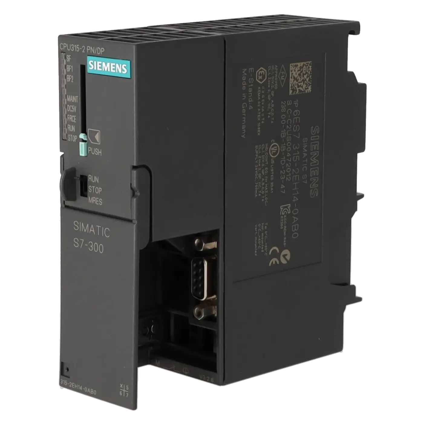
Can I use PROFIBUS and PROFINET simultaneously with the 6ES7315-2EH14-0AB0?
Yes. This is one of the key strengths of the CPU. The module provides an RS-485 interface for MPI/PROFIBUS DP communication as well as a PROFINET interface with two ports and an integrated switch. On the PROFIBUS side, it supports both master and device functions, while on the PROFINET side it supports features including IO Controller, IO Device, web server functionality and open Ethernet communication. This makes the CPU particularly useful in retrofit projects where existing PROFIBUS networks must remain operational while new devices are integrated via PROFINET.
Which software is required for project engineering, diagnostics and service?
Siemens specifies STEP 7 V5.5 or later for project engineering. In addition, the CPU offers integrated diagnostic functions such as a diagnostic buffer, status and control functions, breakpoints and an integrated web server. For maintenance personnel, this is important because faults can be analysed not only via LED indicators but also through structured diagnostic tools and online diagnostics. In older installations with multiple service providers, these capabilities can significantly reduce the time required to identify the root cause of a fault.
How many devices and IO nodes can the CPU support?
The CPU supports up to 124 PROFIBUS DP devices and up to 128 PROFINET IO devices. It also provides a process image capacity of up to 2,048 bytes of inputs and 2,048 bytes of outputs. For procurement and engineering teams, these figures provide a useful indication of whether the CPU remains sufficient for an existing machine or production cell, or whether future expansion may be limited by communication capacity or system size constraints.
When is repair, exchange, used equipment or new equipment the most appropriate option?
Repair is generally the best choice when the existing CPU should remain part of the installation and a rapid return to operation can be achieved with predictable effort. An exchange unit is often preferable during an unplanned production stoppage when a fully functional replacement is required immediately. Used equipment can be attractive when budget considerations and short-term availability are more important than obtaining a factory-new device. New equipment is typically chosen when maximum assurance regarding stock availability and procurement standards is required. According to the referenced EICHLER product page, all four options are available for this CPU, together with an optional test report, providing additional verification and documentation where required.