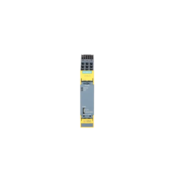
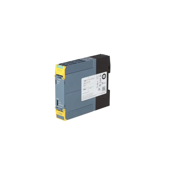
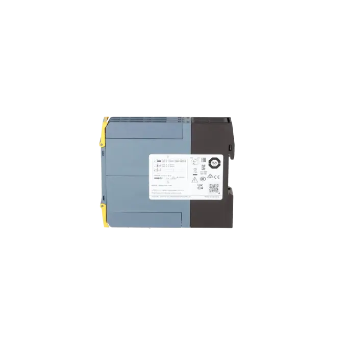
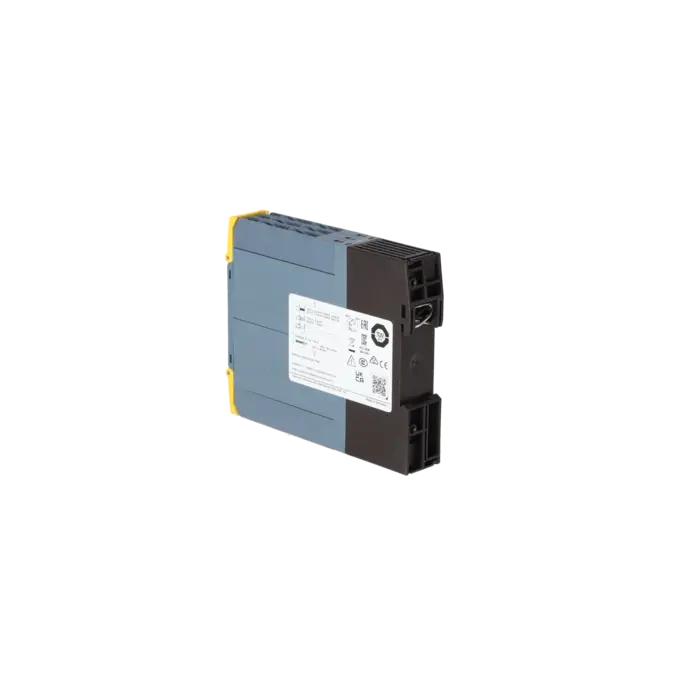
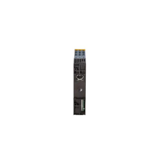
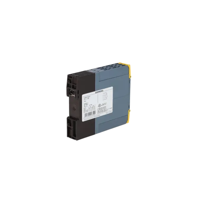
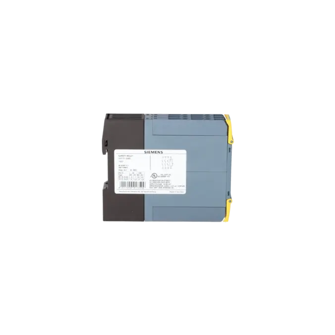
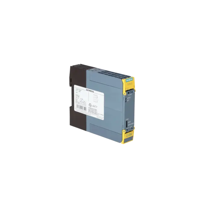
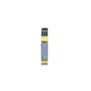
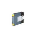
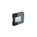
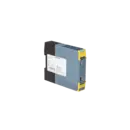
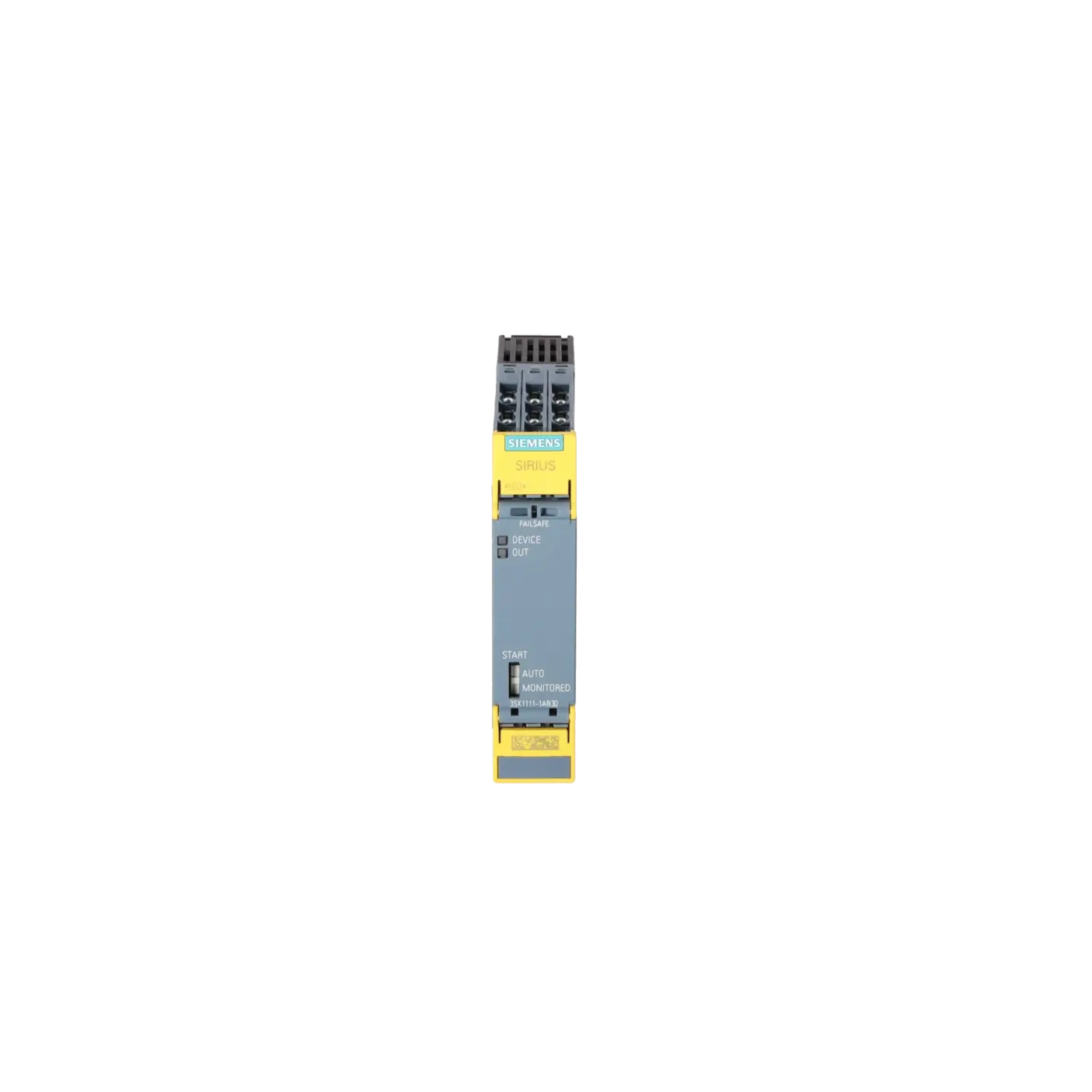
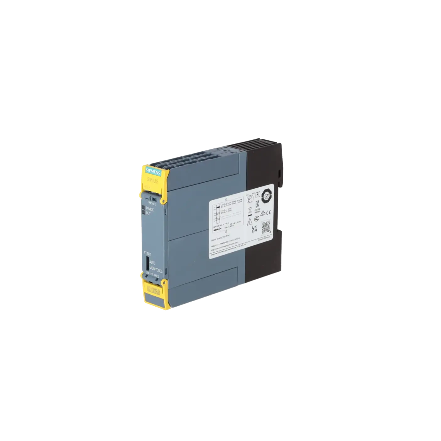
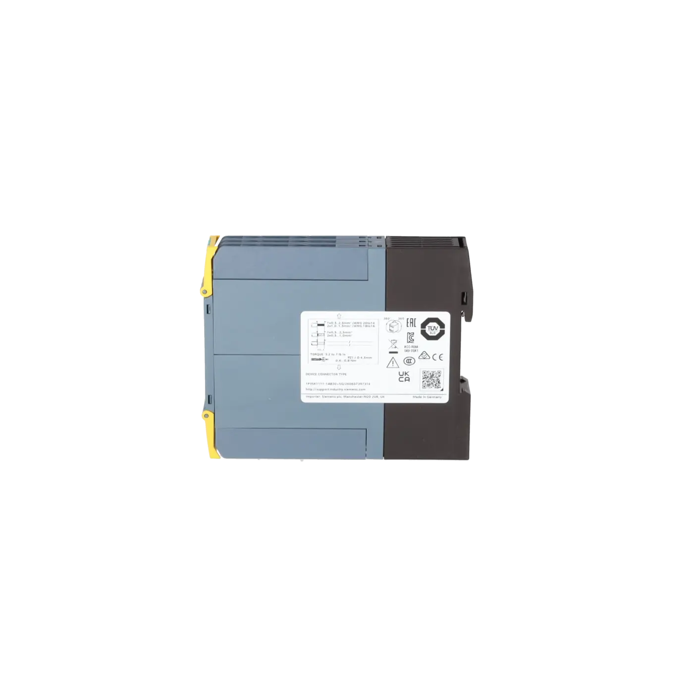
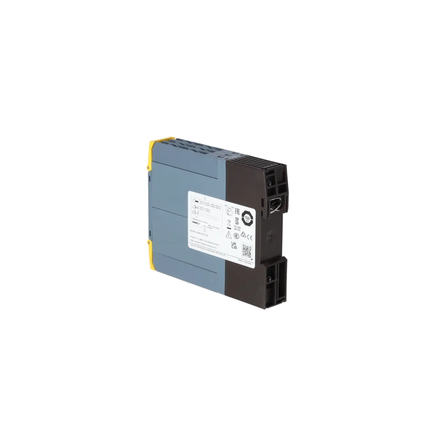
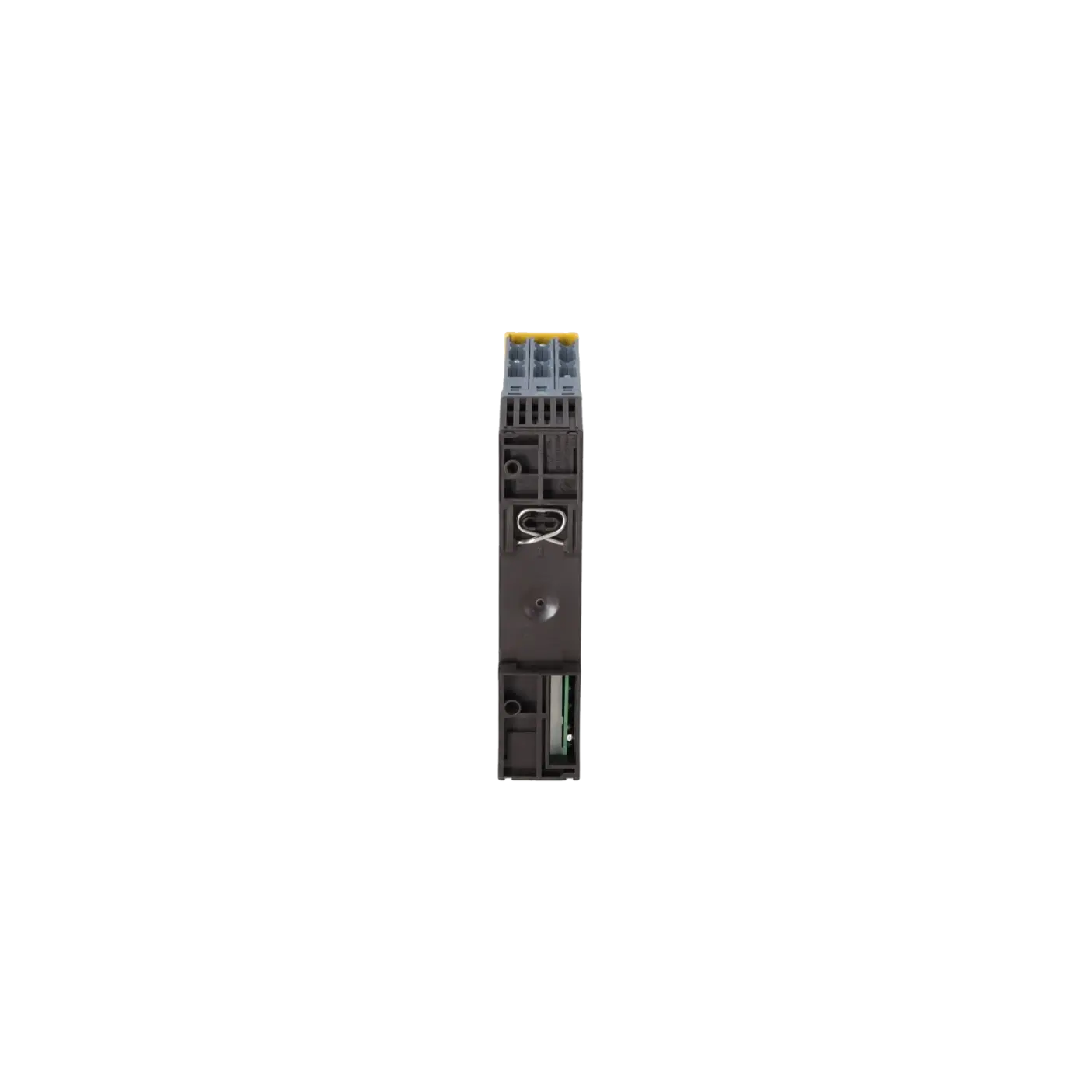
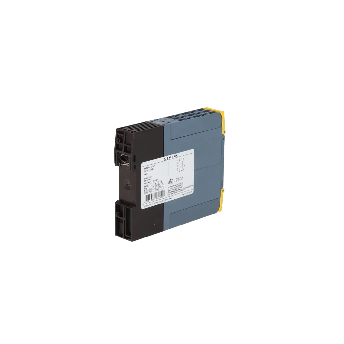
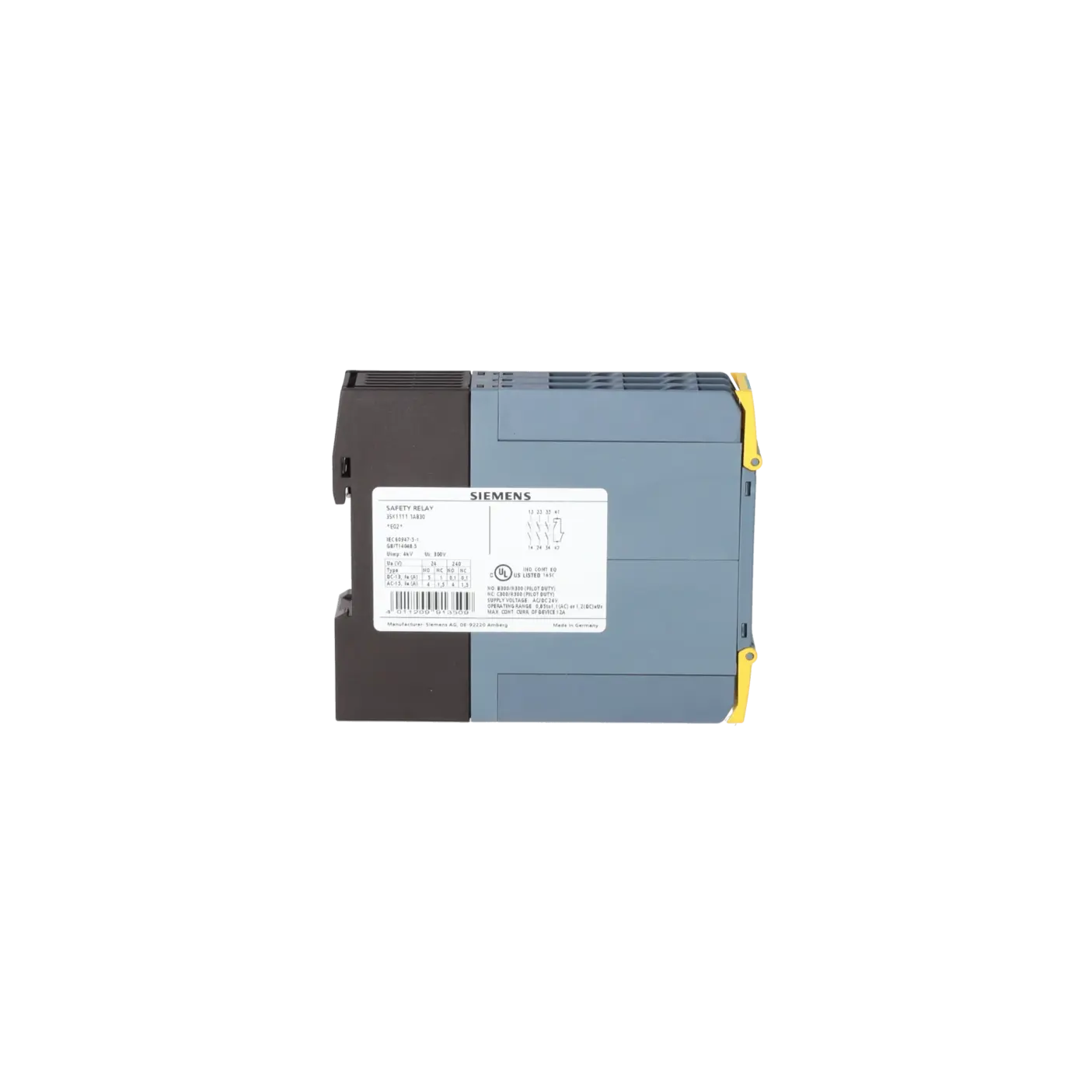
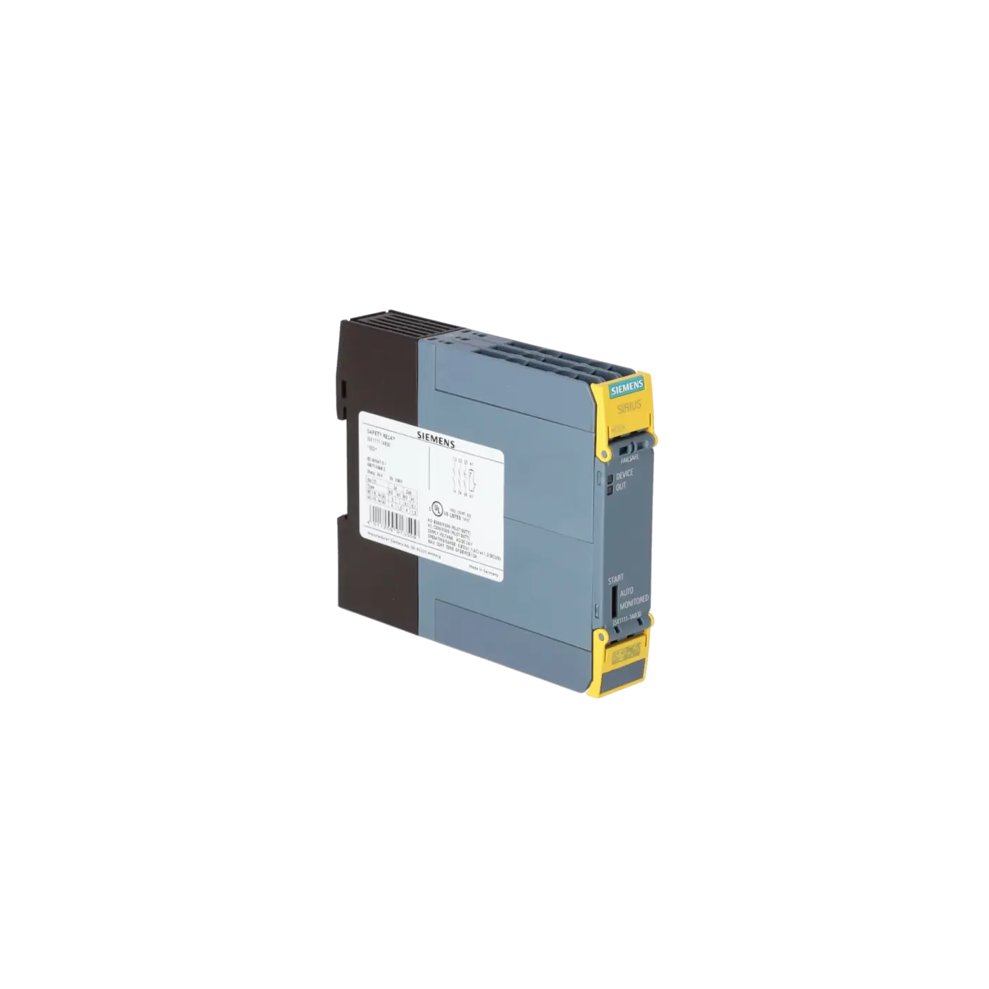
| product brand name |
SIRIUS |
| product category |
Safety relays |
| product designation |
safety relays |
| design of the product |
Relay enabling circuits |
| product type designation |
3SK1 |
| product line |
Standard basic unit |
| Product Function |
|
| product function parameterizable |
sensor floating / sensor non-floating, monitored start-up / automatic start |
| product function |
|
| ● automatic start |
Yes |
| ● light barrier monitoring |
Yes |
| ● protective door monitoring |
Yes |
| ● magnetically operated switch monitoring NC-NO |
No |
| ● magnetically operated switch monitoring NC-NC |
Yes |
| ● laser scanner monitoring |
Yes |
| ● light array monitoring |
Yes |
| ● EMERGENCY OFF function |
Yes |
| ● monitored start-up |
Yes |
| ● pressure-sensitive mat monitoring |
No |
| product feature cross-circuit-proof |
Yes |
| suitability for interaction press control |
No |
| suitability for operation device connector 3ZY12 |
No |
| suitability for use |
|
| ● monitoring of floating sensors |
Yes |
| ● monitoring of non-floating sensors |
Yes |
| ● position switch monitoring |
Yes |
| ● EMERGENCY-OFF circuit monitoring |
Yes |
| ● opto-electronic protection device monitoring |
Yes |
| ● magnetically operated switch monitoring |
Yes |
| ● safety-related circuits |
Yes |
| General technical data |
|
| certificate of suitability UL approval |
Yes |
| product feature protective coating on printed-circuit board |
No |
| power loss [W] maximum |
2 W |
| insulation voltage rated value |
300 V |
| degree of pollution |
3 |
| overvoltage category |
3 |
| surge voltage resistance rated value |
4 000 V |
| protection class IP of the enclosure |
IP20 |
| shock resistance |
10 g / 11 ms |
| vibration resistance according to IEC 60068-2-6 |
5 ... 500 Hz: 0.75 mm |
| operating frequency maximum |
360 1/h |
| reference code according to IEC 81346-2 |
F |
| Substance Prohibitance (day/month/year) |
41040 |
| SVHC substance name |
Lead CAS-No. 7439-92-1 |
|
Lead monoxide (lead oxide) CAS-No. 1317-36-8 |
|
2-methyl-1-(4-methylthiophenyl)-2-morpholinopropan-1-one CAS-No. 71868-10-5 |
|
Melamine CAS-No. 108-78-1 |
|
6,6'-di-tert-butyl-2,2'-methylenedi-p-cresol CAS-No. 119-47-1 |
|
4,4'-isopropylidenediphenol (Bisphenol A, BPA) CAS-No. 80-05-7 |
| Net Weight |
0.226 kg |
| Ambient conditions |
|
| installation altitude at height above sea level maximum |
4 000 m |
| ● note |
Derating, see Product Notification 109792701 |
| ambient temperature |
|
| ● during operation |
-25 ... +60 °C |
| ● during storage |
-40 ... +80 °C |
| relative humidity during operation |
10 ... 95 % |
| air pressure according to SN 31205 |
900 ... 1 060 hPa |
| Electromagnetic compatibility |
|
| installation environment regarding EMC |
This product is suitable for Class B environments and can also be used in domestic environments. |
| EMC emitted interference |
IEC 60947-5-1, Class B |
| Safety related data |
|
| product function suitable for safety function |
Yes |
| safe state |
Safety outputs switched off |
| test wear-related service life necessary |
Yes |
| function test interval maximum |
1 a |
| stop category according to IEC 60204-1 |
0 |
| IEC 62061 |
|
| SIL Claim Limit (subsystem) according to EN 62061 |
3 |
| Safety Integrity Level (SIL) |
|
| ● according to IEC 62061 |
SIL 3 |
| ● at single-channel evaluation according to IEC 62061 |
1 |
| ● at 2-channel evaluation according to IEC 62061 |
3 |
| PFHD with high demand rate according to IEC 62061 |
0.0000000017 |
| ISO 13849 |
|
| category according to EN ISO 13849-1 |
4 |
| performance level (PL) |
|
| ● according to ISO 13849-1 |
PL e |
| ● at single-channel evaluation according to ISO 13849-1 |
c |
| ● at 2-channel evaluation according to ISO 13849-1 |
e |
| category |
|
| ● according to ISO 13849-1 |
4 |
| ● at 2-channel evaluation according to ISO 13849-1 |
4 |
| overdimensioning according to ISO 13849-2 necessary |
No |
| IEC 61508 |
|
| Safety Integrity Level (SIL) |
|
| ● according to IEC 61508 |
3 |
| ● at single-channel evaluation according to IEC 61508 |
1 |
| ● at 2-channel evaluation according to IEC 61508 |
3 |
| safety device type according to IEC 61508-2 |
Type A |
| PFHD with high demand rate according to IEC 61508 |
0.0000000017 |
| PFDavg with low demand rate according to IEC 61508 |
0.000001 |
| Safe failure fraction (SFF) |
99 % |
| hardware fault tolerance |
|
| ● according to IEC 61508 |
1 |
| ● at single-channel evaluation according to IEC 61508 |
0 |
| ● at 2-channel evaluation according to IEC 61508 |
1 |
| T1 value |
|
| ● of service life according to IEC 61508 |
20 a |
| ● for proof test interval or service life according to IEC 61508 |
20 a |
| Electrical Safety |
|
| touch protection against electrical shock |
finger-safe |
| Short-circuit protection |
|
| design of the fuse link |
|
| ● for short-circuit protection of the NO contacts of the relay outputs required |
gL/gG: 6A or circuit breaker type A: 3A or circuit breaker type B: 2A or circuit breaker type C: 1A |
| ● for short circuit protection of the NC contacts of the relay outputs required |
Diazed or Neozed fuses, operating class gL/gG: 6 A or MCB type A: 2 A or MCB type B: 2 A or MCB type C: 1 A |
| Inputs |
|
| design of input |
|
| ● cascading input/functional switching |
No |
| ● feedback input |
Yes |
| ● start input |
Yes |
| pulse duration of the sensor input minimum |
150 ms |
| number of sensor inputs 1-channel or 2-channel |
1 |
| Outputs |
|
| number of outputs as contact-affected switching element |
|
| ● as NC contact |
|
| — for signaling function instantaneous contact |
1 |
| ● as NO contact |
|
| — safety-related instantaneous contact |
3 |
| — safety-related delayed switching |
0 |
| mechanical service life (operating cycles) typical |
10 000 000 |
| thermal current of the switching element with contacts maximum |
5 A |
| switching capacity current of the NO contacts of the relay outputs at DC-13 |
|
| ● at 24 V |
5 A |
| ● at 115 V |
0.2 A |
| ● at 230 V |
0.1 A |
| switching capacity current of the NO contacts of the relay outputs at AC-15 |
|
| ● at 115 V |
5 A |
| ● at 230 V |
5 A |
| switching capacity current of the NC contacts of the relay outputs at DC-13 |
|
| ● at 24 V |
1 A |
| ● at 115 V |
0.2 A |
| ● at 230 V |
0.1 A |
| switching capacity current of the NC contacts of the relay outputs at AC-15 |
|
| ● at 24 V |
2 A |
| ● at 115 V |
1.5 A |
| ● at 230 V |
1.5 A |
| total current maximum |
12 A |
| operational current at 17 V minimum |
5 mA |
| Times |
|
| make time with automatic start |
|
| ● typical |
200 ms |
| ● at DC maximum |
320 ms |
| ● at AC maximum |
320 ms |
| make time with automatic start after power failure |
|
| ● typical |
200 ms |
| ● maximum |
320 ms |
| make time with monitored start |
|
| ● typical |
15 ms |
| ● maximum |
20 ms |
| backslide delay time after opening of the safety circuits typical |
10 ms |
| backslide delay time in the event of power failure |
|
| ● typical |
65 ms |
| ● maximum |
75 ms |
| recovery time after opening of the safety circuits typical |
10 ms |
| recovery time after power failure typical |
0.09 s |
| pulse duration |
|
| ● of the ON pushbutton input minimum |
0.015 s |
| Control circuit/ Control |
|
| type of voltage of the control supply voltage |
AC/DC |
| control supply voltage at AC |
|
| ● at 50 Hz rated value |
24 V |
| ● at 60 Hz rated value |
24 V |
| control supply voltage frequency |
|
| ● 1 rated value |
50 Hz |
| ● 2 rated value |
60 Hz |
| control supply voltage at DC rated value |
24 V |
| operating range factor control supply voltage rated value of magnet coil at DC |
|
| ● initial value |
0.85 |
| ● full-scale value |
46054 |
| operating range factor control supply voltage rated value of magnet coil at AC |
|
| ● at 50 Hz |
0.85 ... 1.1 |
| ● at 60 Hz |
0.85 ... 1.1 |
| Installation/ mounting/ dimensions |
|
| mounting position |
any |
| fastening method |
screw and snap-on mounting |
| height |
100 mm |
| width |
22.5 mm |
| depth |
121.6 mm |
| required spacing |
|
| ● for grounded parts at the side |
5 mm |
| Connections/ Terminals |
|
| type of electrical connection |
screw terminal |
| wire length |
|
| ● for total of all sensor circuits with Cu 1.5 mm² and 150 nF/km maximum |
2 000 m |
| type of connectable conductor cross-sections |
|
| ● solid |
1x (0.5 ... 2.5 mm²), 2x (1.0 ... 1.5 mm²) |
| ● finely stranded with core end processing |
1x (0.5 ... 2.5 mm²), 2x (0.5 ... 1.0 mm²) |
| ● for AWG cables solid |
1x (20 ... 14), 2x (18 ... 16) |
| ● for AWG cables stranded |
1x (20 ... 16), 2x (20 ... 16) |
| type of electrical connection plug-in socket |
No |