SIEMENS 6ES7323-1BL00-0AA0
-
SIEMENS | PLC Controls | Digital Input / Output Modules
- EICHLER-art.no.: K0118565
- EAN: 4025515061120
- UPC: 662643117950
Product description
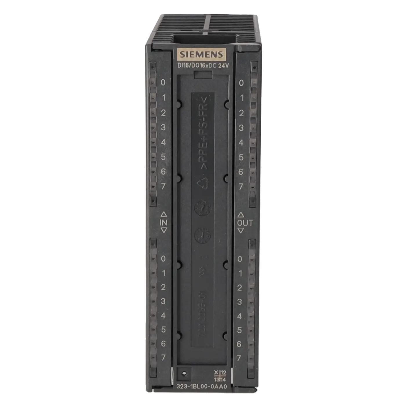
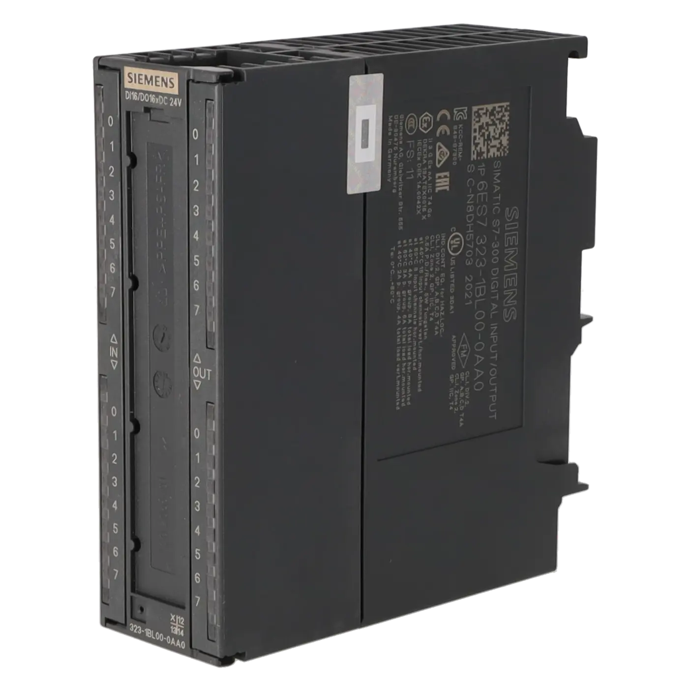
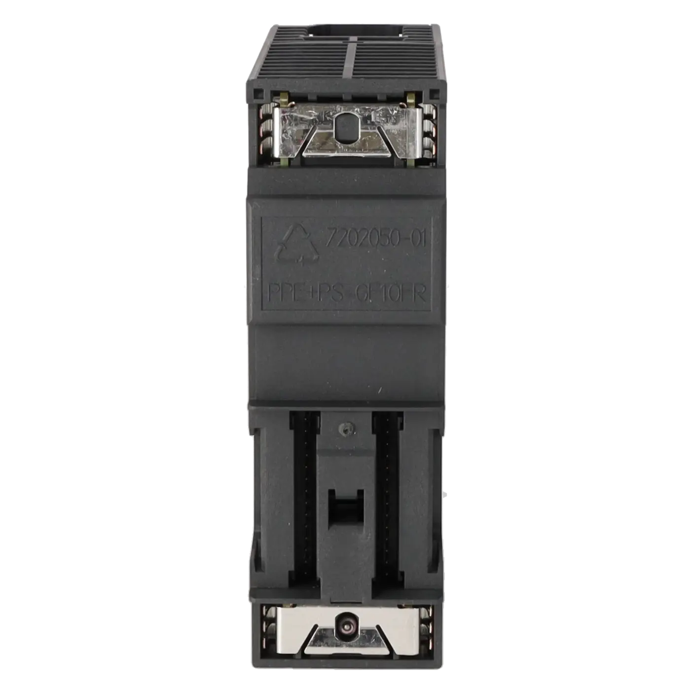
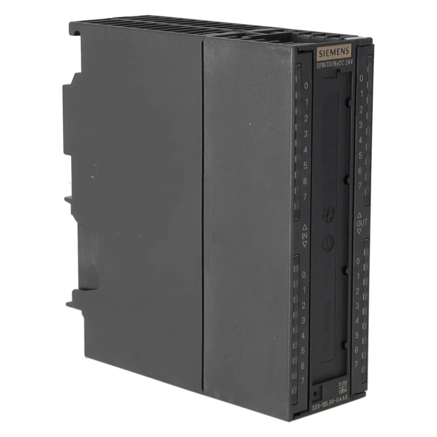
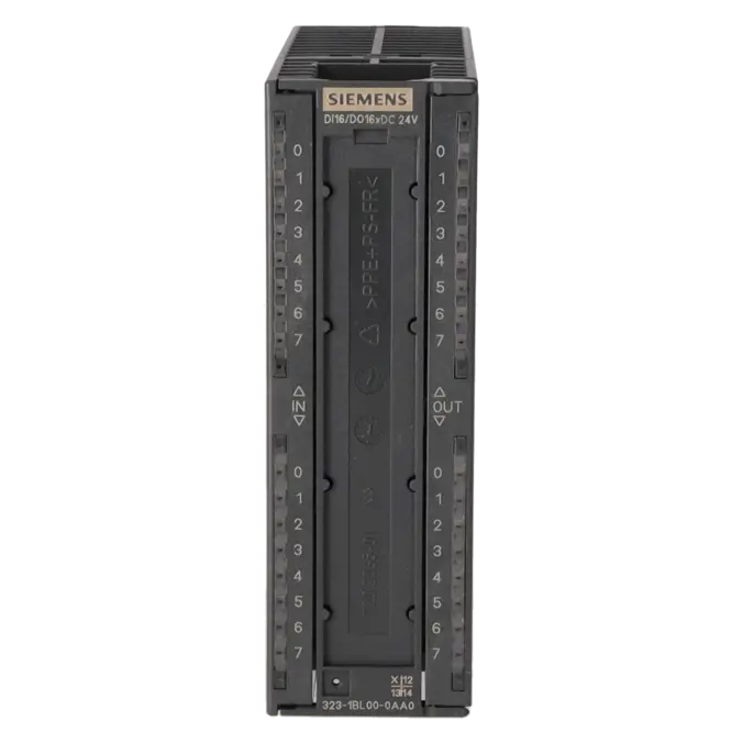
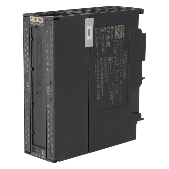
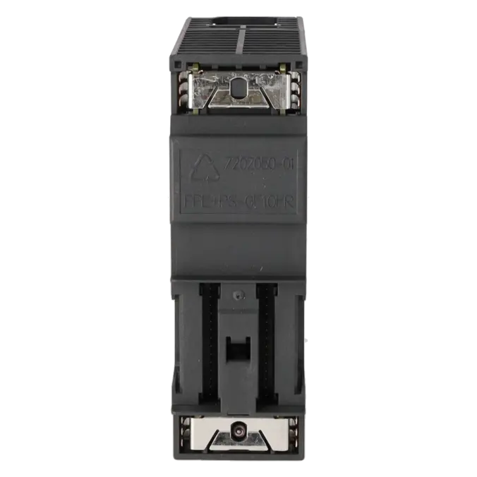
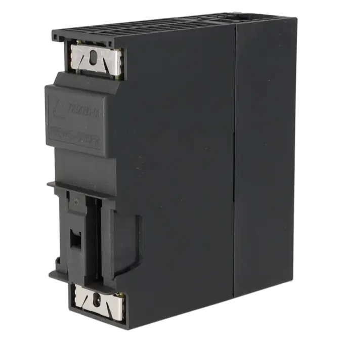
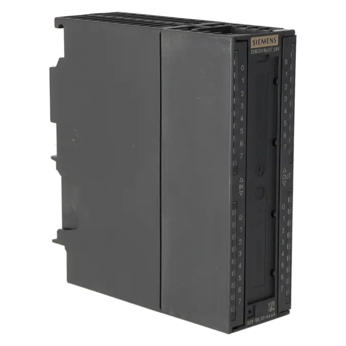
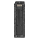
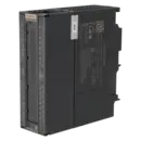
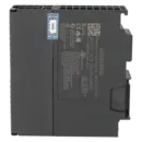
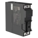
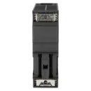
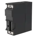
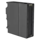
SIMATIC S7-300, DIGITAL MODULE SM 323, ISOLATED, 16 DI AND 16 DO, 24 V DC, 0.5 A, TOTAL CURRENT 4A, 1X 40-POLE
Services for SIEMENS 6ES7323-1BL00-0AA0
Repair
from 426,08 €
to 766,95 €
Replacement
635,28 €
476,46 €
Used
705,87 €
529,40 €
New
784,30 €
588,22 €
SIEMENS |
6ES7323-1BL00-0AA0 –
additional product information
| Delivery information | |||
|---|---|---|---|
| Export identifier | AL: N ECCN: EAR99H | ||
| Net weight | 0.302 | ||
| Quantity | 1 Stück | ||
| Packaging quantity | 1 | ||
| Additional product information | |||
|---|---|---|---|
| Product status | EOP: 2025-10-01 | ||
| EAN | 4025515061120 | ||
| UPC | 662643117950 | ||
| Static lot number | 85389091 | ||
| List indicator | ST73 | ||
| Product group | 4561 | ||
| Country of origin | DE | ||
| Compliance with the substance restrictions according to RoHS directive | Since: 20080331 | ||
| Product classifications | Version | Classification | |
|---|---|---|---|
| eClass | 4 | 27-24-03-04 | |
| eClass | 5.1 | 27-24-22-04 | |
| eClass | 6.0 | 27-24-22-04 | |
| ETIM | 3 | / | |
| ETIM | 4 | EC001419 | |
| ETIM | 5 | EC001419 | |
What is the 6ES7323-1BL00-0AA0 and where is it used?
The 6ES7323-1BL00-0AA0 is a SIMATIC S7-300 SM 323 digital I/O assembly from Siemens. The module combines 16 digital inputs and 16 digital outputs within a single assembly and is designed for 24 V DC signals in conventional machine and plant control systems. Typical applications include conveyor technology, packaging machinery, assembly lines, special-purpose machinery and retrofit projects where existing S7-300 or ET 200M architectures continue to be operated. For maintenance personnel, the assembly is particularly attractive when both sensors and actuators need to be handled without stocking two separate modules. For procurement departments, it is especially relevant when an existing part number must be identified 1:1, sourced at short notice or replaced quickly in the event of a failure.
Overview of the key technical data and what it means
The assembly operates with a 24 V DC load voltage, with a permissible range of 20.4 to 28.8 V DC. The 16 inputs recognise a logic “1” signal between 13 and 30 V, which is important for typical 24 V field signals. The 16 outputs provide 0.5 A per channel, while the total current per group can reach 4 A when mounted horizontally at temperatures up to 40 °C. Additional features include short-circuit protection, a typical power dissipation of 6.5 W, cable lengths of up to 1000 m screened or 600 m unscreened, and a 40-pin front connector. In practical terms, these specifications mean that the module is designed for robust standard digital applications, but loads, wiring, ambient temperature and output grouping must be carefully checked to avoid failures or operation at the limits of the specification.
Product status, life-cycle status and obsolescence
Siemens lists the 6ES7323-1BL00-0AA0 as a spare part, while the Industry Mall identifies its life-cycle status as PM410: Product cancellation, effective from 01 October 2025. The EICHLER product page also shows a product status of EOP: 2025-10-01. For operators, this means that the assembly already falls within the scope of obsolescence management in many facilities, even though it is still technically required. No directly compatible successor is specified by Siemens on the product page itself. However, in the S7-300 to S7-1500 migration guide, Siemens assigns the function to the 6ES7523-1BL00-0AA0. This should be understood as a migration equivalent, not as a simple plug-and-play replacement within an existing S7-300 rack.
Available EICHLER services and when they are relevant
For the 6ES7323-1BL00-0AA0, EICHLER offers repair services, exchange units, used assemblies and new devices. Repair is particularly suitable when a failed assembly is to be retained and professionally refurbished; according to the product page, the service includes technical cleaning, preventive maintenance, comprehensive functional testing and a minimum 24-month warranty. The exchange service is especially valuable during production downtime, as it focuses on the rapid replacement of the defective unit with an available substitute. A used assembly is a practical option for budget-conscious procurement or spare-parts stock building, whereas a new device is better suited to a standardised spare-parts strategy with the most original equipment status possible. In addition, a digital input/output test report can be ordered, providing added value for quality-sensitive systems and maintenance activities requiring formal documentation.
| Attribute | Value |
|---|---|
| Supply voltage | |
| Load voltage L+ | |
| ● Rated value (DC) | 24 V |
| ● permissible range, lower limit (DC) | 20.4 V |
| ● permissible range, upper limit (DC) | 28.8 V |
| Input current | |
| from load voltage L+ (without load), max. | 80 mA |
| from backplane bus 5 V DC, max. | 80 mA |
| Power loss | |
| Power loss, typ. | 6.5 W |
| Digital inputs | |
| Number of digital inputs | 16 |
| Input characteristic curve in accordance with IEC 61131, type 1 | Yes |
| Number of simultaneously controllable inputs | |
| horizontal installation | |
| — up to 40 °C, max. | 16 |
| — up to 60 °C, max. | 8 |
| vertical installation | |
| — up to 40 °C, max. | 16 |
| Input voltage | |
| ● Type of input voltage | DC |
| ● Rated value (DC) | 24 V |
| ● for signal "0" | -30 to +5 V |
| ● for signal "1" | 13 to 30V |
| Input current | |
| ● for signal "1", typ. | 7 mA |
| Input delay (for rated value of input voltage) | |
| for standard inputs | |
| — at "0" to "1", min. | 1.2 ms |
| — at "0" to "1", max. | 4.8 ms |
| — at "1" to "0", min. | 1.2 ms |
| — at "1" to "0", max. | 4.8 ms |
| Cable length | |
| ● shielded, max. | 1 000 m |
| ● unshielded, max. | 600 m |
| Digital outputs | |
| Number of digital outputs | 16 |
| Short-circuit protection | Yes |
| ● Response threshold, typ. | 1 A |
| Limitation of inductive shutdown voltage to | L+ (-48 V) |
| Controlling a digital input | Yes |
| Switching capacity of the outputs | |
| ● on lamp load, max. | 5 W |
| Load resistance range | |
| ● lower limit | 48 Ω |
| ● upper limit | 4 kΩ |
| Output voltage | |
| ● for signal "1", min. | L+ (-0.8 V) |
| Output current | |
| ● for signal "1" rated value | 0.5 A |
| ● for signal "1" permissible range, min. | 5 mA |
| ● for signal "1" permissible range, max. | 0.6 A |
| ● for signal "1" minimum load current | 5 mA |
| ● for signal "0" residual current, max. | 0.5 mA |
| Output delay with resistive load | |
| ● "0" to "1", max. | 100 µs |
| ● "1" to "0", max. | 500 µs |
| Parallel switching of two outputs | |
| ● for uprating | No |
| ● for redundant control of a load | Yes; only outputs of the same group |
| Switching frequency | |
| ● with resistive load, max. | 100 Hz |
| ● with inductive load, max. | 0.5 Hz |
| ● on lamp load, max. | 100 Hz |
| Total current of the outputs (per group) | |
| horizontal installation | |
| — up to 40 °C, max. | 4 A |
| — up to 60 °C, max. | 3 A |
| vertical installation | |
| — up to 40 °C, max. | 2 A |
| Cable length | |
| ● shielded, max. | 1 000 m |
| ● unshielded, max. | 600 m |
| Encoder | |
| Connectable encoders | |
| ● 2-wire sensor | Yes |
| — permissible quiescent current (2-wire sensor), max. | 1.5 mA |
| Interrupts/diagnostics/status information | |
| Alarms | No |
| Diagnostics function | No |
| Diagnostics indication LED | |
| ● Status indicator digital input (green) | Yes |
| ● Status indicator digital output (green) | Yes |
| Potential separation | |
| Potential separation digital inputs | |
| ● between the channels | Yes |
| ● between the channels, in groups of | 16 |
| ● between the channels and backplane bus | Yes; Optocoupler |
| Potential separation digital outputs | |
| ● between the channels | Yes |
| ● between the channels, in groups of | 8 |
| ● between the channels and backplane bus | Yes; Optocoupler |
| Isolation | |
| Isolation tested with | 500 V DC |
| Connection method | |
| required front connector | 40-pin |
| Dimensions | |
| Width | 40 mm |
| Height | 125 mm |
| Depth | 120 mm |
| Weights | |
| Weight, approx. | 260 g |
| Fault description | Possible solution |
|---|---|
| Why does the output not switch despite being enabled by the program? | A common cause is a missing L+ load supply for the output side or an improperly connected return conductor. The SM 323 switches the output voltage relative to the applied load supply; if no stable 24 V DC supply is present, the actuator will remain inactive despite the program status. In addition, check that M/0 V is continuously connected and verify that there are no wiring faults at the front connector. |
| Why does an output respond only briefly or not at all under load? | The load side should be checked for overcurrent, short circuits or an unsuitable load type. The module is designed for 0.5 A per channel and features short-circuit protection with a typical response threshold of 1 A. Lamp loads are also subject to limitations. If the load limit is exceeded or a wiring fault is present, the channel will not operate reliably. In addition, the total current per output group depends on the mounting position and ambient temperature. |
| Why does the assembly not reliably detect a 24 V input signal? | The key factor is whether the required voltage is actually present at the input. Siemens specifies a logic “1” signal range of 13 to 30 V. If the signal falls below this range or the appropriate reference potential is missing, the input will remain at logic “0”. For sensors, it should also be verified that the sensor type, switching output and wiring configuration are compatible with the assembly. Particular attention should be paid to the permissible quiescent current when using 2-wire sensors. |
| Why can I not find a clear diagnostic alarm even though the inputs or outputs are not working? | According to Siemens, this assembly provides no diagnostic functions and no diagnostic alarms; only green status LEDs for the inputs and outputs are available. Troubleshooting must therefore be carried out using the LED status, voltage measurements, address verification and program checks. For outputs that have no effect, particular attention should be paid to the hardware configuration, duplicate address assignments and the actual output address being used. |
| Why does the assembly not operate as expected after replacement? | A common reason is an incorrect or improperly rewired front connector. According to Siemens, the 6ES7323-1BL00-0AA0 requires a 40-pin front connector. If the wiring is not transferred 1:1 during replacement or an incompatible connector is used, individual channels may appear non-functional even though the module itself is operating correctly. |
Is the 6ES7323-1BL00-0AA0 still active or has it been discontinued?
The assembly is no longer in the active product lifecycle. Siemens classifies it as a spare part and lists the status Product Cancellation, effective from 01 October 2025. The EICHLER product page reflects this with the status EOP: 2025-10-01. For operators, this means that the part number remains important for service and spare-parts management, but it should no longer be regarded as a long-term procurement standard for new projects. For existing systems, the key consideration is whether to build up spare-part stock, hold exchange units or prepare migration strategies.
Which front connector is required for the 6ES7323-1BL00-0AA0?
This assembly requires a 40-pin front connector. This is important for both procurement and maintenance, as replacing a module requires not only the correct module part number but also the correct connector technology. If the appropriate front connector is unavailable or the existing wiring is damaged, downtime may be unnecessarily extended. As part of a spare-parts strategy, the correct front connector should therefore ideally be documented alongside the assembly or kept in stock together with it.
Can I use the 6ES7323-1BL00-0AA0 in an ET 200M station?
Yes. Functionally, the assembly belongs to the S7-300 / ET 200M platform and is described by Siemens in the context of the ET 200M distributed I/O system. However, the actual application must be compatible with the installed interface module (IM), the specific station configuration and the existing hardware architecture. This is particularly important when not only replacing a module but also modernising or expanding an entire distributed I/O station.
Is there a direct successor to the 6ES7323-1BL00-0AA0?
A direct plug-compatible successor is not identified in the available Siemens primary documentation for this specific S7-300 assembly. However, within the S7-300 to S7-1500 migration guide, Siemens identifies the 6ES7523-1BL00-0AA0 as the functional migration equivalent. This distinction is important for decision-makers: organisations seeking only to maintain an existing installation will often be better served by repair, exchange services or spare-part stock building. Those planning a strategic upgrade should evaluate migration to a new control platform as a separate project.
When is repair more appropriate than exchange or purchasing a new unit?
Repair is particularly appropriate when the existing assembly already fits the installation, needs to be returned to service quickly and the original hardware configuration must remain unchanged. An exchange unit is often the better choice during critical production downtime, where restoring availability is the primary objective. A used unit is suitable for cost-conscious spare-parts management or stock building, while a new unit is attractive for companies wishing to remain as close as possible to the original equipment status despite the obsolescence of S7-300 components. On the EICHLER product page, these options are available with different delivery times and equipment conditions to support professional B2B procurement.
Which technical points should I verify before placing an order?
Before ordering, at a minimum, the following should be verified:
- Part number: 6ES7323-1BL00-0AA0
- Signal type: 24 V DC
- Configuration: 16 digital inputs / 16 digital outputs
- Output current: 0.5 A per channel
- Total group current: 4 A
- Front connector: 40-pin
- Whether the application is installed in an S7-300 or ET 200M environment
It is equally important to verify the actual load per channel, the grouping of outputs and the existing wiring configuration. With obsolete products, this level of verification saves time and helps avoid incorrect orders, unnecessary modifications and unexpected commissioning risks.