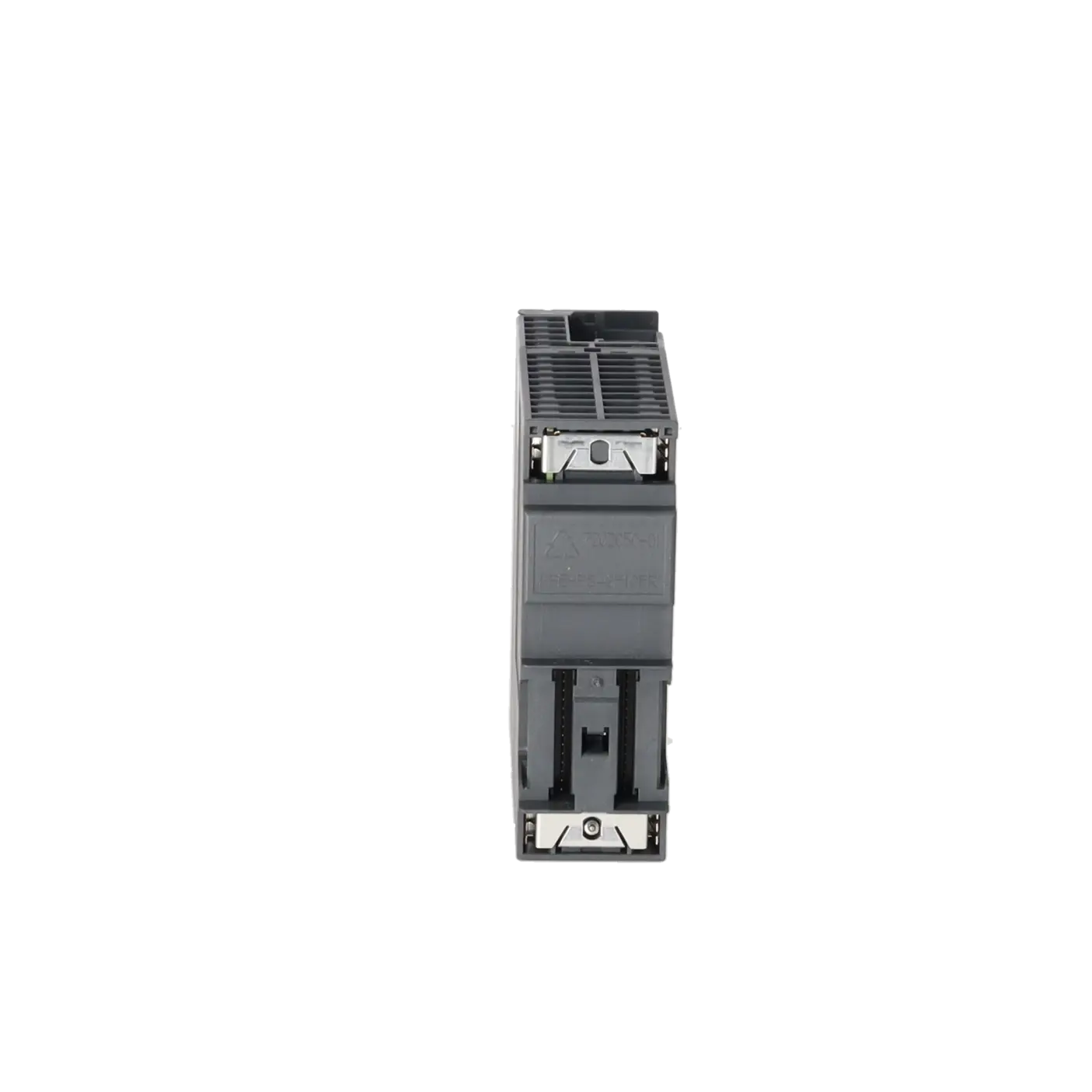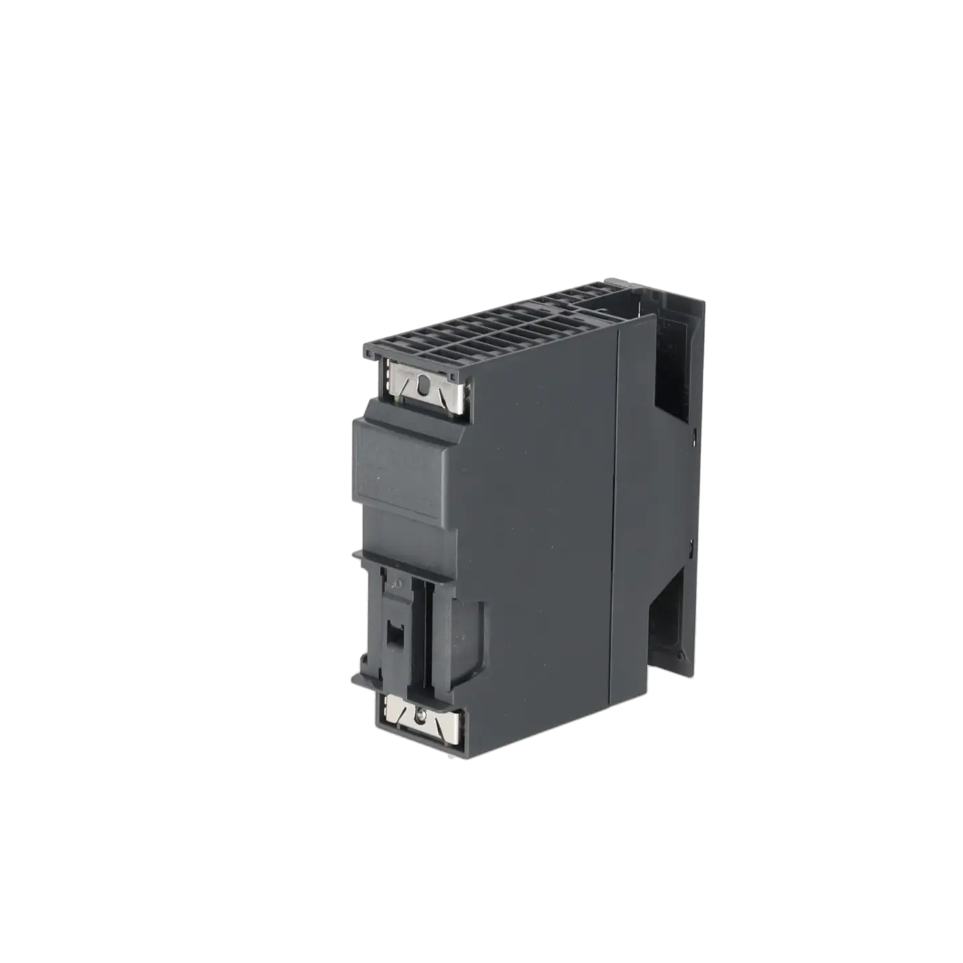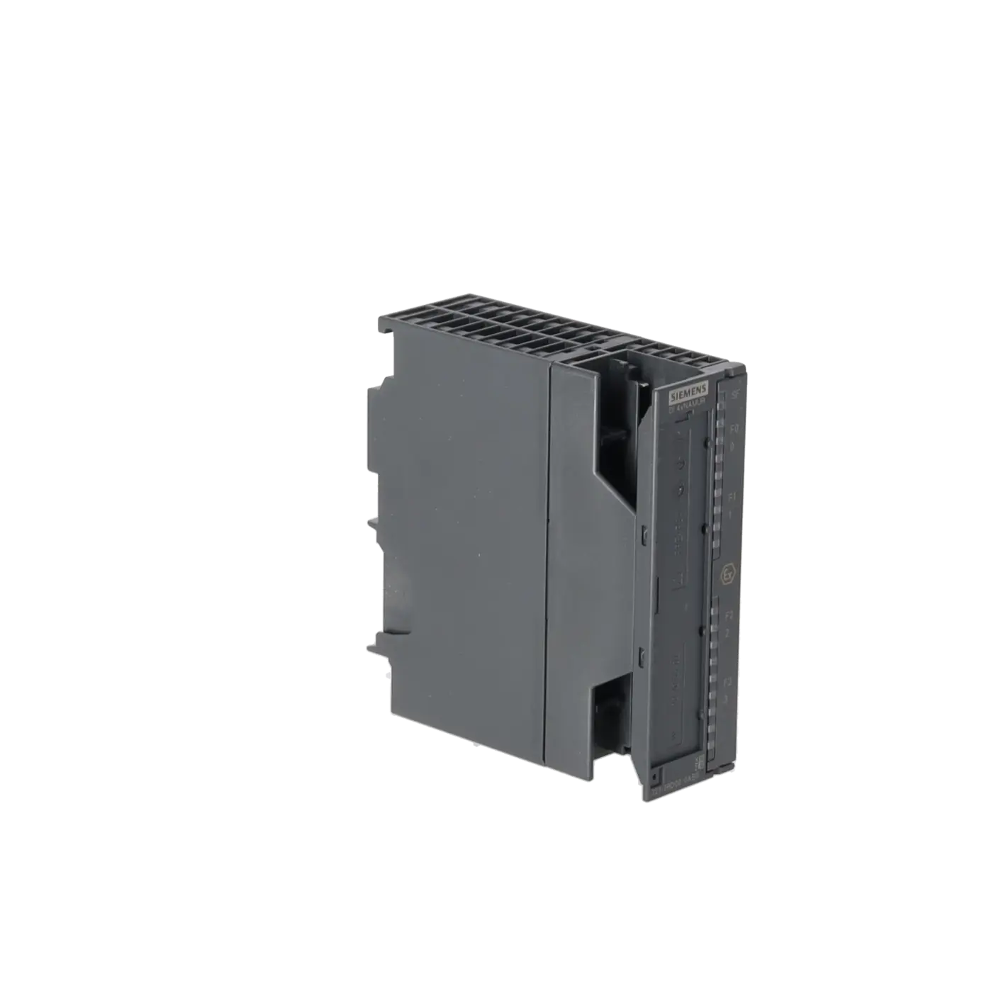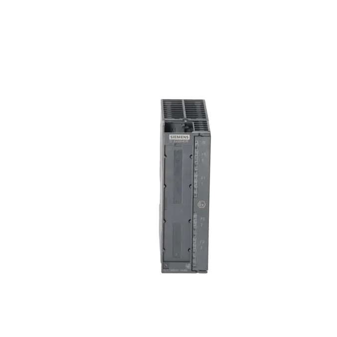
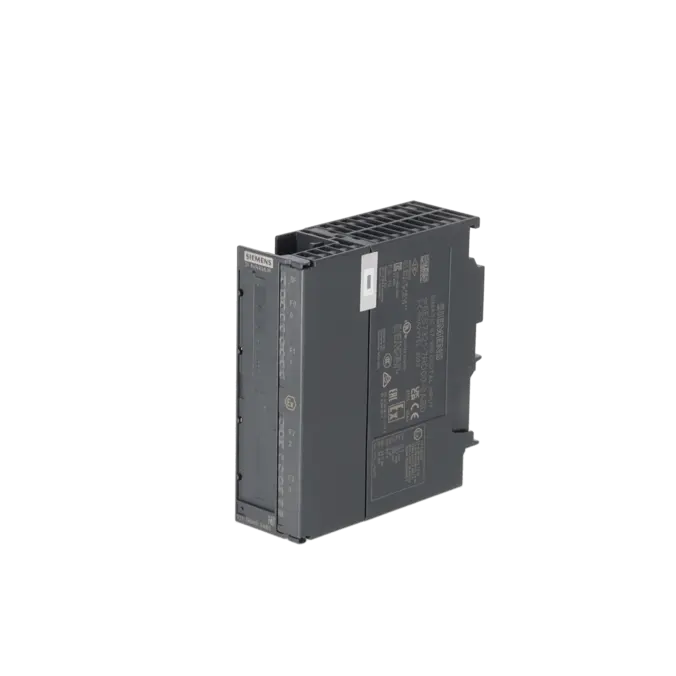
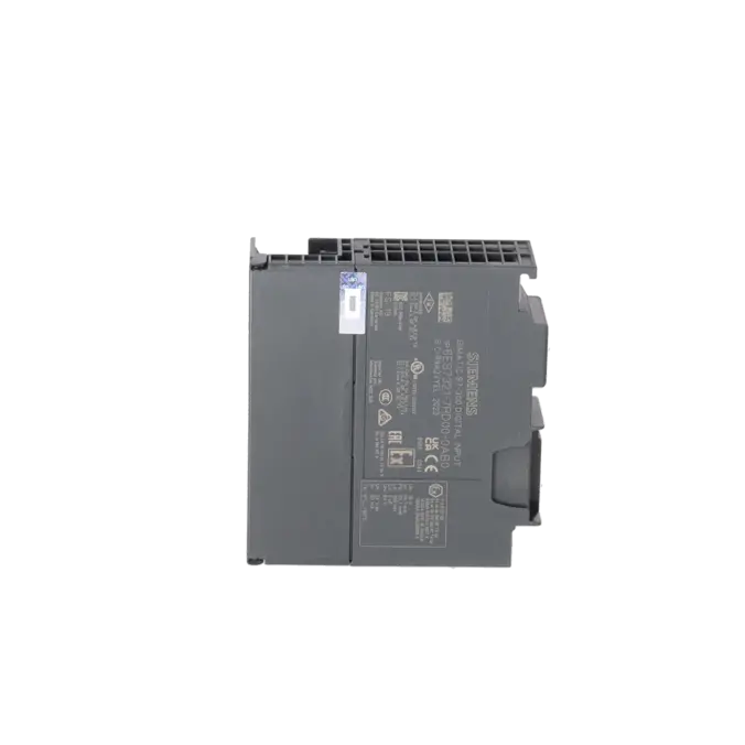
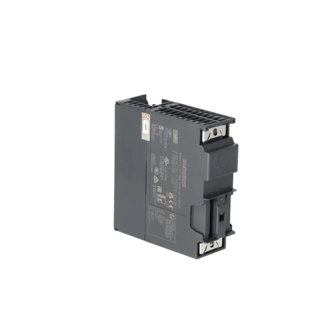
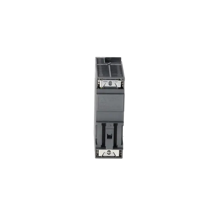
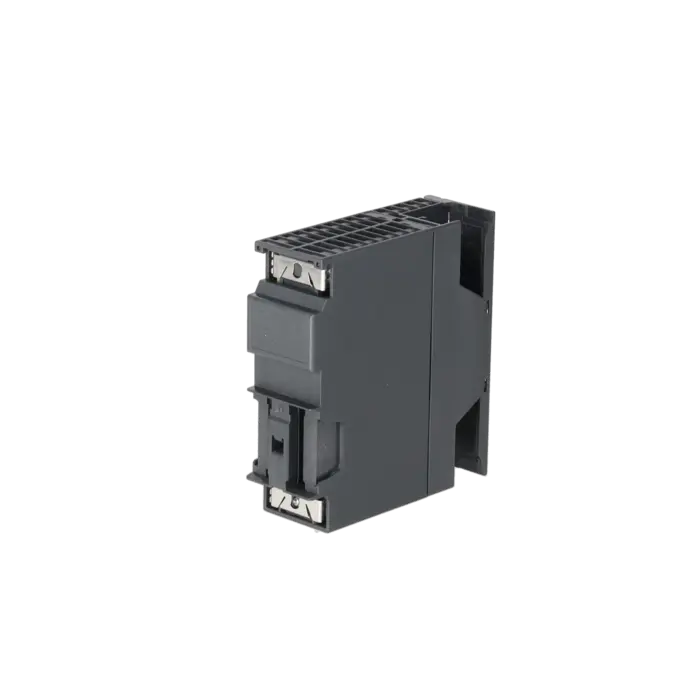
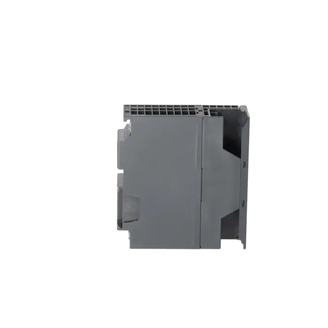
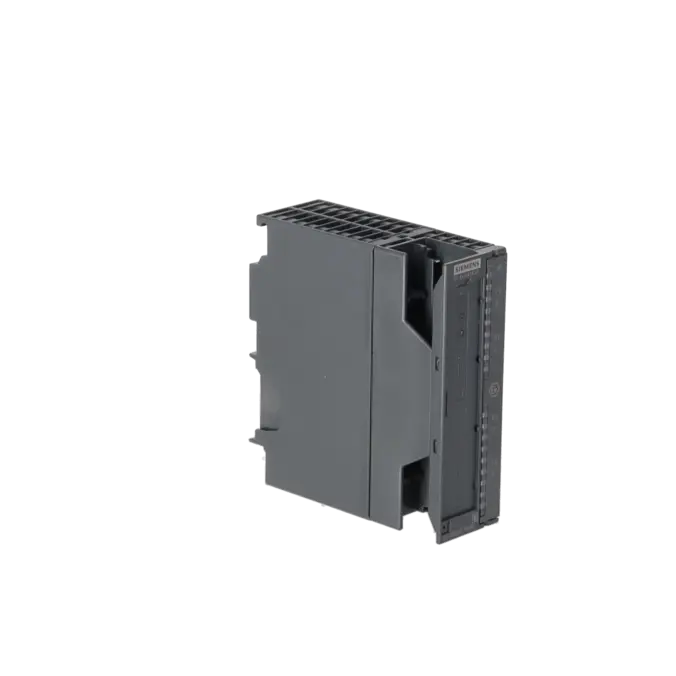

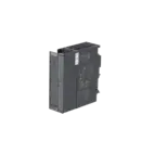
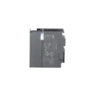
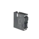
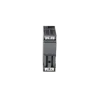
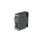


SIEMENS 6ES7321-7RD00-0AB0
-
SIEMENS | PLC Controls | Digital Input / Output Modules
- EICHLER-art.no.: K0118539
- EAN: 4025515060871
- UPC: 662643230727
Product description
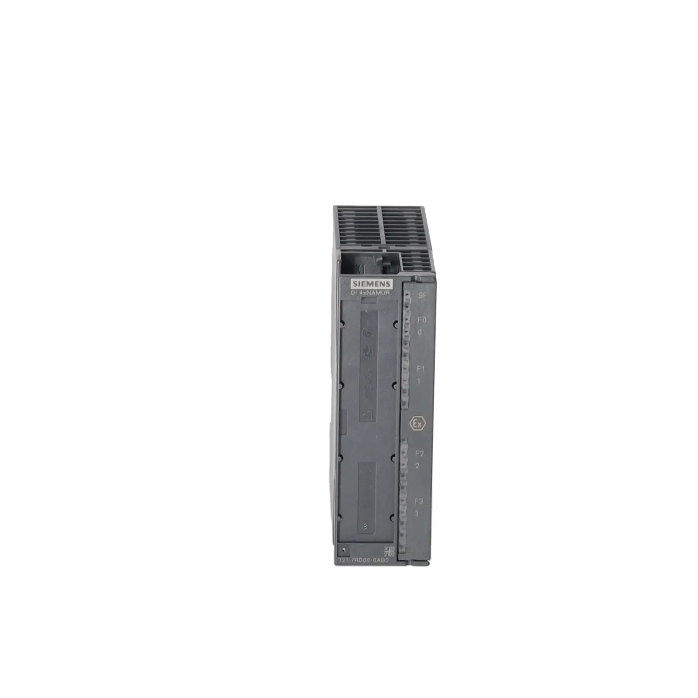
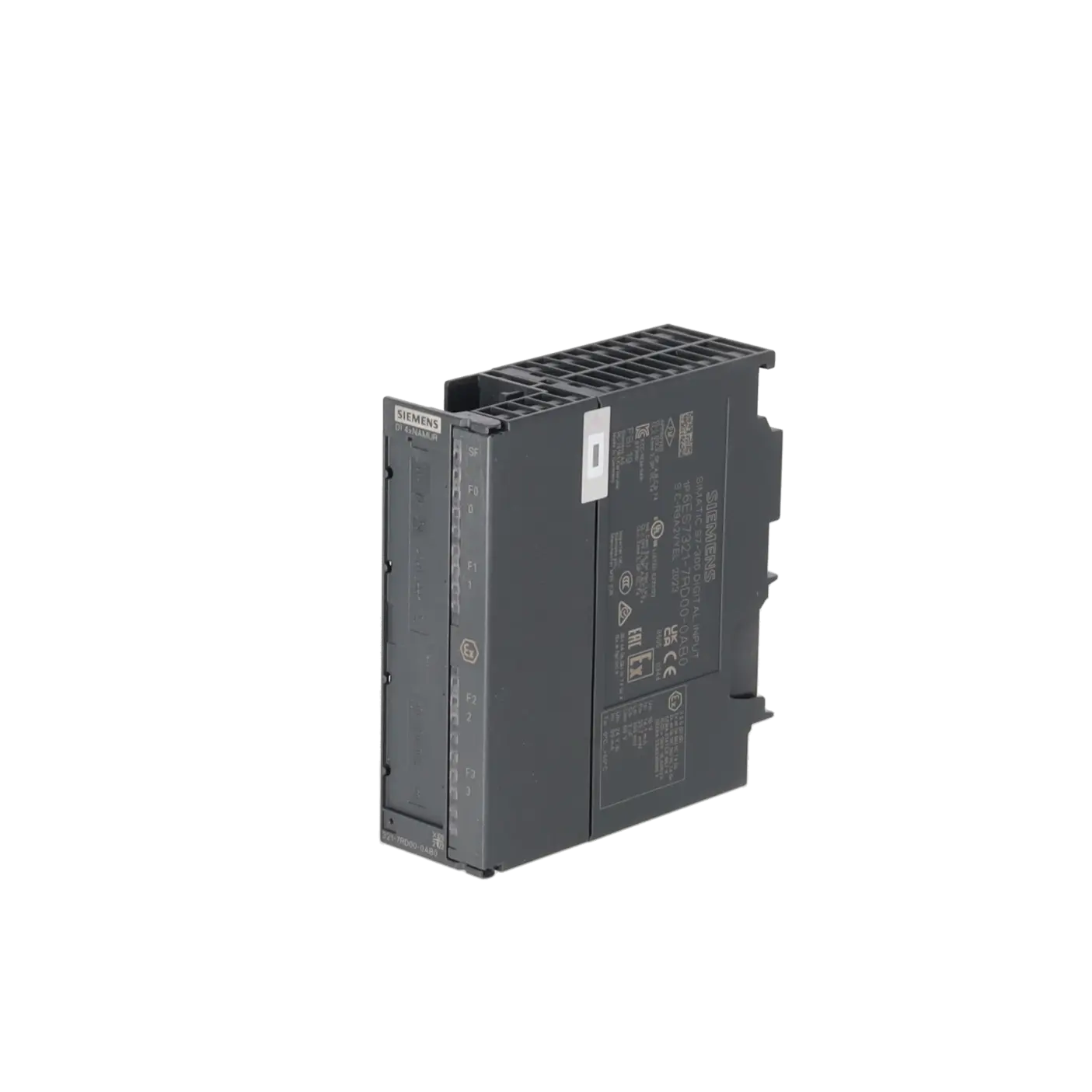
SIMATIC S7, DIGITAL INPUT SM 321, ISOLATED, 4 DI; 24 V DC, NAMUR/DIN 19234, FOR SIGNALS FROM THE HAZARDOUS AREA, DIAGNOSTICS-CAPABLE, PTB TESTED
Services for SIEMENS 6ES7321-7RD00-0AB0
Repair
from 612,85 €
to 937,30 €
Replacement
Used
648,91 €
486,68 €
New
721,00 €
540,75 €
SIEMENS |
6ES7321-7RD00-0AB0 –
additional product information
| Delivery information | |||
|---|---|---|---|
| Export identifier | AL: N ECCN: EAR99H | ||
| Net weight | 0.34 | ||
| Quantity | 1 Stück | ||
| Packaging quantity | 1 | ||
| Additional product information | |||
|---|---|---|---|
| Product status | EOP: 2025-10-01 | ||
| EAN | 4025515060871 | ||
| UPC | 662643230727 | ||
| Static lot number | 85389091 | ||
| List indicator | STPCS7 | ||
| Product group | 4428 | ||
| Country of origin | DE | ||
| Compliance with the substance restrictions according to RoHS directive | Since: 20051215 | ||
| Product classifications | Version | Classification | |
|---|---|---|---|
| eClass | 4 | 27-24-03-04 | |
| eClass | 5.1 | 27-24-22-04 | |
| eClass | 6.0 | 27-24-22-04 | |
| ETIM | 3 | / | |
| ETIM | 4 | EC001419 | |
| ETIM | 5 | EC001419 | |
What is the 6ES7321-7RD00-0AB0 and where is it used?
The 6ES7321-7RD00-0AB0 is a SIMATIC S7 SM 321 digital input assembly from Siemens featuring 4 isolated NAMUR digital inputs for 24 V DC applications. The module is designed for signals originating from hazardous (Ex) areas, supports diagnostic functions and is PTB-certified. Typical applications include process industries, chemical plants, energy generation, water and wastewater treatment facilities, and other industrial environments where NAMUR two-wire sensors or contact transmitters from hazardous areas must be safely integrated into S7-300 or ET 200M systems. For maintenance personnel, the module is particularly relevant where reliable signal acquisition, advanced diagnostics and proper isolation of input circuits are essential.
Overview of the key technical data and what it means
The assembly operates with a 24 V supply voltage and provides 8.2 V at the inputs via an internal supply circuit. It supports 4 NAMUR inputs. Input delay times of 0.1 ms, 0.5 ms, 3 ms, 15 ms and 20 ms can be parameterised; with a setting of 0.1 ms, NAMUR input frequencies of up to 2 kHz are possible. The maximum unscreened cable length is 200 m. Other important practical features include diagnostic capability, an SF (System Fault) LED, channel-specific fault indication and hazardous-area parameters such as Uo = 10 V, Io = 14.1 mA, Po = 33.7 mW, Co = 3 µF and Lo = 100 mH. These specifications are important when selecting sensors, designing wiring, defining response times and validating the hazardous-area concept of the installation.
Product status, life-cycle status and obsolescence
The EICHLER product page lists the 6ES7321-7RD00-0AB0 with the status EOP: 2025-10-01. Siemens also classifies the assembly as a spare part, while lifecycle information identifies it as Product Lifecycle: Product Cancellation. In addition, EICHLER explicitly includes this part number in its overview of SIMATIC S7-300 and ET 200M assemblies discontinued as of 01 October 2025. For modernisation projects, it is important to note that Siemens identifies the 6DL1131-6TD00-0HX1 Ex-DI 4xNAMUR in the current ET 200M to ET 200SP HA I/O Comparison Guide as the corresponding migration module. This should be regarded as a migration reference, not as a verified 1:1 replacement for existing installations.
Available EICHLER services and when they are relevant
For operators of existing S7-300 or ET 200M installations, the availability of repair, exchange, used and new equipment is particularly valuable. EICHLER currently offers repair services within 2–5 days, including technical cleaning, preventive maintenance, comprehensive functional testing and a minimum 24-month warranty. In addition, used assemblies are available with a delivery time of 3–5 days, new devices with a delivery time of 1–3 days, while exchange services are available on request. These options are particularly relevant when the objective is to avoid downtime, control CAPEX and inventory costs, or ensure the continued operation of a discontinued automation system for many years to come.
| Attribute | Value |
|---|---|
| Supply voltage | |
| Load voltage L+ | |
| ● Rated value (DC) | 24 V |
| ● Reverse polarity protection | Yes |
| Input current | |
| from load voltage L+ (without load), max. | 50 mA |
| from backplane bus 5 V DC, max. | 80 mA |
| Encoder supply | |
| Type of output voltage | via the inputs |
| Power loss | |
| Power loss, typ. | 1.1 W |
| Digital inputs | |
| Number of digital inputs | 4 |
| Number of NAMUR inputs | 4 |
| Input voltage | |
| ● Type of input voltage | DC |
| ● Rated value (DC) | 8.2 V; from internal power circuit supply |
| Input current | |
| ● on wire-break, max. | 0.1 mA |
| ● on short-circuit, max. | 8.5 mA |
| for NAMUR encoders | |
| — for signal "0", min. | 0.35 mA |
| — for signal "0", max. | 1.2 mA |
| — for signal "1", min. | 2.1 mA |
| — for signal "1", max. | 7 mA |
| Input delay (for rated value of input voltage) | |
| ● Input frequency (with a time delay of 0.1 ms), max. | 2 kHz |
| for NAMUR inputs | |
| — parameterizable | Yes; 0.1 / 0.5 / 3 / 15 / 20 ms (plus 0.25 ms preparation time) |
| Cable length | |
| ● unshielded, max. | 200 m |
| Encoder | |
| Connectable encoders | |
| ● NAMUR encoder | Yes; Two-wire connection |
| Interrupts/diagnostics/status information | |
| Diagnostics function | Yes |
| Diagnoses | |
| ● Diagnostic information readable | Yes |
| Diagnostics indication LED | |
| ● Group error SF (red) | Yes |
| ● Status indicator digital input (green) | Yes |
| ● Channel fault indicator F (red) | Yes |
| Ex(i) characteristics | |
| Module for Ex(i) protection | Yes |
| maximum values for connecting terminals for gas group IIC | |
| ● Uo (no-load voltage), max. | 10 V |
| ● Io (short-circuit current), max. | 14.1 mA |
| ● Po (power output), max. | 33.7 mW |
| ● Co (permissible external capacity), max. | 3 µF |
| ● Lo (permissible external inductivity), max. | 100 mH |
| Potential separation | |
| Potential separation digital inputs | |
| ● between the channels | Yes; 60 V DC/30 V AC when used in the hazardous area; 400 V DC/250 V AC when used in NON-hazardous area |
| ● between the channels, in groups of | 1 |
| ● between the channels and backplane bus | Yes; 60 V DC/30 V AC when used in the hazardous area; 400 V DC/250 V AC when used in NON-hazardous area |
| ● Between the channels and load voltage L+ | Yes; 60 V DC/30 V AC when used in the hazardous area; 400 V DC/250 V AC when used in NON-hazardous area |
| Standards, approvals, certificates | |
| Use in hazardous areas | |
| ● ATEX marking | ATEX II 3 G (2) GD Ex nA [ib Gb] [ib IIIC Db] IIC T4 Gc |
| ● FM marking | Class II, Division 2, Group A, B, C, D T4 |
| ● Test number PTB | Ex-96.D.2094X |
| Ambient conditions | |
| Ambient temperature during operation | |
| ● max. | 60 °C |
| Connection method | |
| required front connector | 20-pin |
| Dimensions | |
| Width | 40 mm |
| Height | 125 mm |
| Depth | 120 mm |
| Weights | |
| Weight, approx. | 230 g |
| Fault description | Possible solution |
|---|---|
| Why does the 6ES7321-7RD00-0AB0 report a wire break on one channel? | The assembly monitors the NAMUR input for wire break on a channel-specific basis. First check the sensor, terminals, wire interruptions and the complete two-wire circuit. For NAMUR sensors, the module typically expects 0.35 to 1.2 mA for signal 0 and 2.1 to 7 mA for signal 1; if the current is outside this range, the diagnosis is triggered. Read out the detailed diagnostics in STEP 7 and, if required, use SFC 59 or SFC 53 for the module data. |
| Why does the SM 321 indicate a short circuit to M? | This diagnosis indicates an unwanted connection between the input circuit and M. Check the wiring, shield connection, moisture in the terminal area, damaged sensor cables and incorrectly connected NAMUR sensors. Check the affected channel individually and disconnect the field side and the assembly one after the other as a test in order to clearly isolate the fault location. The assembly reports short circuits on a channel-specific or channel-group-specific basis and provides diagnostic information in STEP 7. |
| Why does the 6ES7321-7RD00-0AB0 report incorrect parameters in the assembly or assembly not parameterised? | Compare the order number, slot assignment and parameterisation configured in STEP 7 with the assembly actually installed. The SM 321 is parameterised in STEP 7; static parameters are stored in the CPU and transferred to the assembly when the CPU changes from STOP to RUN. After replacing a module or changing the hardware configuration, check the hardware configuration and diagnostic buffer, then reload the configuration cleanly. |
| Why does the SF LED remain lit after reparameterisation? | Siemens describes that, for this assembly, the SF LED may remain lit after reparameterisation even though the assembly is already operating correctly, if a diagnosis was still pending before reparameterisation. Therefore, first check whether there is still an active channel fault or module fault, read out the diagnostic buffer and, where possible, only reparameterise once no active diagnosis is still pending. This helps avoid follow-up alarms and unnecessary troubleshooting. |
| Why do I not see wire break or short circuit directly in the input byte? | With this assembly, diagnostics do not run via an additional status bit in the normal process image as they do with some other NAMUR assemblies. In practice, the message is handled via diagnostic interrupt and system diagnostics. For evaluation, OB82 as well as the diagnostic functions in STEP 7 or SFC 59/SFC 53 are therefore helpful. This behaviour has also been discussed in a PLC forum in connection with the 6ES7321-7RD00-0AB0. |
Which sensors can be connected to the 6ES7321-7RD00-0AB0?
The assembly is designed for NAMUR sensors with a two-wire connection and can also be operated with suitable contact transmitters. The key requirement is that the sensor characteristics are compatible with NAMUR signal evaluation and that the assembly's intrinsically safe Ex(i) limits are observed. For plant operation, this means that before replacing sensors or carrying out retrofit projects, sensor current, protection concept, cable length and parameterisation should always be considered together. This helps prevent false diagnostics, implausible switching states and unnecessary channel faults.
Can I use the 6ES7321-7RD00-0AB0 in S7-300 and ET 200M systems?
Yes. Siemens lists the assembly within both the S7-300 and ET 200M Ex I/O environments. This makes it suitable for both centralised and distributed architectures within these platform families, provided that the configured slot assignments, I/O structure and hazardous-area installation requirements are observed. For existing systems, this is particularly important because the module is often found in long-established installations where obtaining an identical or at least system-compatible replacement can significantly reduce downtime.
How do I correctly read the diagnostic messages of the 6ES7321-7RD00-0AB0?
For basic diagnostics, the STEP 7 system diagnostics are usually sufficient. If diagnostic interrupts are enabled, the CPU typically processes them via OB82. For detailed module information, Siemens recommends SFC 59 and SFC 53; in practical applications, SFC 51 and SFC 52 are also commonly used as diagnostic tools. For maintenance personnel, this is the most reliable way to evaluate wire breaks, short circuits and parameterisation faults on a channel-specific basis rather than relying solely on LED indications or the standard process image.
Has the 6ES7321-7RD00-0AB0 been discontinued, and what does this mean for the spare-parts strategy?
Yes. According to EICHLER, this part number belongs to the group of SIMATIC S7-300 and ET 200M assemblies entering the discontinuation phase from 01 October 2025. At the same time, Siemens still lists it as a spare part, while lifecycle information references Product Cancellation. For procurement and production teams, this means that supply is not immediately ending, but procurement risks, price volatility and delivery-time uncertainty will typically increase over time. As a result, organisations should establish an active spare-parts strategy, define repair processes and evaluate modernisation options.
Is there a current migration option for this module?
Yes. In the current ET 200M to ET 200SP HA comparison guide, Siemens identifies the 6DL1131-6TD00-0HX1 Ex-DI 4xNAMUR as the migration reference for the 6ES7321-7RD00-0AB0. This is particularly relevant for operators planning a process-oriented modernisation programme and wishing to reduce dependency on the ET 200M platform. However, this assignment does not replace a full engineering assessment. Wiring, base units, station architecture, parameterisation and the overall system environment must be thoroughly reviewed before any migration is implemented.
Can I use the assembly in redundant hazardous-area applications?
Caution is required here. Siemens documents that the 6ES7321-7RD00-0AB0 must not be used in redundant operation within hazardous-area applications. For operators of H-systems or other high-availability process plants, this is an important consideration during system design. Where both redundancy and hazardous-area compliance are required, the architecture should be evaluated at an early stage against current Siemens platforms and suitable I/O alternatives.
Where can I obtain or repair a 6ES7321-7RD00-0AB0 at short notice?
According to the EICHLER product page, the assembly is currently available as repair, exchange, used and new equipment. Indicative lead times are 2–5 days for repair, 3–5 days for used equipment and 1–3 days for new equipment, while the exchange service is available on request. For procurement and maintenance teams, this flexibility is valuable because it allows a choice between rapid restoration of availability, cost optimisation and a long-term spare-parts strategy. Particularly for discontinued S7-300 and ET 200M assemblies, this operational flexibility is often more important than the theoretical lifecycle status alone.