SIEMENS 6ES7317-7TK10-0AB0
-
SIEMENS | PLC Controls | Central Processing Units
- EICHLER-art.no.: K0339818
- EAN: 4025515082545
- UPC: 887621409296
Product description
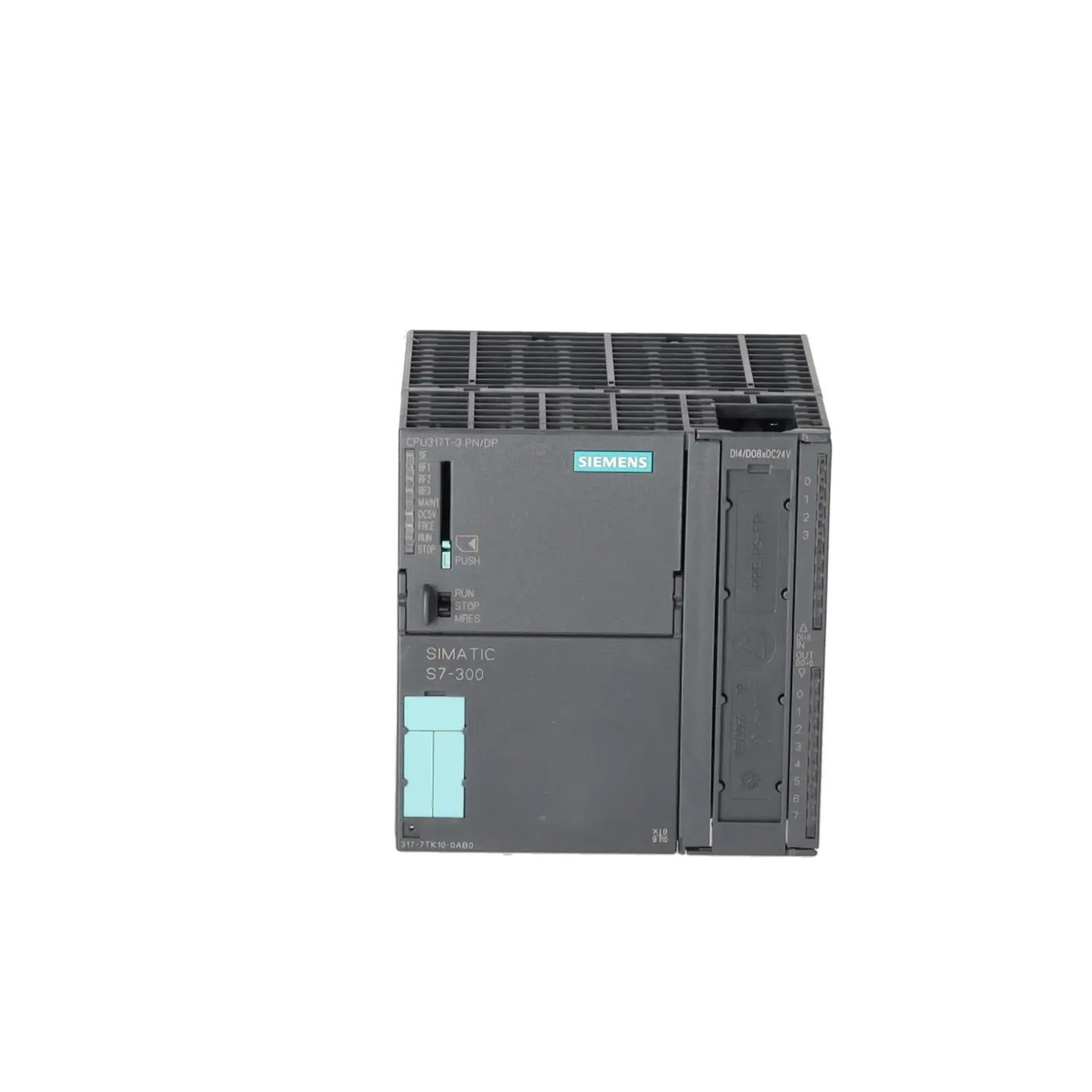
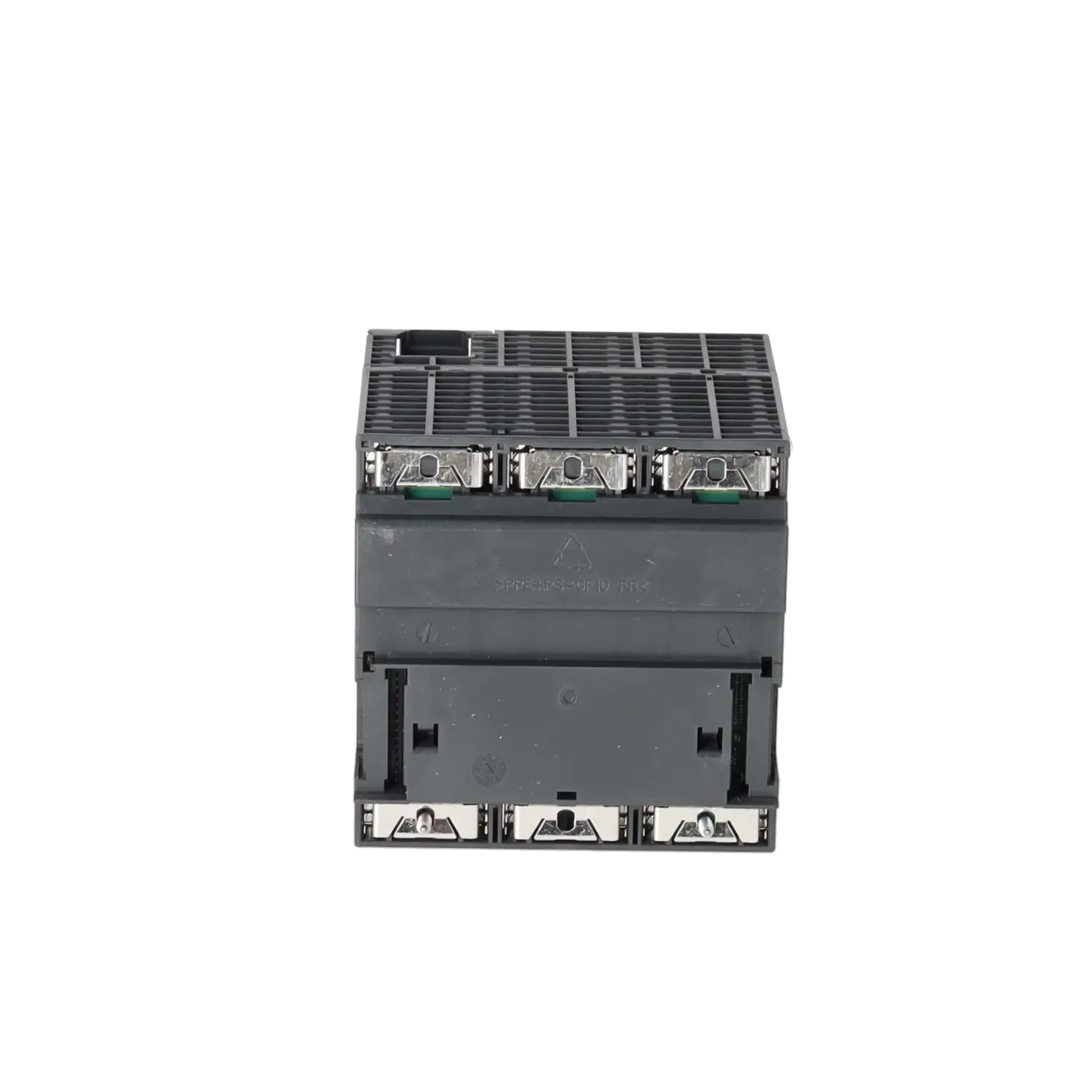
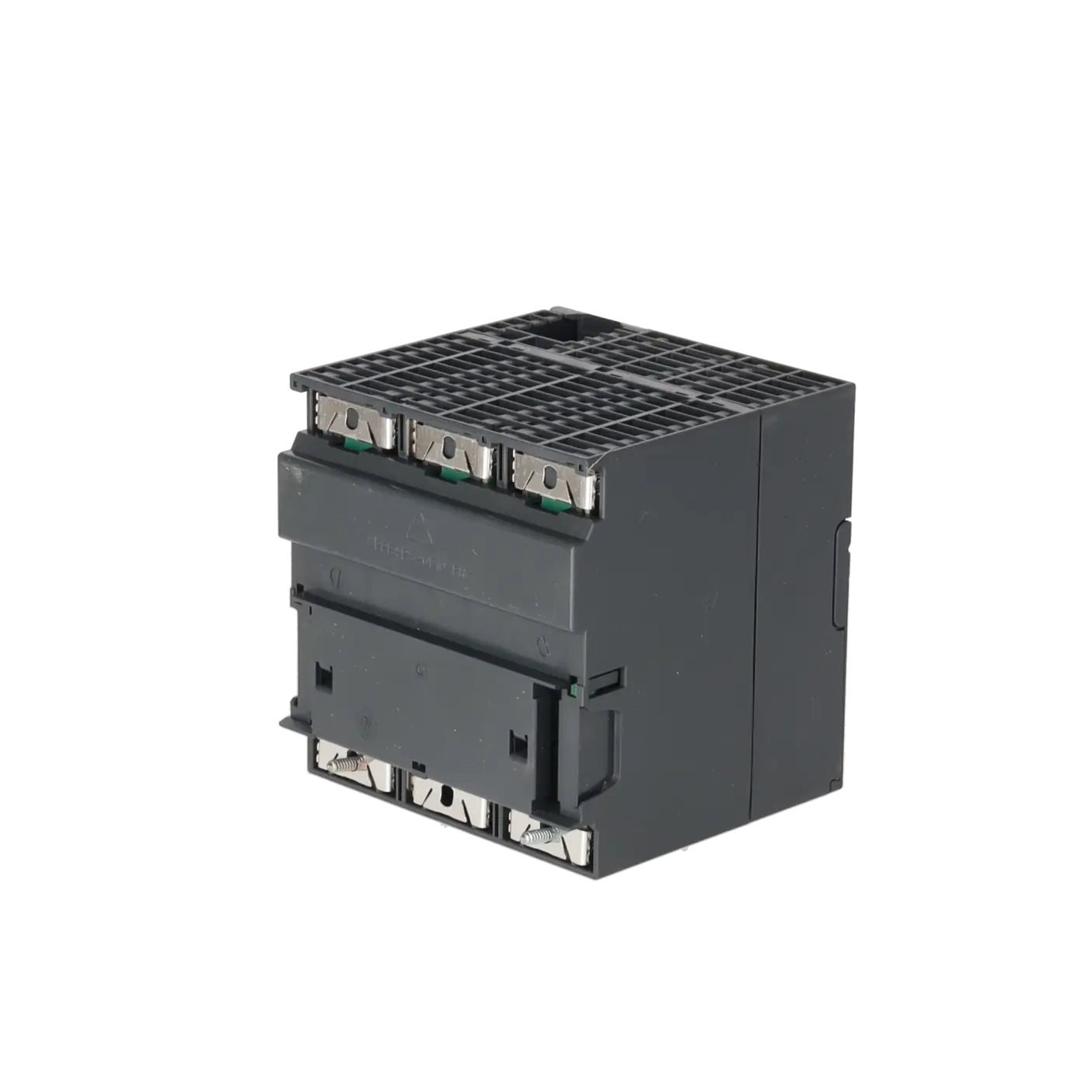
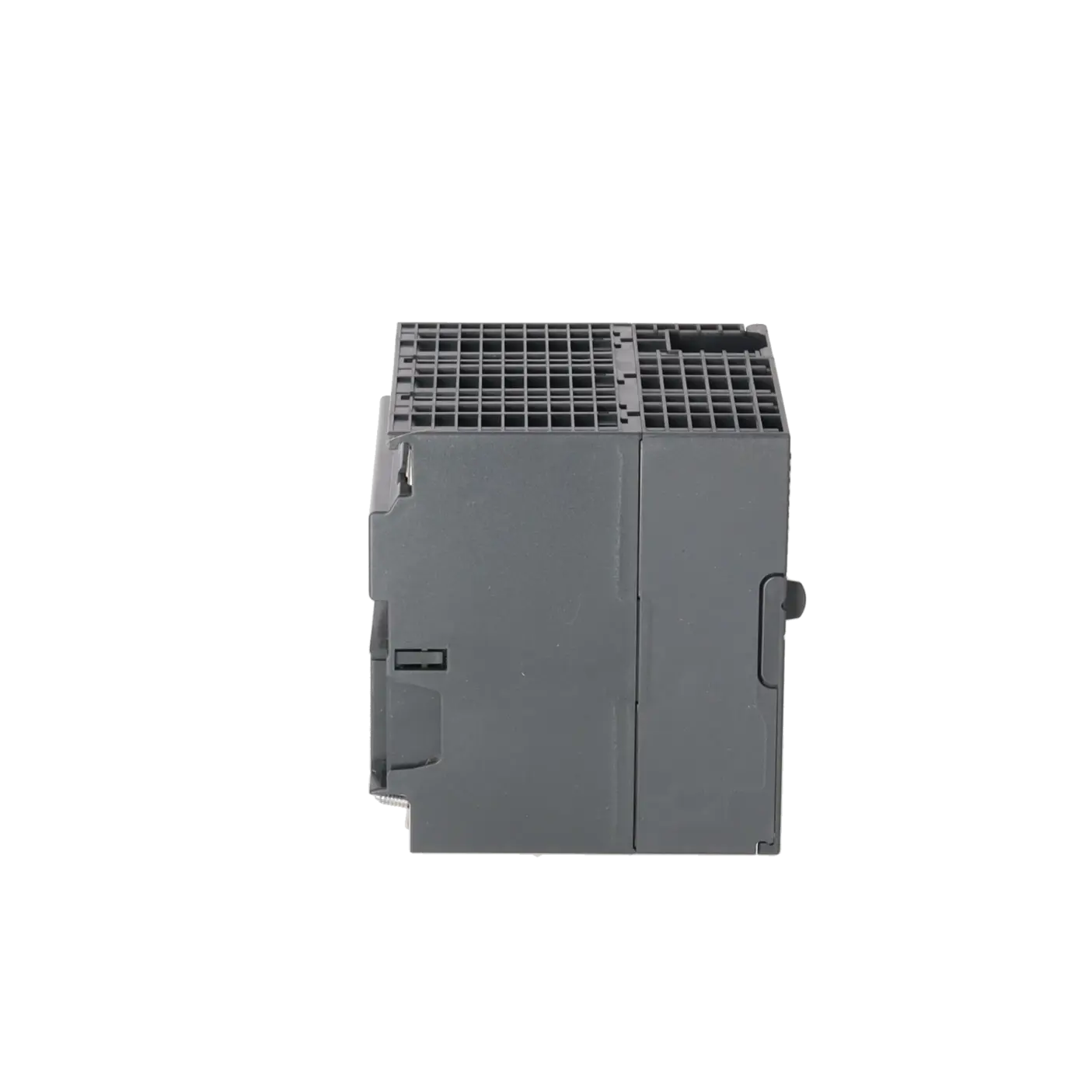
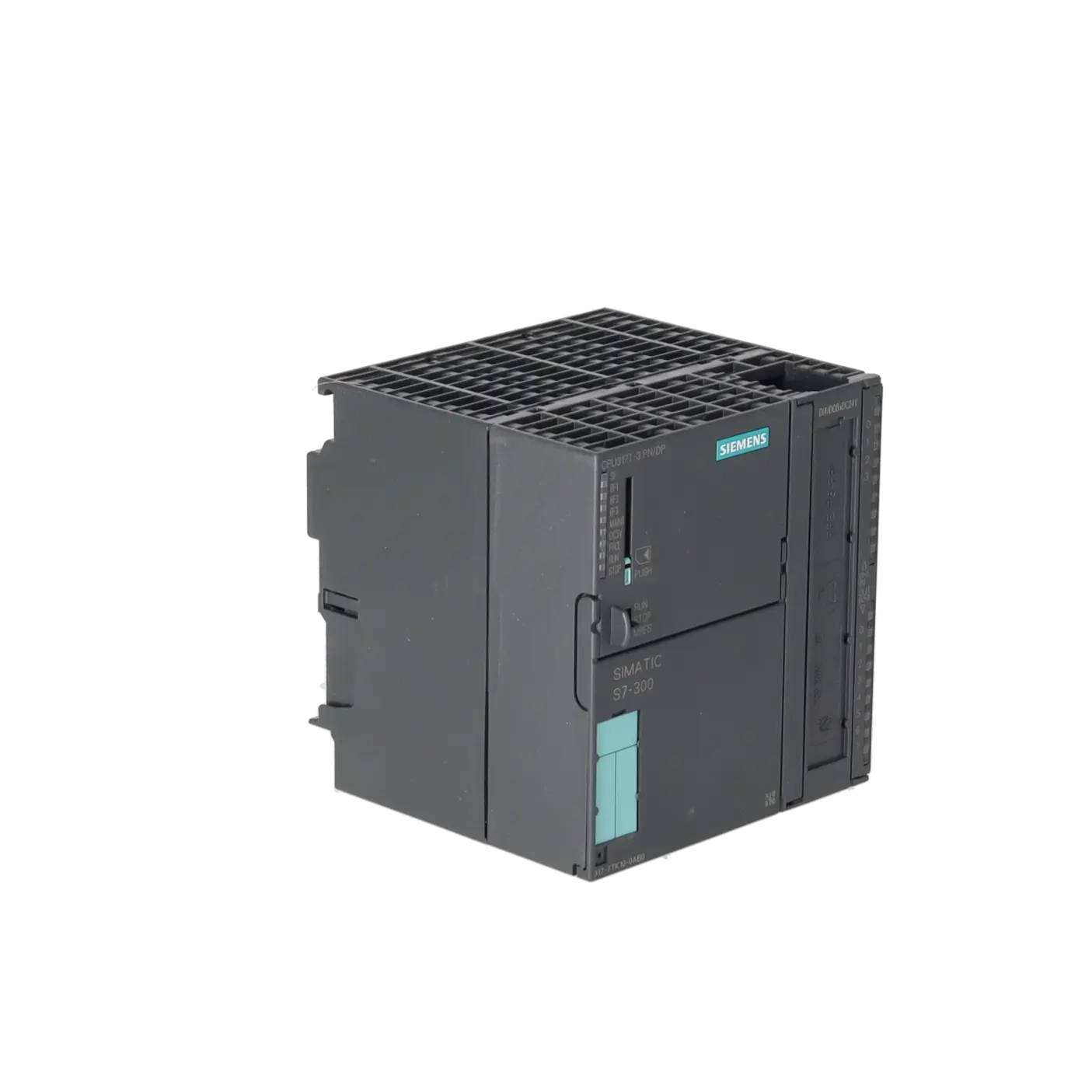
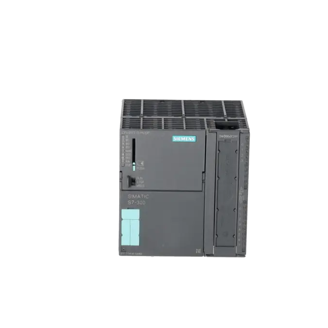
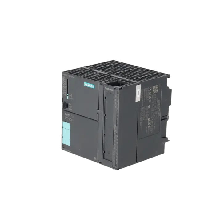
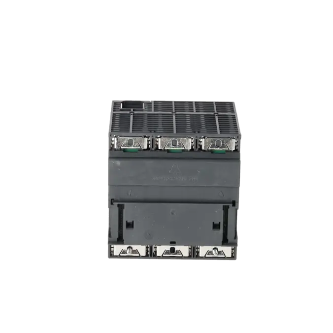
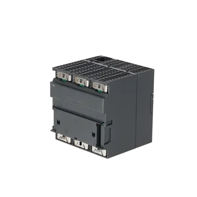
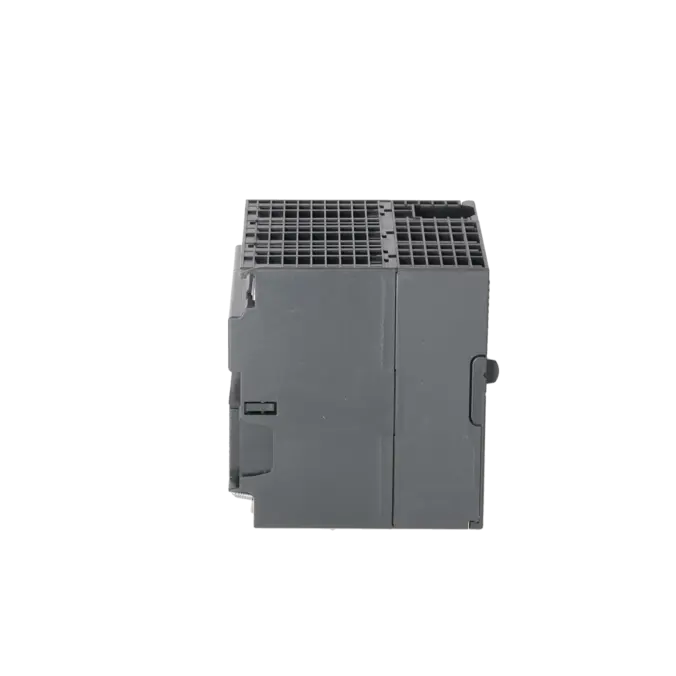
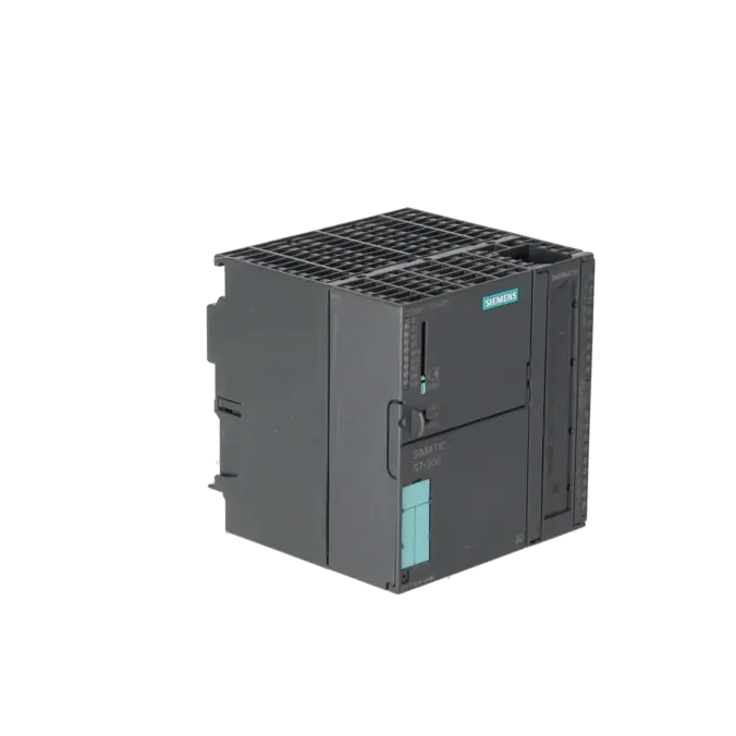
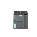
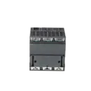
SIMATIC S7-300, CPU 317T-3 PN/DP, CENTRAL PROCESSING UNIT FOR PLC AND TECHNOLOGY TASKS, 1024 KB WORK MEMORY, 1ST INTERFACE MPI/DP 12 MBIT/S, 2ND INTERFACE DP (DRIVE), 3RD INTERFACE ETHERNET PROFINET WITH 2-PORT SWITCH, INTEGR. I/O FOR TECHNOLOGY, FRONT CO
Services for SIEMENS 6ES7317-7TK10-0AB0
Repair
from 2.237,66 €
to 3.614,69 €
Replacement
Used
6.635,77 €
4.976,83 €
New
8.606,40 €
6.454,80 €
SIEMENS |
6ES7317-7TK10-0AB0 –
additional product information
| Delivery information | |||
|---|---|---|---|
| Export identifier | AL: N ECCN: EAR99H | ||
| Net weight | 0.713 | ||
| Quantity | 1 Stück | ||
| Packaging quantity | 1 | ||
| Additional product information | |||
|---|---|---|---|
| Product status | |||
| EAN | 4025515082545 | ||
| UPC | 887621409296 | ||
| Static lot number | 85371091 | ||
| List indicator | ST73 | ||
| Product group | 4256 | ||
| Country of origin | DE | ||
| Compliance with the substance restrictions according to RoHS directive | Since: 20130528 | ||
| Product classifications | Version | Classification | |
|---|---|---|---|
| eClass | 4 | / | |
| eClass | 5.1 | 27-24-22-07 | |
| eClass | 6.0 | 27-24-22-07 | |
| ETIM | 3 | / | |
| ETIM | 4 | EC000236 | |
| ETIM | 5 | EC000236 | |
What is 6ES7317-7TK10-0AB0 and where is it used?
The 6ES7317-7TK10-0AB0 is a SIMATIC S7-300 Technology CPU 317T-3 PN/DP from Siemens. It is designed for both traditional PLC tasks and technology-oriented motion control applications. These include machines with positioning, synchronised motion, electronic cam, or drive control functions. The assembly combines 1,024 KB of work memory, an MPI/DP interface, a DP(DRIVE) interface, and PROFINET with an integrated 2-port switch. In addition, it features integrated technology I/O with 4 digital inputs and 8 digital outputs. This makes the CPU particularly suitable for packaging machinery, handling systems, conveyor technology, and axis control applications, where standard control and advanced technology functions are to be combined within a single compact central processing assembly.
Overview of the key technical data and what they mean
For maintenance and procurement purposes, the following specifications are particularly important. The CPU operates on 24 V DC within a permissible voltage range of 19.2 to 28.8 V DC, requires a typical current consumption of 1,050 mA, and has a typical power dissipation of 7.5 W. The 1,024 KB work memory is designed for demanding user programs and technology objects. The load memory is stored on a removable SIMATIC Micro Memory Card (MMC), with a minimum capacity of 8 MB required. With 8 KB of input address space, 8 KB of output address space, isochronous operation via PROFIBUS DP or PROFINET, and integrated digital technology I/O, the CPU is optimised for fast and time-critical machine functions. For purchasing departments, it is important to note that the article number refers to a complete central processing assembly, not merely a communication or expansion module.
Product status, life cycle status and obsolescence
Siemens officially lists the 6ES7317-7TK10-0AB0 as a spare part. Within the Siemens SIMATIC S7-300 and ET 200M product families, the lifecycle milestone PM400 has already been reached, while PM410 (Product Cancellation) became effective on 01 October 2025. For operators, this means that the assembly remains technically relevant, but procurement risks relating to availability, price volatility, and spare parts supply are increasing. No direct 1:1 plug-compatible successor for this exact order number could be clearly identified in the available sources. However, Siemens describes the 31xT-3 PN/DP series as a spare-part-compatible successor to the older 31xT-2 DP generation. For modernisation projects rather than direct replacement, Siemens provides migration paths towards the S7-1500 and S7-1500T platforms.
Available EICHLER services and why they are relevant
For operators of ageing S7-300 technology systems, the most relevant options are repair, exchange, used-unit procurement, and new-unit procurement. In the EICHLER shop, a repair service is offered for this assembly with a typical turnaround time of 2 to 5 days. The service includes technical cleaning, preventive maintenance, comprehensive functional testing, and a minimum 24-month warranty. In addition, exchange solutions on request, used assemblies, and new assemblies are available. For maintenance personnel, this is important because unexpected downtime can often be bridged more quickly through repair or exchange than by relying solely on the procurement of new parts. For purchasing departments, these options provide greater flexibility in terms of price, delivery time, and the remaining service life of the installation. For decision-makers, the key benefit is that operational reliability can still be maintained during the obsolescence phase through well-planned repair and exchange strategies.
| Attribute | Value |
|---|---|
| General information | |
| Product type designation | CPU 317T-3 PN/DP |
| HW functional status | 1 |
| Firmware version | CPU: V3.2; integrated technology V4.1.5 |
| Product function | |
| ● Isochronous mode | Yes; Via PROFIBUS DP or PROFINET interface |
| Engineering with | |
| ● Programming package | STEP 7 V5.5 SP2 or higher and S7-Technology option package V4.2 SP3 |
| Supply voltage | |
| Rated value (DC) | 24 V |
| permissible range, lower limit (DC) | 19.2 V |
| permissible range, upper limit (DC) | 28.8 V |
| external protection for power supply lines (recommendation) | 2 A min. |
| Load voltage L+ | |
| ● Rated value (DC) | 24 V |
| ● Reverse polarity protection | Yes |
| Digital outputs | |
| — Rated value (DC) | 24 V; 2L+ |
| — Reverse polarity protection | No; 2L+ |
| Input current | |
| Current consumption (rated value) | 1 050 mA |
| Current consumption (in no-load operation), typ. | 230 mA |
| Inrush current, typ. | 6.5 A |
| I²t | 1 A²·s |
| Power loss | |
| Power loss, typ. | 7.5 W |
| Memory | |
| Work memory | |
| ● integrated | 1 024 kbyte |
| ● expandable | No |
| Load memory | |
| ● Plug-in (MMC) | Yes |
| ● Plug-in (MMC), max. | 8 Mbyte |
| ● Data management on MMC (after last programming), min. | 10 a |
| Backup | |
| ● present | Yes; Guaranteed by MMC (maintenance-free) |
| ● without battery | Yes; Program and data |
| CPU processing times | |
| for bit operations, typ. | 0.025 µs |
| for word operations, typ. | 0.03 µs |
| for fixed point arithmetic, typ. | 0.04 µs |
| for floating point arithmetic, typ. | 0.16 µs |
| CPU-blocks | |
| Number of blocks (total) | 2 048; (DBs, FCs, FBs); the maximum number of loadable blocks can be reduced by the MMC used. |
| DB | |
| ● Number, max. | 2 048; Number range: 1 to 16000 |
| ● Size, max. | 64 kbyte |
| FB | |
| ● Number, max. | 2 048; Number range: 0 to 7999 |
| ● Size, max. | 64 kbyte |
| FC | |
| ● Number, max. | 2 048; Number range: 0 to 7999 |
| ● Size, max. | 64 kbyte |
| OB | |
| ● Number, max. | see instruction list |
| ● Size, max. | 64 kbyte |
| ● Number of free cycle OBs | 1; OB 1 |
| ● Number of time alarm OBs | 1; OB 10 |
| ● Number of delay alarm OBs | 2; OB 20, 21 |
| ● Number of cyclic interrupt OBs | 4; OB 32, 33, 34, 35 |
| ● Number of process alarm OBs | 1; OB 40 |
| ● Number of DPV1 alarm OBs | 3; OB 55, 56, 57 |
| ● Number of isochronous mode OBs | 1; OB 61 - isochronous mode is possible either on DP or PROFINET IO (not simultaneously) |
| ● Number of technology synchronous alarm OBs | 1; OB 65 |
| ● Number of startup OBs | 1; OB 100 |
| ● Number of asynchronous error OBs | 6; OB 80, 82, 83, 85, 86, 87 (OB83 only for PROFINET IO) |
| ● Number of synchronous error OBs | 2; OB 121, 122 |
| Nesting depth | |
| ● per priority class | 16 |
| ● additional within an error OB | 4 |
| Counters, timers and their retentivity | |
| S7 counter | |
| ● Number | 512 |
| Retentivity | |
| — adjustable | Yes |
| — preset | Z 0 to Z 7 |
| Counting range | |
| — adjustable | Yes |
| — lower limit | 0 |
| — upper limit | 999 |
| IEC counter | |
| ● present | Yes |
| ● Type | SFB |
| ● Number | Unlimited (limited only by RAM capacity) |
| S7 times | |
| ● Number | 512 |
| Retentivity | |
| — adjustable | Yes |
| — preset | No retentivity |
| Time range | |
| — lower limit | 10 ms |
| — upper limit | 9 990 s |
| IEC timer | |
| ● present | Yes |
| ● Type | SFB |
| ● Number | Unlimited (limited only by RAM capacity) |
| Data areas and their retentivity | |
| Retentive data area (incl. timers, counters, flags), max. | 256 kbyte |
| Flag | |
| ● Size, max. | 4 096 byte |
| ● Retentivity available | Yes; From MB 0 to MB 4 095 |
| ● Retentivity preset | MB 0 to MB 15 |
| ● Number of clock memories | 8; 1 memory byte |
| Data blocks | |
| ● Retentivity adjustable | Yes; via non-retain property on DB |
| ● Retentivity preset | Yes |
| Local data | |
| ● per priority class, max. | 32 768 byte; Max. 2048 bytes per block |
| Address area | |
| I/O address area | |
| ● Inputs | 8 192 byte |
| ● Outputs | 8 192 byte |
| of which distributed | |
| — Inputs | 8 192 byte |
| — Outputs | 8 192 byte |
| Process image | |
| ● Inputs | 8 192 byte |
| ● Outputs | 8 192 byte |
| ● Inputs, adjustable | 8 192 byte |
| ● Outputs, adjustable | 8 192 byte |
| ● Inputs, default | 256 byte |
| ● Outputs, default | 256 byte |
| Subprocess images | |
| ● Number of subprocess images, max. | 1; With PROFINET IO, the length of the user data is limited to 1600 bytes |
| Digital channels | |
| ● Inputs | 65 536 |
| — of which central | 256 |
| ● Outputs | 65 536 |
| — of which central | 256 |
| Analog channels | |
| ● Inputs | 4 096 |
| — of which central | 64 |
| ● Outputs | 4 096 |
| — of which central | 64 |
| Hardware configuration | |
| Number of expansion units, max. | 0 |
| Number of DP masters | |
| ● integrated | 2; 1 DP and 1 DP (drive) |
| ● via CP | 2; for DP |
| Number of operable FMs and CPs (recommended) | |
| ● FM | 8 |
| ● CP, PtP | 8 |
| ● CP, LAN | 8 |
| Rack | |
| ● Racks, max. | 1 |
| ● Modules per rack, max. | 8 |
| Time of day | |
| Clock | |
| ● Hardware clock (real-time) | Yes |
| ● retentive and synchronizable | Yes |
| ● Backup time | 6 wk; At 40 °C ambient temperature |
| ● Deviation per day, max. | 10 s; Typ.: 2 s |
| ● Behavior of the clock following POWER-ON | Clock continues running after POWER OFF |
| ● Behavior of the clock following expiry of backup period | the clock continues at the time of day it had when power was switched off |
| Operating hours counter | |
| ● Number | 4 |
| ● Number/Number range | 0 to 3 |
| ● Range of values | 0 to 2^31 hours (when using SFC 101) |
| ● Granularity | 1 h |
| ● retentive | Yes; Must be restarted at each restart |
| Clock synchronization | |
| ● supported | Yes |
| ● to MPI, master | Yes |
| ● on MPI, device | Yes |
| ● to DP, master | Yes |
| ● on DP, device | Yes; Only time-of-day slave |
| ● in AS, master | Yes |
| ● in AS, device | Yes |
| ● on Ethernet via NTP | Yes; As client |
| Digital inputs | |
| Number of digital inputs | 4 |
| ● of which inputs usable for technological functions | 4 |
| Input characteristic curve in accordance with IEC 61131, type 1 | Yes |
| Number of simultaneously controllable inputs | |
| horizontal installation | |
| — up to 40 °C, max. | 4 |
| — up to 60 °C, max. | 4 |
| vertical installation | |
| — up to 40 °C, max. | 4 |
| Input voltage | |
| ● Rated value (DC) | 24 V |
| ● for signal "0" | -3 to +5V |
| ● for signal "1" | +15 to +30 V |
| Input current | |
| ● for signal "1", typ. | 7 mA |
| Input delay (for rated value of input voltage) | |
| for technological functions | |
| — at "0" to "1", max. | 10 µs; Typical |
| — at "1" to "0", max. | 10 µs; Typical |
| Cable length | |
| ● shielded, max. | 1 000 m |
| Digital outputs | |
| Number of digital outputs | 8 |
| ● of which high-speed outputs | 8 |
| Functions | for technology functions, e.g. high-speed cam switch signals |
| Short-circuit protection | Yes |
| ● Response threshold, typ. | 1 A |
| Limitation of inductive shutdown voltage to | 48 V |
| Controlling a digital input | No |
| Switching capacity of the outputs | |
| ● on lamp load, max. | 5 W |
| Load resistance range | |
| ● lower limit | 48 Ω |
| ● upper limit | 4 kΩ |
| Output voltage | |
| ● for signal "0", max. | 3 V; (2L+) |
| ● for signal "1", min. | Rated voltage -2.5 V |
| Output current | |
| ● for signal "1" rated value | 0.5 A |
| ● for signal "1" permissible range for 0 to 60 °C, min. | 5 mA |
| ● for signal "1" permissible range for 0 to 60 °C, max. | 0.6 A |
| ● for signal "0" residual current, max. | 0.3 mA |
| Parallel switching of two outputs | |
| ● for uprating | No |
| ● for redundant control of a load | No |
| Switching frequency | |
| ● with resistive load, max. | 100 Hz |
| ● with inductive load, max. | 0.2 Hz; According to IEC 60947-5-1, DC-13 |
| ● on lamp load, max. | 100 Hz |
| Total current of the outputs (per group) | |
| horizontal installation | |
| — up to 40 °C, max. | 4 A |
| — up to 60 °C, max. | 3 A |
| all other mounting positions | |
| — up to 40 °C, max. | 4 A |
| Integrated high-speed cams | |
| ● Switching accuracy (+/-) | 70 µs |
| Cable length | |
| ● shielded, max. | 1 000 m |
| Analog inputs | |
| Number of analog inputs | 0 |
| Encoder | |
| Connectable encoders | |
| ● 2-wire sensor | No |
| Interfaces | |
| Number of PROFINET interfaces | 1 |
| Number of RS 485 interfaces | 2 |
| Number of RS 422 interfaces | 0 |
| 1. Interface | |
| Interface type | Integrated RS 485 interface |
| Isolated | Yes |
| Interface types | |
| ● RS 485 | Yes |
| ● Output current of the interface, max. | 200 mA |
| Protocols | |
| ● MPI | Yes |
| ● PROFIBUS DP master | Yes |
| ● PROFIBUS DP device | Yes |
| ● Point-to-point connection | No |
| MPI | |
| ● Transmission rate, max. | 12 Mbit/s |
| Services | |
| — PG/OP communication | Yes |
| — Routing | Yes |
| — Global data communication | Yes |
| — S7 basic communication | Yes |
| — S7 communication | Yes |
| — S7 communication, as client | No; but via CP and loadable FB |
| — S7 communication, as server | Yes |
| PROFIBUS DP master | |
| ● Transmission rate, max. | 12 Mbit/s |
| ● max. number of DP devices | 124 |
| Services | |
| — PG/OP communication | Yes |
| — Routing | Yes |
| — Global data communication | No |
| — S7 basic communication | Yes; I blocks only |
| — S7 communication | Yes |
| — S7 communication, as client | No |
| — S7 communication, as server | Yes |
| — Equidistance | Yes |
| — Isochronous mode | Yes; OB 61; isochronous mode can only be used alternatively on PROFIBUS DP or PROFINET IO |
| — SYNC/FREEZE | Yes |
| — activation/deactivation of DP devices | Yes |
| — max. number of DP devices that can be activated/deactivated at the same time | 8 |
| — Direct data exchange (slave-to-slave communication) | Yes; as subscriber |
| — DPV1 | Yes |
| Address area | |
| — Inputs, max. | 8 kbyte |
| — Outputs, max. | 8 kbyte |
| User data per DP device | |
| — Inputs, max. | 244 byte |
| — Outputs, max. | 244 byte |
| PROFIBUS DP device | |
| ● Transmission rate, max. | 12 Mbit/s |
| ● automatic baud rate search | Yes; only with passive interface |
| ● Address area, max. | 32 |
| ● User data per address area, max. | 32 byte |
| Services | |
| — PG/OP communication | Yes |
| — Routing | Yes; Only with active interface |
| — Global data communication | No |
| — S7 basic communication | No |
| — S7 communication | Yes |
| — S7 communication, as client | No |
| — S7 communication, as server | Yes; Connection configured on one side only |
| — Direct data exchange (slave-to-slave communication) | Yes |
| — DPV1 | No |
| Transfer memory | |
| — Inputs | 244 byte |
| — Outputs | 244 byte |
| 2. Interface | |
| Interface type | Integrated RS 485 interface |
| Isolated | Yes |
| Interface types | |
| ● RS 485 | Yes |
| ● Output current of the interface, max. | 200 mA |
| Protocols | |
| ● MPI | No |
| ● PROFIBUS DP master | Yes; DP(DRIVE)-Master |
| ● PROFIBUS DP device | No |
| ● Point-to-point connection | No |
| PROFIBUS DP master | |
| ● Transmission rate, max. | 12 Mbit/s |
| ● max. number of DP devices | 64 |
| Services | |
| — PG/OP communication | No |
| — Routing | No |
| — Global data communication | No |
| — S7 basic communication | No |
| — S7 communication | No |
| — Equidistance | Yes |
| — Isochronous mode | Yes |
| — SYNC/FREEZE | No |
| — activation/deactivation of DP devices | Yes |
| — DPV1 | No |
| Address area | |
| — Inputs, max. | 1 024 byte |
| — Outputs, max. | 1 024 byte |
| User data per DP device | |
| — Inputs, max. | 244 byte |
| — Outputs, max. | 244 byte |
| PROFIBUS DP device | |
| ● GSD file | http://support.automation.siemens.com in Product Support area |
| ● Transmission rate, max. | 12 Mbit/s |
| 3. Interface | |
| Interface type | PROFINET |
| Isolated | Yes |
| automatic detection of transmission rate | Yes; 10/100 Mbit/s |
| Autonegotiation | Yes |
| Autocrossing | Yes |
| Change of IP address at runtime, supported | Yes |
| Interface types | |
| ● RJ 45 (Ethernet) | Yes |
| ● Number of ports | 2 |
| ● integrated switch | Yes |
| Protocols | |
| ● MPI | No |
| ● PROFINET IO Controller | Yes; Also simultaneously with IO-Device functionality |
| ● PROFINET IO Device | Yes; Also simultaneously with IO Controller functionality |
| ● PROFIBUS DP master | No |
| ● PROFIBUS DP device | No |
| ● Open IE communication | Yes; Via TCP/IP, ISO on TCP, and UDP |
| ● Web server | Yes |
| ● Media redundancy | Yes |
| PROFINET IO Controller | |
| ● Transmission rate, max. | 100 Mbit/s |
| Services | |
| — PG/OP communication | Yes |
| — Routing | Yes |
| — S7 communication | Yes; with loadable FBs, max. configurable connections: 16, max. number of instances: 32 |
| — Isochronous mode | Yes; OB 61; isochronous mode can only be used alternatively on PROFIBUS DP or PROFINET IO |
| — Shared device | Yes |
| — Prioritized startup | Yes |
| — Number of IO devices with prioritized startup, max. | 32 |
| — Number of connectable IO Devices, max. | 128 |
| — Of which IO devices with IRT, max. | 64 |
| — of which in line, max. | 64 |
| — Number of connectable IO Devices for RT, max. | 128 |
| — of which in line, max. | 128 |
| — Activation/deactivation of IO Devices | Yes |
| — Number of IO Devices that can be simultaneously activated/deactivated, max. | 8 |
| — IO Devices changing during operation (partner ports), supported | Yes |
| — Number of IO Devices per tool, max. | 8 |
| — Device replacement without swap medium | Yes |
| — Send cycles | 250 µs, 500 µs, 1 ms, 2 ms, 4 ms |
| — Updating time | 250 µs to 512 ms (depending on the operating mode, see Manual "S7-300 CPU 31xC and CPU 31x, technical Data" for more details) |
| Address area | |
| — Inputs, max. | 8 kbyte |
| — Outputs, max. | 8 kbyte |
| — User data consistency, max. | 1 024 byte |
| PROFINET IO Device | |
| Services | |
| — PG/OP communication | Yes |
| — Routing | Yes |
| — S7 communication | Yes; with loadable FBs, max. configurable connections: 16, max. number of instances: 32 |
| — Isochronous mode | No |
| — IRT | Yes |
| — PROFIenergy | Yes; With SFB 73 / 74 prepared for loadable PROFIenergy standard FB for I-Device |
| — Shared device | Yes |
| — Number of IO Controllers with shared device, max. | 2 |
| Transfer memory | |
| — Inputs, max. | 1 440 byte; Per IO Controller with shared device |
| — Outputs, max. | 1 440 byte; Per IO Controller with shared device |
| Submodules | |
| — Number, max. | 64 |
| — User data per submodule, max. | 1 024 byte |
| Open IE communication | |
| ● Number of connections, max. | 16 |
| ● Local port numbers used at the system end | 0, 20, 21, 23, 25, 80, 102, 135, 161, 443, 8080, 34962, 34963, 34964, 65532, 65533, 65534, 65535 |
| ● Keep-alive function, supported | Yes |
| Protocols | |
| PROFIsafe | No |
| Redundancy mode | |
| Media redundancy | |
| — Switchover time on line break, typ. | 200 ms; PROFINET MRP |
| — Number of stations in the ring, max. | 50 |
| Open IE communication | |
| ● TCP/IP | Yes; via integrated PROFINET interface and loadable FBs |
| — Number of connections, max. | 16 |
| — Data length for connection type 01H, max. | 1 460 byte |
| — Data length for connection type 11H, max. | 32 768 byte |
| — several passive connections per port, supported | Yes |
| ● ISO-on-TCP (RFC1006) | Yes; via integrated PROFINET interface and loadable FBs |
| — Number of connections, max. | 16 |
| — Data length, max. | 32 768 byte |
| ● UDP | Yes; via integrated PROFINET interface and loadable FBs |
| — Number of connections, max. | 16 |
| — Data length, max. | 1 472 byte |
| Web server | |
| ● supported | Yes |
| ● User-defined websites | Yes |
| ● Number of HTTP clients | 5 |
| Communication functions | |
| PG/OP communication | Yes |
| Data record routing | Yes |
| Global data communication | |
| ● supported | Yes |
| ● Number of GD loops, max. | 8 |
| ● Number of GD packets, max. | 8 |
| ● Number of GD packets, transmitter, max. | 8 |
| ● Number of GD packets, receiver, max. | 8 |
| ● Size of GD packets, max. | 22 byte |
| ● Size of GD packet (of which consistent), max. | 22 byte |
| S7 basic communication | |
| ● supported | Yes |
| ● User data per job, max. | 76 byte |
| ● User data per job (of which consistent), max. | 76 byte; 76 bytes (with X_SEND or X_RCV); 64 bytes (with X_PUT or X_GET as server) |
| S7 communication | |
| ● supported | Yes |
| ● as server | Yes |
| ● as client | Yes; via integrated PROFINET interface and loadable FB or via CP and loadable FB |
| ● User data per job, max. | See online help of STEP 7 (shared parameters of the SFBs/FBs and of the SFCs/FCs of S7 Communication) |
| S5 compatible communication | |
| ● supported | Yes; via CP and loadable FC |
| Number of connections | |
| ● overall | 32 |
| ● usable for PG communication | 31 |
| — reserved for PG communication | 1 |
| — adjustable for PG communication, min. | 1 |
| — adjustable for PG communication, max. | 31 |
| ● usable for OP communication | 31 |
| — reserved for OP communication | 1 |
| — adjustable for OP communication, min. | 1 |
| — adjustable for OP communication, max. | 31 |
| ● usable for S7 basic communication | 30 |
| — reserved for S7 basic communication | 0 |
| — adjustable for S7 basic communication, min. | 0 |
| — adjustable for S7 basic communication, max. | 30 |
| ● usable for S7 communication | 16 |
| — reserved for S7 communication | 0 |
| — adjustable for S7 communication, min. | 0 |
| — adjustable for S7 communication, max. | 16 |
| ● total number of instances, max. | 32 |
| ● usable for routing | X1 as MPI: max. 10; X1 as DP master: max. 24; X1 as DP slave (active): max. 14; X2 as PROFINET: 24 max. |
| S7 message functions | |
| Number of login stations for message functions, max. | 32; Depending on the configured connections for PG/OP and S7 basic communication |
| Process diagnostic messages | Yes |
| simultaneously active Alarm_S blocks, max. | 300 |
| Test commissioning functions | |
| Status block | Yes; Up to 2 simultaneously |
| Single step | Yes |
| Number of breakpoints | 4; without continuation |
| Status/control | |
| ● Status/control variable | Yes |
| ● Variables | Inputs, outputs, memory bits, DB, times, counters |
| ● Number of variables, max. | 30 |
| — of which status variables, max. | 30 |
| — of which control variables, max. | 14 |
| Forcing | |
| ● Forcing | Yes |
| ● Forcing, variables | Inputs, outputs |
| ● Number of variables, max. | 10 |
| Diagnostic buffer | |
| ● present | Yes |
| ● Number of entries, max. | 500 |
| — adjustable | No |
| — of which powerfail-proof | 100; Only the last 100 entries are retained |
| ● Number of entries readable in RUN, max. | 499 |
| — adjustable | Yes; From 10 to 499 |
| — preset | 10 |
| Service data | |
| ● can be read out | Yes |
| Interrupts/diagnostics/status information | |
| Alarms | No |
| Diagnostics function | No |
| Diagnostics indication LED | |
| ● Status indicator digital input (green) | Yes |
| ● Status indicator digital output (green) | Yes |
| Potential separation | |
| Potential separation digital inputs | |
| ● between the channels and backplane bus | Yes |
| Potential separation digital outputs | |
| ● between the channels and backplane bus | Yes |
| Isolation | |
| Isolation tested with | 500 V DC |
| Ambient conditions | |
| Ambient temperature during operation | |
| ● min. | 0 °C |
| ● max. | 60 °C |
| Configuration | |
| Configuration software | |
| ● STEP 7 | Yes; STEP 7 V5.5 SP2 or higher and S7-Technology option package V4.2 SP3 |
| Programming | |
| ● Command set | see instruction list |
| ● Nesting levels | 8 |
| ● System functions (SFC) | see instruction list |
| ● System function blocks (SFB) | see instruction list |
| Programming language | |
| — LAD | Yes |
| — FBD | Yes |
| — STL | Yes |
| — SCL | Yes |
| — CFC | Yes |
| — GRAPH | Yes |
| — HiGraph® | Yes |
| Know-how protection | |
| ● User program protection/password protection | Yes |
| ● Block encryption | Yes; With S7 block Privacy |
| Dimensions | |
| Width | 120 mm |
| Height | 125 mm |
| Depth | 130 mm |
| Weights | |
| Weight, approx. | 640 g |
| Fault description | Possible solution |
|---|---|
| Why is the SF LED flashing on the CPU 317T-3 PN/DP and the CPU requesting a memory reset? | If the STOP/SF indication changes to the pattern associated with a memory reset, the CPU is either requesting or already performing a memory reset. First check whether the installed Micro Memory Card (MMC) is functional and suitable for the CPU. Then read the diagnostic buffer and perform the memory reset according to the Siemens procedure. If the CPU requests another memory reset afterwards, the MMC should be reformatted or replaced for testing purposes. If the SF indication remains active after this, a defect in the assembly itself or in the firmware base is likely. |
| Why does the 6ES7317-7TK10-0AB0 switch to SF and no longer appear online after replacing or inserting an MMC? | A common cause is an unsuitable or incorrectly prepared MMC. With S7-300 CPUs, an incorrect hardware configuration stored on the card can trigger an SF fault. Therefore, check whether the card is intended for this CPU, erase or format the MMC using an appropriate programming device, and then download the correct hardware configuration and user program again. It is also important to note that this CPU requires a Micro Memory Card with a minimum capacity of 8 MB. |
| Why does the CPU remain in STOP and the SF LED stay illuminated after a hardware modification or the installation of an additional assembly? | In such cases, there is often a discrepancy between the configured hardware and the actual hardware installed. Typical causes include an incorrect hardware configuration, missing Hardware Support Packages (HSPs), or a configured module that does not exactly match the installed order number or firmware version. Compare the order numbers in the project with the actual CPU, update the hardware catalogue or HSP level, and download the complete hardware configuration again. The diagnostic buffer should then be checked before switching the CPU back to RUN. |
| Why does the CPU switch to STOP when a PROFIBUS/DP slave fails? | When a slave fails, the CPU may attempt to call diagnostic organisation blocks such as OB82, OB86, or OB122, depending on the type of access involved. If these OBs are not present, the CPU switches to STOP. For a robust system design, these OBs should exist, even if they initially contain no program code. The user program should then be enhanced to respond in a controlled manner to missing peripherals rather than continuing operation blindly. In addition, the bus terminations, node addresses, and power supplies of all DP devices should be checked to ensure stable operation. |
Which software is required for the 6ES7317-7TK10-0AB0?
For engineering the CPU 317T-3 PN/DP, you require at least STEP 7 V5.5 SP2 together with the S7-Technology V4.2 SP3 option package. For newer firmware versions, Siemens specifies STEP 7 V5.6 in combination with S7-Technology V4.2 SP5. This is important for purchasing and maintenance departments because procuring a CPU without a compatible engineering environment can lead to commissioning delays later on. Before ordering or replacing the CPU, it is therefore advisable to verify which STEP 7 and S7-Technology versions are actually available within your organisation.
Which memory card is required for the CPU 317T-3 PN/DP?
The assembly requires a SIMATIC Micro Memory Card (MMC), and Siemens specifies a minimum capacity of 8 MB. Without a suitable MMC, program loading, data backup, and reliable system operation cannot be properly ensured. In older S7-300 technology systems, the memory card is often an underestimated bottleneck because used CPUs are not always supplied with a suitable MMC. For service purposes, it is therefore recommended to treat the CPU and MMC as a functional pair and to keep at least one tested spare memory card in stock.
Is the 6ES7317-7TK10-0AB0 still a standard product or only a spare part?
Siemens classifies the 6ES7317-7TK10-0AB0 as a spare part. At the same time, the S7-300/ET 200M product family has already reached an advanced stage of its lifecycle: the product phase-out has been announced, and PM410 (Product Cancellation) became effective on 01 October 2025. In practical procurement terms, this means that new units may still be available, but long-term availability will increasingly depend on existing stock, specialised service providers, and verified used or exchange units.
Can I replace an older CPU 317T-2 DP with the 317T-3 PN/DP?
Siemens explicitly states in its documentation that the 31xT-3 PN/DP generation is a spare-part-compatible successor to the older 31xT-2 DP generation. This makes the 317T-3 PN/DP an obvious option when an older technology CPU needs to be replaced. Nevertheless, such a replacement is not purely a hardware issue. Before carrying out the exchange, the project configuration, firmware version, fieldbus structure, technology objects, and the available engineering software version should all be checked to ensure that the electrical replacement also results in a fully functional replacement.
Does the CPU support PROFINET diagnostics and device replacement without a removable storage medium?
Yes. Siemens specifies these PROFINET functions for the CPU 317T-3 PN/DP from firmware version V3.2 onwards. These include enhanced PROFINET diagnostic functions and support for device replacement without a removable storage medium. This is particularly useful for maintenance personnel because field devices can be replaced more quickly during service operations when the network topology, device names, and project configuration have been prepared correctly. For a smooth device replacement process, however, the firmware version, network configuration, and the actual network topology must all match.
What is the difference between the CPU 317T-3 PN/DP and the CPU 317TF-3 PN/DP?
The CPU 317TF-3 PN/DP is the variant with integrated safety functionality. Siemens explicitly describes it as a version with additional safety functions and a larger amount of work memory compared to the CPU 317T-3 PN/DP. The 317T-3 is the correct choice for standard technology and motion-control applications that do not require fail-safe functionality. The 317TF-3 becomes relevant when personnel protection or machine safety functions must also be implemented within the same controller. For purchasing departments, this distinction is important because the article number, software requirements, and application area are not interchangeable.