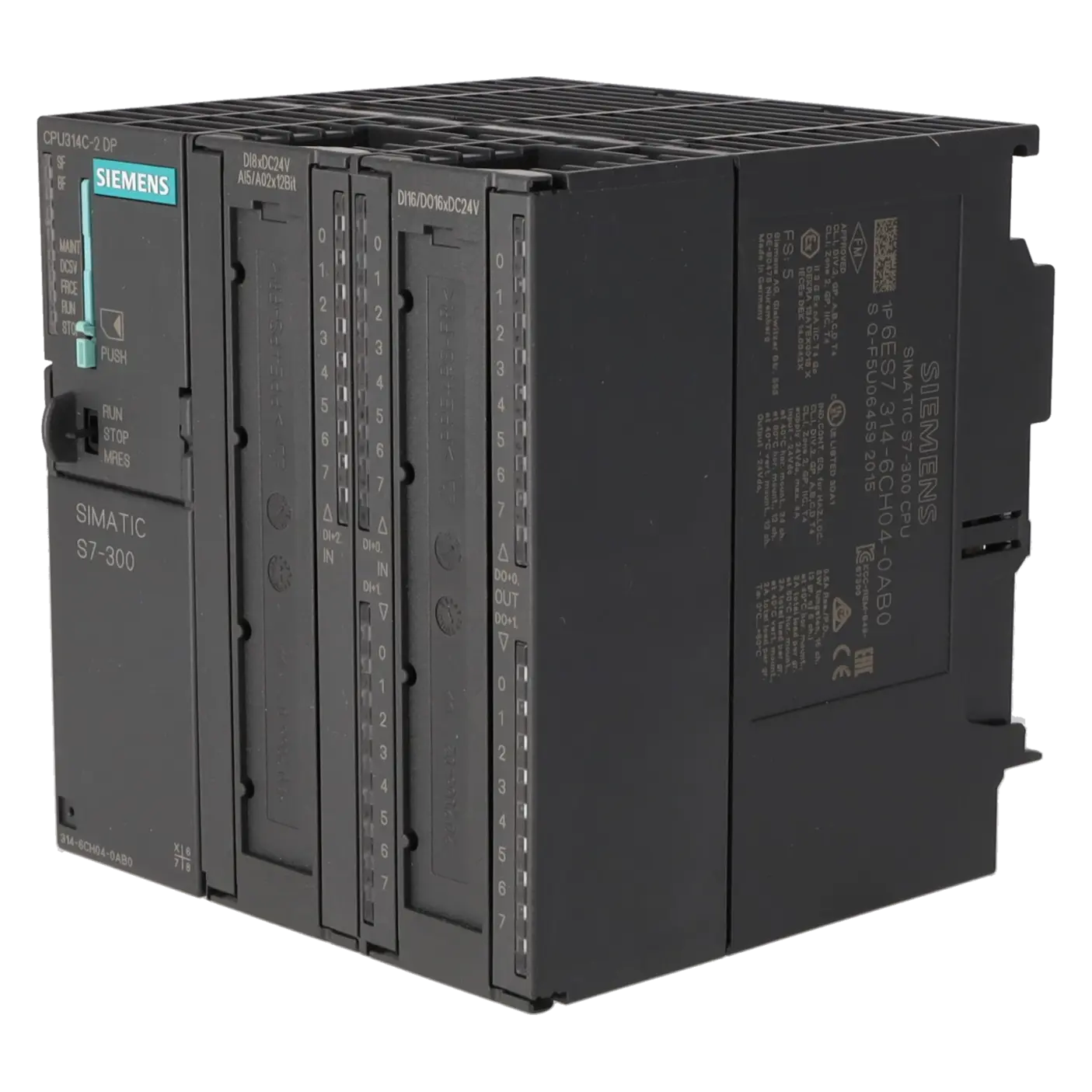
SIEMENS 6ES7314-6CH04-0AB0
-
SIEMENS | PLC Controls | Central Processing Units
- EICHLER-art.no.: K0252209
- EAN: 4025515079101
- UPC: 040892788600
Product description
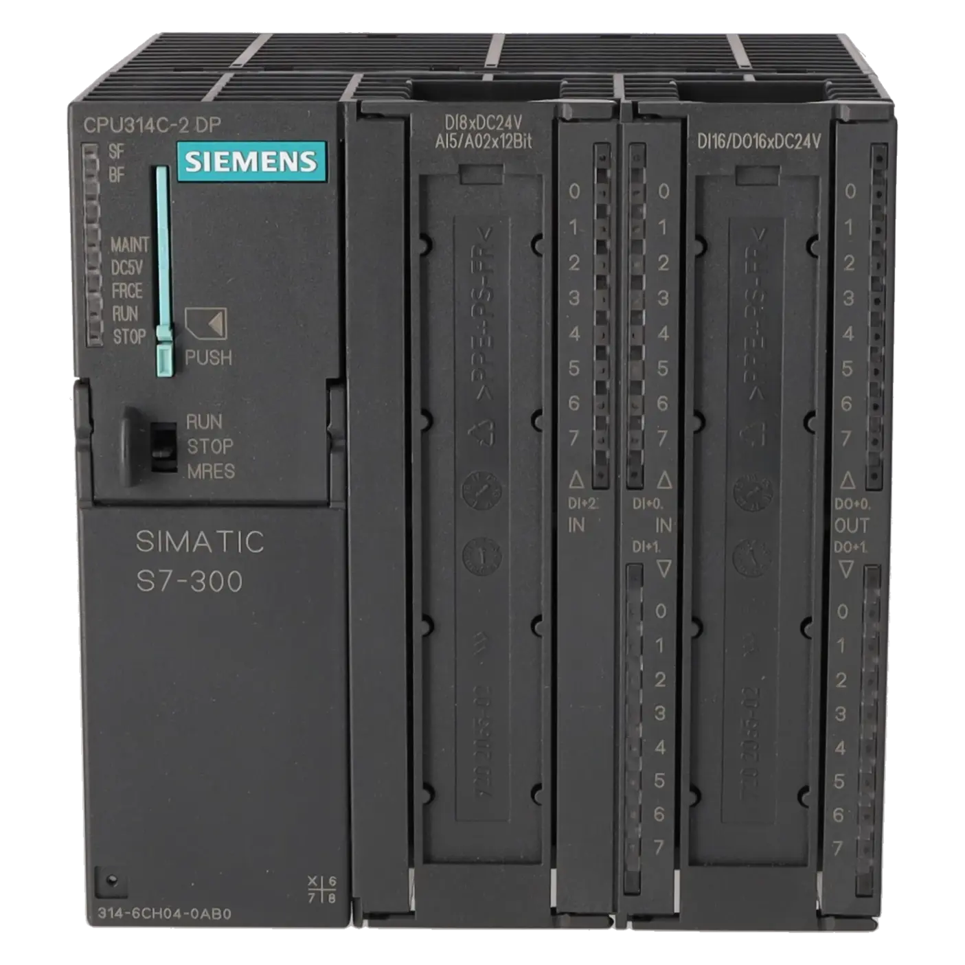
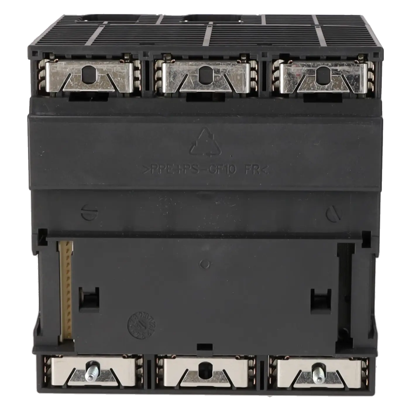
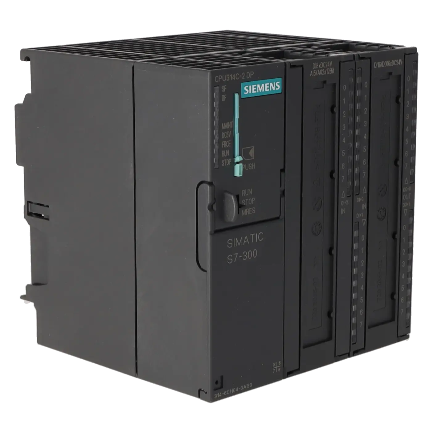
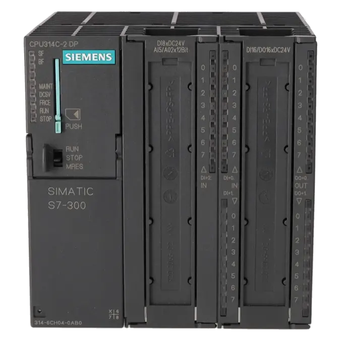
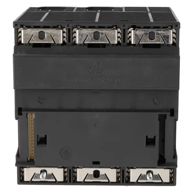
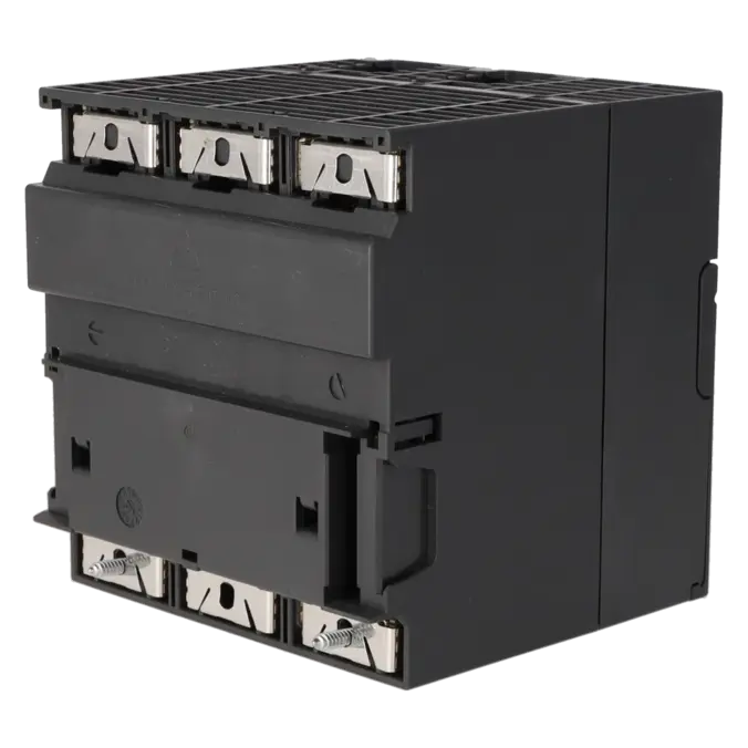
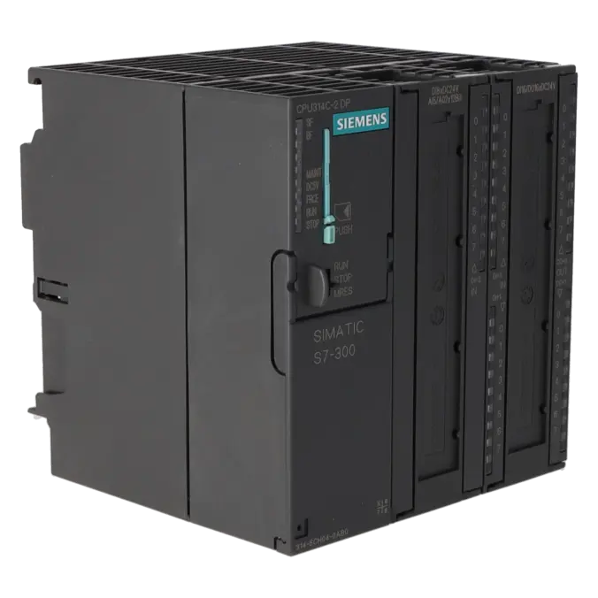
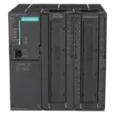
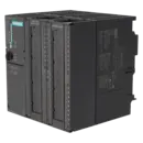
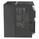
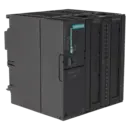
SIMATIC S7-300, CPU 314C-2 DP COMPACT CPU WITH MPI, 24 DI/16 DO, 4 AI, 2 AO, 1 PT100, 4 HIGH-SPEED COUNTERS (60 KHZ), INTEGRATED DP INTERFACE, INTEGR. POWER SUPPLY 24 V DC, WORK MEMORY 192 KB, FRONT CONNECTOR (2X 40-POLE) AND MICRO MEMORY CARD REQUIRED
Services for SIEMENS 6ES7314-6CH04-0AB0
Repair
from 964,19 €
to 1.735,53 €
Replacement
1.535,55 €
1.151,66 €
Used
2.153,67 €
1.615,25 €
New
3.092,10 €
2.319,07 €
SIEMENS |
6ES7314-6CH04-0AB0 –
additional product information
| Delivery information | |||
|---|---|---|---|
| Export identifier | AL: N ECCN: EAR99H | ||
| Net weight | 0.726 | ||
| Quantity | 1 Stück | ||
| Packaging quantity | 1 | ||
| Additional product information | |||
|---|---|---|---|
| Product status | |||
| EAN | 4025515079101 | ||
| UPC | 040892788600 | ||
| Static lot number | 85371091 | ||
| List indicator | ST73 | ||
| Product group | 4256 | ||
| Country of origin | DE | ||
| Compliance with the substance restrictions according to RoHS directive | Since: 20110913 | ||
| Product classifications | Version | Classification | |
|---|---|---|---|
| eClass | 4 | / | |
| eClass | 5.1 | 27-24-22-07 | |
| eClass | 6.0 | 27-24-22-07 | |
| ETIM | 3 | / | |
| ETIM | 4 | EC000236 | |
| ETIM | 5 | EC000236 | |
What is 6ES7314-6CH04-0AB0 and where is it used?
6ES7314-6CH04-0AB0 is a SIMATIC S7-300 CPU 314C-2 DP from Siemens. It is not just a standard PLC CPU, but a compact CPU with integrated inputs and outputs as well as an integrated PROFIBUS DP interface. This makes the assembly particularly suitable for machines and systems that require a central controller with directly connected signals and distributed I/O within a compact unit. Typical areas of application include serial production machines, special-purpose machinery, conveyor technology, packaging systems, testing equipment, and retrofit or legacy S7-300 installations. For maintenance personnel, it is attractive because it enables diagnostics, replacement and recommissioning within a familiar platform. For purchasing and production departments, it is relevant because it is a critical legacy assembly with a direct impact on system availability.
Overview of the key technical data and what it means
The CPU operates on 24 V DC and provides 24 digital inputs, 16 digital outputs, 4 analogue inputs, 2 analogue outputs, and 1 Pt100 input. In the market, this is often described as 5 analogue inputs, because the Pt100 channel is available in addition to the standard analogue inputs. The CPU also includes 4 high-speed counters up to 60 kHz, making it suitable for pulse, clock, frequency, and simple positioning applications. The 192 KB work memory is sufficient for many traditional S7-300 applications, while a SIMATIC Micro Memory Card (MMC) is required for operation and program storage. The integrated PROFIBUS DP interface allows operation as either a DP master or DP slave, enabling distributed I/O and field devices to be connected without the need for an additional communication assembly. For legacy systems, this combination of integrated I/O, PROFIBUS, and a compact design is often the decisive advantage.
Product status, life cycle status and obsolescence
Siemens currently lists 6ES7314-6CH04-0AB0 as a spare part. According to the manufacturer, the release for delivery was published on 20 May 2011, the Product phase-out announcement was issued on 01 October 2023, and Product cancellation / Type discontinuation became effective on 01 October 2025. For operators, this means that the CPU remains relevant in installed systems but is clearly within an advanced obsolescence and life cycle management phase. Siemens does not identify a plug-compatible new S7-300 successor as a direct 1:1 replacement in its product information. For migration projects, Siemens maps this CPU to the S7-1500 CPU 1512C, although this represents an engineering and migration path rather than a direct replacement without modifications. This distinction is particularly important when planning spare parts strategies, stockholding, and service partnerships.
Available EICHLER services and when they are relevant in practice
For 6ES7314-6CH04-0AB0, EICHLER offers several procurement and service options: Repair with a stated turnaround time of 2–5 days, Exchange within 1–3 days, as well as used and new units with available stock. EICHLER's repair service includes technical cleaning, preventive maintenance, comprehensive functional testing, and a minimum 24-month warranty. For maintenance personnel, repair is particularly useful when the existing assembly contains system-specific parameterisation and the installed hardware is intended to remain in service. Exchange is especially attractive when the cost of downtime exceeds the repair turnaround time. Used and new units help purchasing and production departments establish short-term availability or secure strategic stock levels. Particularly for discontinued S7-300 assemblies, these service options help maintain the operational reliability of legacy systems despite increasing obsolescence.
| Attribute | Value |
|---|---|
| General information | |
| Product type designation | CPU 314C-2 DP |
| HW functional status | 1 |
| Firmware version | V3.3 |
| Engineering with | |
| ● Programming package | STEP 7 V5.5 + SP1 or higher or STEP 7 V5.3 + SP2 or higher with HSP 203 |
| Supply voltage | |
| Rated value (DC) | 24 V |
| permissible range, lower limit (DC) | 19.2 V |
| permissible range, upper limit (DC) | 28.8 V |
| external protection for power supply lines (recommendation) | Miniature circuit breaker, type C; min. 2 A; miniature circuit breaker type B, min. 4 A |
| Mains buffering | |
| ● Mains/voltage failure stored energy time | 5 ms |
| ● Repeat rate, min. | 1 s |
| Load voltage L+ | |
| Digital inputs | |
| — Rated value (DC) | 24 V |
| — Reverse polarity protection | Yes |
| Digital outputs | |
| — Rated value (DC) | 24 V |
| — Reverse polarity protection | No |
| Input current | |
| Current consumption (rated value) | 880 mA |
| Current consumption (in no-load operation), typ. | 150 mA |
| Inrush current, typ. | 5 A |
| I²t | 0.7 A²·s |
| Digital inputs | |
| ● from load voltage L+ (without load), max. | 80 mA |
| Digital outputs | |
| ● from load voltage L+, max. | 50 mA |
| Power loss | |
| Power loss, typ. | 13 W |
| Memory | |
| Work memory | |
| ● integrated | 192 kbyte |
| ● expandable | No |
| Load memory | |
| ● Plug-in (MMC) | Yes |
| ● Plug-in (MMC), max. | 8 Mbyte |
| ● Data management on MMC (after last programming), min. | 10 a |
| Backup | |
| ● present | Yes; Guaranteed by MMC (maintenance-free) |
| ● without battery | Yes; Program and data |
| CPU processing times | |
| for bit operations, typ. | 0.06 µs |
| for word operations, typ. | 0.12 µs |
| for fixed point arithmetic, typ. | 0.16 µs |
| for floating point arithmetic, typ. | 0.59 µs |
| CPU-blocks | |
| Number of blocks (total) | 1 024; (DBs, FCs, FBs); the maximum number of loadable blocks can be reduced by the MMC used. |
| DB | |
| ● Number, max. | 1 024; Number range: 1 to 16000 |
| ● Size, max. | 64 kbyte |
| FB | |
| ● Number, max. | 1 024; Number range: 0 to 7999 |
| ● Size, max. | 64 kbyte |
| FC | |
| ● Number, max. | 1 024; Number range: 0 to 7999 |
| ● Size, max. | 64 kbyte |
| OB | |
| ● Number, max. | see instruction list |
| ● Size, max. | 64 kbyte |
| ● Number of free cycle OBs | 1; OB 1 |
| ● Number of time alarm OBs | 1; OB 10 |
| ● Number of delay alarm OBs | 2; OB 20, 21 |
| ● Number of cyclic interrupt OBs | 4; OB 32, 33, 34, 35 |
| ● Number of process alarm OBs | 1; OB 40 |
| ● Number of DPV1 alarm OBs | 3; OB 55, 56, 57 |
| ● Number of startup OBs | 1; OB 100 |
| ● Number of asynchronous error OBs | 5; OB 80, 82, 85, 86, 87 |
| ● Number of synchronous error OBs | 2; OB 121, 122 |
| Nesting depth | |
| ● per priority class | 16 |
| ● additional within an error OB | 4 |
| Counters, timers and their retentivity | |
| S7 counter | |
| ● Number | 256 |
| Retentivity | |
| — adjustable | Yes |
| — preset | Z 0 to Z 7 |
| Counting range | |
| — lower limit | 0 |
| — upper limit | 999 |
| IEC counter | |
| ● present | Yes |
| ● Type | SFB |
| ● Number | Unlimited (limited only by RAM capacity) |
| S7 times | |
| ● Number | 256 |
| Retentivity | |
| — adjustable | Yes |
| — preset | No retentivity |
| Time range | |
| — lower limit | 10 ms |
| — upper limit | 9 990 s |
| IEC timer | |
| ● present | Yes |
| ● Type | SFB |
| ● Number | Unlimited (limited only by RAM capacity) |
| Data areas and their retentivity | |
| Retentive data area (incl. timers, counters, flags), max. | 64 kbyte |
| Flag | |
| ● Size, max. | 256 byte |
| ● Retentivity available | Yes; MB 0 to MB 255 |
| ● Retentivity preset | MB 0 to MB 15 |
| ● Number of clock memories | 8; 1 memory byte |
| Data blocks | |
| ● Retentivity adjustable | Yes; via non-retain property on DB |
| ● Retentivity preset | Yes |
| Local data | |
| ● per priority class, max. | 32 kbyte; Max. 2048 bytes per block |
| Address area | |
| I/O address area | |
| ● Inputs | 2 048 byte |
| ● Outputs | 2 048 byte |
| of which distributed | |
| — Inputs | 2 003 byte |
| — Outputs | 2 010 byte |
| Process image | |
| ● Inputs | 2 048 byte |
| ● Outputs | 2 048 byte |
| ● Inputs, adjustable | 2 048 byte |
| ● Outputs, adjustable | 2 048 byte |
| ● Inputs, default | 128 byte |
| ● Outputs, default | 128 byte |
| Digital channels | |
| ● Inputs | 16 048 |
| — of which central | 1 016 |
| ● Outputs | 16 096 |
| — of which central | 1 008 |
| Analog channels | |
| ● Inputs | 1 006 |
| — of which central | 253 |
| ● Outputs | 1 007 |
| — of which central | 250 |
| Hardware configuration | |
| Number of expansion units, max. | 3 |
| Number of DP masters | |
| ● integrated | 1 |
| ● via CP | 4 |
| Number of operable FMs and CPs (recommended) | |
| ● FM | 8 |
| ● CP, PtP | 8 |
| ● CP, LAN | 10 |
| Rack | |
| ● Racks, max. | 4 |
| ● Modules per rack, max. | 8; In rack 3 max. 7 |
| Time of day | |
| Clock | |
| ● Hardware clock (real-time) | Yes |
| ● retentive and synchronizable | Yes |
| ● Backup time | 6 wk; At 40 °C ambient temperature |
| ● Deviation per day, max. | 10 s; Typ.: 2 s |
| ● Behavior of the clock following POWER-ON | Clock continues running after POWER OFF |
| ● Behavior of the clock following expiry of backup period | the clock continues at the time of day it had when power was switched off |
| Operating hours counter | |
| ● Number | 1 |
| ● Number/Number range | 0 |
| ● Range of values | 0 to 2^31 hours (when using SFC 101) |
| ● Granularity | 1 h |
| ● retentive | Yes; Must be restarted at each restart |
| Clock synchronization | |
| ● supported | Yes |
| ● to MPI, master | Yes |
| ● on MPI, device | Yes |
| ● to DP, master | Yes; With DP slave only slave clock |
| ● on DP, device | Yes |
| ● in AS, master | Yes |
| ● in AS, device | No |
| Digital inputs | |
| Number of digital inputs | 24 |
| ● of which inputs usable for technological functions | 16 |
| integrated channels (DI) | 24 |
| Input characteristic curve in accordance with IEC 61131, type 1 | Yes |
| Number of simultaneously controllable inputs | |
| horizontal installation | |
| — up to 40 °C, max. | 24 |
| — up to 60 °C, max. | 12 |
| vertical installation | |
| — up to 40 °C, max. | 12 |
| Input voltage | |
| ● Rated value (DC) | 24 V |
| ● for signal "0" | -3 to +5V |
| ● for signal "1" | +15 to +30 V |
| Input current | |
| ● for signal "1", typ. | 8 mA |
| Input delay (for rated value of input voltage) | |
| for standard inputs | |
| — parameterizable | Yes; 0.1 / 0.3 / 3 / 15 ms (You can reconfigure the input delay of the standard inputs during program runtime. Please note that under certain circumstances your newly set filter time may not be effective until the next filter cycle.) |
| — Rated value | 3 ms |
| for technological functions | |
| — at "0" to "1", max. | 8 µs; Minimum pulse width/minimum pause between pulses at maximum counting frequency |
| Cable length | |
| ● shielded, max. | 1 000 m; 50 m for technological functions |
| ● unshielded, max. | 600 m; for technological functions: No |
| for technological functions | |
| — shielded, max. | 50 m; at maximum count frequency |
| — unshielded, max. | not allowed |
| Digital outputs | |
| Number of digital outputs | 16 |
| ● of which high-speed outputs | 4; Notice: You cannot connect the fast outputs of your CPU in parallel |
| integrated channels (DO) | 16 |
| Short-circuit protection | Yes; Clocked electronically |
| ● Response threshold, typ. | 1 A |
| Limitation of inductive shutdown voltage to | L+ (-48 V) |
| Controlling a digital input | Yes |
| Switching capacity of the outputs | |
| ● on lamp load, max. | 5 W |
| Load resistance range | |
| ● lower limit | 48 Ω |
| ● upper limit | 4 kΩ |
| Output voltage | |
| ● for signal "1", min. | L+ (-0.8 V) |
| Output current | |
| ● for signal "1" rated value | 500 mA |
| ● for signal "1" permissible range, min. | 5 mA |
| ● for signal "1" permissible range, max. | 0.6 A |
| ● for signal "1" minimum load current | 5 mA |
| ● for signal "0" residual current, max. | 0.5 mA |
| Parallel switching of two outputs | |
| ● for uprating | No |
| ● for redundant control of a load | Yes |
| Switching frequency | |
| ● with resistive load, max. | 100 Hz |
| ● with inductive load, max. | 0.5 Hz |
| ● on lamp load, max. | 100 Hz |
| ● of the pulse outputs, with resistive load, max. | 2.5 kHz |
| Total current of the outputs (per group) | |
| horizontal installation | |
| — up to 40 °C, max. | 3 A |
| — up to 60 °C, max. | 2 A |
| vertical installation | |
| — up to 40 °C, max. | 2 A |
| Cable length | |
| ● shielded, max. | 1 000 m |
| ● unshielded, max. | 600 m |
| Analog inputs | |
| Number of analog inputs | 5 |
| ● For voltage/current measurement | 4 |
| ● For resistance/resistance thermometer measurement | 1 |
| integrated channels (AI) | 5; 4x current/voltage, 1x resistance |
| permissible input voltage for current input (destruction limit), max. | 5 V; Permanent |
| permissible input voltage for voltage input (destruction limit), max. | 30 V; Permanent |
| permissible input current for voltage input (destruction limit), max. | 0.5 mA; Permanent |
| permissible input current for current input (destruction limit), max. | 50 mA; Permanent |
| Electrical input frequency, max. | 400 Hz |
| No-load voltage for resistance-type transmitter, typ. | 3.3 V |
| Constant measurement current for resistance-type transmitter, typ. | 1.25 mA |
| Technical unit for temperature measurement adjustable | Yes; Degrees Celsius / degrees Fahrenheit / Kelvin |
| Input ranges | |
| ● Voltage | Yes; ±10 V / 100 kΩ; 0 V to 10 V / 100 kΩ |
| ● Current | Yes; ±20 mA / 100 Ω; 0 mA to 20 mA / 100 Ω; 4 mA to 20 mA / 100 Ω |
| ● Resistance thermometer | Yes; Pt 100 / 10 MΩ |
| ● Resistance | Yes; 0 Ω to 600 Ω / 10 MΩ |
| Input ranges (rated values), voltages | |
| ● 0 to +10 V | Yes |
| — Input resistance (0 to 10 V) | 100 kΩ |
| Input ranges (rated values), currents | |
| ● 0 to 20 mA | Yes |
| — Input resistance (0 to 20 mA) | 100 Ω |
| ● -20 mA to +20 mA | Yes |
| — Input resistance (-20 mA to +20 mA) | 100 Ω |
| ● 4 mA to 20 mA | Yes |
| — Input resistance (4 mA to 20 mA) | 100 Ω |
| Input ranges (rated values), resistance thermometer | |
| ● Pt 100 | Yes |
| — Input resistance (Pt 100) | 10 MΩ |
| Input ranges (rated values), resistors | |
| ● 0 to 600 ohms | Yes |
| — Input resistance (0 to 600 ohms) | 10 MΩ |
| Thermocouple (TC) | |
| Temperature compensation | |
| — parameterizable | No |
| Characteristic linearization | |
| ● parameterizable | Yes; by software |
| — for resistance thermometer | Pt 100 |
| Cable length | |
| ● shielded, max. | 100 m |
| Analog outputs | |
| integrated channels (AO) | 2 |
| Voltage output, short-circuit protection | Yes |
| Voltage output, short-circuit current, max. | 55 mA |
| Current output, no-load voltage, max. | 14 V |
| Output ranges, voltage | |
| ● 0 to 10 V | Yes |
| ● -10 V to +10 V | Yes |
| Output ranges, current | |
| ● 0 to 20 mA | Yes |
| ● -20 mA to +20 mA | Yes |
| ● 4 mA to 20 mA | Yes |
| Connection of actuators | |
| ● for voltage output two-wire connection | Yes; Without compensation of the line resistances |
| ● for voltage output four-wire connection | No |
| ● for current output two-wire connection | Yes |
| Load impedance (in rated range of output) | |
| ● with voltage outputs, min. | 1 kΩ |
| ● with voltage outputs, capacitive load, max. | 0.1 µF |
| ● with current outputs, max. | 300 Ω |
| ● with current outputs, inductive load, max. | 0.1 mH |
| Destruction limits against externally applied voltages and currents | |
| ● Voltages at the outputs towards MANA | 16 V; Permanent |
| ● Current, max. | 50 mA; Permanent |
| Cable length | |
| ● shielded, max. | 200 m |
| Analog value generation for the inputs | |
| Measurement principle | Actual value encryption (successive approximation) |
| Integration and conversion time/resolution per channel | |
| ● Resolution with overrange (bit including sign), max. | 12 bit |
| ● Integration time, parameterizable | Yes; 16.6 / 20 ms |
| ● Interference voltage suppression for interference frequency f1 in Hz | 50 / 60 Hz |
| ● Time constant of the input filter | 0.38 ms |
| ● Basic execution time of the module (all channels released) | 1 ms |
| Analog value generation for the outputs | |
| Integration and conversion time/resolution per channel | |
| ● Resolution with overrange (bit including sign), max. | 12 bit |
| ● Conversion time (per channel) | 1 ms |
| Settling time | |
| ● for resistive load | 0.6 ms |
| ● for capacitive load | 1 ms |
| ● for inductive load | 0.5 ms |
| Encoder | |
| Connection of signal encoders | |
| ● for voltage measurement | Yes |
| ● for current measurement as 2-wire transducer | Yes; with external supply |
| ● for current measurement as 4-wire transducer | Yes |
| ● for resistance measurement with two-wire connection | Yes; Without compensation of the line resistances |
| ● for resistance measurement with three-wire connection | No |
| ● for resistance measurement with four-wire connection | No |
| Connectable encoders | |
| ● 2-wire sensor | Yes |
| — permissible quiescent current (2-wire sensor), max. | 1.5 mA |
| Errors/accuracies | |
| Temperature error (relative to input range), (+/-) | 0.006 %/K |
| Crosstalk between the inputs, min. | 60 dB |
| Repeat accuracy in steady state at 25 °C (relative to input range), (+/-) | 0.06 % |
| Output ripple (relative to output range, bandwidth 0 to 50 kHz), (+/-) | 0.1 % |
| Linearity error (relative to output range), (+/-) | 0.15 % |
| Temperature error (relative to output range), (+/-) | 0.01 %/K |
| Crosstalk between the outputs, min. | 60 dB |
| Repeat accuracy in steady state at 25 °C (relative to output range), (+/-) | 0.06 % |
| Operational error limit in overall temperature range | |
| ● Voltage, relative to input range, (+/-) | 1 % |
| ● Current, relative to input range, (+/-) | 1 % |
| ● Resistance, relative to input range, (+/-) | 1 % |
| ● Voltage, relative to output range, (+/-) | 1 % |
| ● Current, relative to output range, (+/-) | 1 % |
| Basic error limit (operational limit at 25 °C) | |
| ● Voltage, relative to input range, (+/-) | 0.8 %; Linearity error ±0.06 % |
| ● Current, relative to input range, (+/-) | 0.8 %; Linearity error ±0.06 % |
| ● Resistance, relative to input range, (+/-) | 0.8 %; Linearity error ±0.2 % |
| ● Resistance thermometer, relative to input range, (+/-) | 0.8 % |
| ● Voltage, relative to output range, (+/-) | 0.8 % |
| ● Current, relative to output range, (+/-) | 0.8 % |
| Interference voltage suppression for f = n x (f1 +/- 1 %), f1 = interference frequency | |
| ● Series mode interference (peak value of interference < rated value of input range), min. | 30 dB |
| ● Common mode interference, min. | 40 dB |
| Interfaces | |
| Number of PROFINET interfaces | 0 |
| Number of RS 485 interfaces | 2; MPI and PROFIBUS DP |
| Number of RS 422 interfaces | 0 |
| 1. Interface | |
| Interface type | Integrated RS 485 interface |
| Isolated | No |
| Interface types | |
| ● RS 485 | Yes |
| ● Output current of the interface, max. | 200 mA |
| Protocols | |
| ● MPI | Yes |
| ● PROFIBUS DP master | No |
| ● PROFIBUS DP device | No |
| ● Point-to-point connection | No |
| MPI | |
| ● Transmission rate, max. | 187.5 kbit/s |
| Services | |
| — PG/OP communication | Yes |
| — Routing | Yes |
| — Global data communication | Yes |
| — S7 basic communication | Yes |
| — S7 communication | Yes; Only server, configured on one side |
| — S7 communication, as client | No; but via CP and loadable FB |
| — S7 communication, as server | Yes |
| 2. Interface | |
| Interface type | Integrated RS 485 interface |
| Isolated | Yes |
| Interface types | |
| ● RS 485 | Yes |
| ● Output current of the interface, max. | 200 mA |
| Protocols | |
| ● MPI | No |
| ● PROFINET IO Controller | No |
| ● PROFINET IO Device | No |
| ● PROFINET CBA | No |
| ● PROFIBUS DP master | Yes |
| ● PROFIBUS DP device | Yes |
| ● Point-to-point connection | No |
| PROFIBUS DP master | |
| ● Transmission rate, max. | 12 Mbit/s |
| ● max. number of DP devices | 124 |
| Services | |
| — PG/OP communication | Yes |
| — Routing | Yes |
| — Global data communication | No |
| — S7 basic communication | Yes; I blocks only |
| — S7 communication | Yes; Only server, configured on one side |
| — S7 communication, as client | No |
| — S7 communication, as server | Yes |
| — Equidistance | Yes |
| — Isochronous mode | No |
| — SYNC/FREEZE | Yes |
| — activation/deactivation of DP devices | Yes |
| — max. number of DP devices that can be activated/deactivated at the same time | 8 |
| — Direct data exchange (slave-to-slave communication) | Yes; as subscriber |
| — DPV1 | Yes |
| Address area | |
| — Inputs, max. | 2 kbyte |
| — Outputs, max. | 2 kbyte |
| User data per DP device | |
| — Inputs, max. | 244 byte |
| — Outputs, max. | 244 byte |
| PROFIBUS DP device | |
| ● GSD file | The latest GSD file is available on the Internet (http://www.siemens.com/profibus-gsd) |
| ● Transmission rate, max. | 12 Mbit/s |
| ● automatic baud rate search | Yes; only with passive interface |
| ● Address area, max. | 32 |
| ● User data per address area, max. | 32 byte |
| Services | |
| — PG/OP communication | Yes |
| — Routing | Yes; Only with active interface |
| — Global data communication | No |
| — S7 basic communication | No |
| — S7 communication | Yes; Only server, configured on one side |
| — S7 communication, as client | No |
| — S7 communication, as server | Yes |
| — Direct data exchange (slave-to-slave communication) | Yes |
| — DPV1 | No |
| Transfer memory | |
| — Inputs | 244 byte |
| — Outputs | 244 byte |
| Protocols | |
| PROFIsafe | No |
| Communication functions | |
| PG/OP communication | Yes |
| Data record routing | Yes |
| Global data communication | |
| ● supported | Yes |
| ● Number of GD loops, max. | 8 |
| ● Number of GD packets, max. | 8 |
| ● Number of GD packets, transmitter, max. | 8 |
| ● Number of GD packets, receiver, max. | 8 |
| ● Size of GD packets, max. | 22 byte |
| ● Size of GD packet (of which consistent), max. | 22 byte |
| S7 basic communication | |
| ● supported | Yes |
| ● User data per job, max. | 76 byte |
| ● User data per job (of which consistent), max. | 76 byte; 76 bytes (with X_SEND or X_RCV); 64 bytes (with X_PUT or X_GET as server) |
| S7 communication | |
| ● supported | Yes |
| ● as server | Yes |
| ● as client | Yes; Via CP and loadable FB |
| ● User data per job, max. | 180 kbyte; With PUT/GET |
| ● User data per job (of which consistent), max. | 240 byte; as server |
| S5 compatible communication | |
| ● supported | Yes; via CP and loadable FC |
| Number of connections | |
| ● overall | 12 |
| ● usable for PG communication | 11 |
| — reserved for PG communication | 1 |
| — adjustable for PG communication, min. | 1 |
| — adjustable for PG communication, max. | 11 |
| ● usable for OP communication | 11 |
| — reserved for OP communication | 1 |
| — adjustable for OP communication, min. | 1 |
| — adjustable for OP communication, max. | 11 |
| ● usable for S7 basic communication | 8 |
| — reserved for S7 basic communication | 0 |
| — adjustable for S7 basic communication, min. | 0 |
| — adjustable for S7 basic communication, max. | 8 |
| ● usable for routing | 4; max. |
| S7 message functions | |
| Number of login stations for message functions, max. | 12; Depending on the configured connections for PG/OP and S7 basic communication |
| Process diagnostic messages | Yes |
| simultaneously active Alarm_S blocks, max. | 300 |
| Test commissioning functions | |
| Status block | Yes; Up to 2 simultaneously |
| Single step | Yes |
| Number of breakpoints | 4 |
| Status/control | |
| ● Status/control variable | Yes |
| ● Variables | Inputs, outputs, memory bits, DB, times, counters |
| ● Number of variables, max. | 30 |
| — of which status variables, max. | 30 |
| — of which control variables, max. | 14 |
| Forcing | |
| ● Forcing | Yes |
| ● Forcing, variables | Inputs, outputs |
| ● Number of variables, max. | 10 |
| Diagnostic buffer | |
| ● present | Yes |
| ● Number of entries, max. | 500 |
| — adjustable | No |
| — of which powerfail-proof | 100; Only the last 100 entries are retained |
| ● Number of entries readable in RUN, max. | 499 |
| — adjustable | Yes; From 10 to 499 |
| — preset | 10 |
| Service data | |
| ● can be read out | Yes |
| Interrupts/diagnostics/status information | |
| Diagnostics indication LED | |
| ● Status indicator digital input (green) | Yes |
| ● Status indicator digital output (green) | Yes |
| Integrated Functions | |
| Counter | |
| ● Number of counters | 4; See "Technological Functions" manual |
| ● Counting frequency, max. | 60 kHz |
| Frequency measurement | Yes |
| ● Number of frequency meters | 4; up to 60 kHz (see "Technological Functions" manual) |
| controlled positioning | Yes |
| integrated function blocks (closed-loop control) | Yes; PID controller (see "Technological Functions" manual) |
| PID controller | Yes |
| Number of pulse outputs | 4; Pulse width modulation up to 2.5 kHz (see "Technological Functions" Manual) |
| Limit frequency (pulse) | 2.5 kHz |
| Potential separation | |
| Potential separation digital inputs | |
| ● Potential separation digital inputs | Yes |
| ● between the channels | No |
| ● between the channels and backplane bus | Yes |
| Potential separation digital outputs | |
| ● Potential separation digital outputs | Yes |
| ● between the channels | Yes |
| ● between the channels, in groups of | 8 |
| ● between the channels and backplane bus | Yes |
| Potential separation analog inputs | |
| ● Potential separation analog inputs | Yes; common for analog I/O |
| ● between the channels | No |
| ● between the channels and backplane bus | Yes |
| Potential separation analog outputs | |
| ● Potential separation analog outputs | Yes; common for analog I/O |
| ● between the channels | No |
| ● between the channels and backplane bus | Yes |
| Isolation | |
| Isolation tested with | 600 V DC |
| Ambient conditions | |
| Ambient temperature during operation | |
| ● min. | 0 °C |
| ● max. | 60 °C |
| Configuration | |
| Configuration software | |
| ● STEP 7 | Yes; STEP 7 V5.5 + SP1 or higher or STEP 7 V5.3 + SP2 or higher with HSP 203 |
| ● STEP 7 Lite | No |
| Programming | |
| ● Command set | see instruction list |
| ● Nesting levels | 8 |
| ● System functions (SFC) | see instruction list |
| ● System function blocks (SFB) | see instruction list |
| Programming language | |
| — LAD | Yes |
| — FBD | Yes |
| — STL | Yes |
| — SCL | Yes |
| — CFC | Yes |
| — GRAPH | Yes |
| — HiGraph® | Yes |
| Know-how protection | |
| ● User program protection/password protection | Yes |
| ● Block encryption | Yes; With S7 block Privacy |
| Dimensions | |
| Width | 120 mm |
| Height | 125 mm |
| Depth | 130 mm |
| Weights | |
| Weight, approx. | 680 g |
| Fault description | Possible solution |
|---|---|
| Why is the STOP LED on my CPU 314C-2 DP flashing slowly and the CPU not starting? | A slowly flashing STOP LED typically indicates that the CPU is requesting a memory reset (MRES) or a complete reset. First check whether a valid SIMATIC Micro Memory Card (MMC) is inserted. Then perform the MRES/reset procedure described by Siemens. If the MMC was previously used in another CPU or contains inconsistent data, the card should be reset or its contents deleted. This behaviour is particularly common after a CPU or MMC replacement. |
| Why are the SF and BF LEDs illuminated simultaneously on my CPU 314C-2 DP? | This combination usually indicates a fault within the PROFIBUS/DP environment, for example a missing or de-energised slave, incorrect addressing, faulty terminating resistors, or a hardware configuration that does not match the actual station layout. First check the bus wiring, device addresses, terminating resistors, and the actual availability of all configured DP devices. Then read the CPU diagnostic buffer to identify the affected device or configuration fault more precisely. |
| Why does only the SF LED light up on my CPU 314C-2 DP after power-up? | If only the SF LED is illuminated, the issue is often not a pure bus fault but a general station or configuration error. Typical causes include incompatible hardware data on the MMC, a project version that does not match the installed assembly, or peripheral access faults. It is advisable to compare the actual hardware against the STEP 7 hardware configuration, remove outdated or incorrect data from the MMC, and read the diagnostic buffer. This fault condition can also occur after inserting a non-empty MMC. |
| Why does my new MMC or replacement CPU 314C-2 DP not work immediately after replacement? | After replacing a CPU or MMC, the assembly often has to be properly reset and loaded with a compatible project version. Siemens also points out that resetting an MMC is not performed through conventional formatting but through a specific delete/reset procedure. If the card originates from another CPU, inconsistent system data may prevent commissioning. Also verify that your engineering environment is compatible. Siemens specifies STEP 7 V5.5 + SP1 or STEP 7 V5.3 + SP2 with HSP 203 for this CPU. |
| Why are the high-speed counters not counting correctly or why are implausible pulses being detected? | For the technological functions of the CPU, wiring, signal transmission times, and parameterisation are critical. Siemens specifies a maximum shielded cable length of 50 m for high-speed functions up to 60 kHz; unshielded cables are not permitted for these applications. In addition, the pulse width, pause time, and correct input delay parameterisation must match the actual sensor characteristics. If intermittent counting errors occur, first check the sensor type, shielding, cable length, ground reference, and the configuration of the technological inputs. |
What exactly is 6ES7314-6CH04-0AB0?
6ES7314-6CH04-0AB0 is the Siemens CPU 314C-2 DP from the SIMATIC S7-300 range. It combines PLC functionality, integrated digital and analogue I/O, and a PROFIBUS DP interface within a compact CPU. This makes it particularly attractive for machines and legacy systems where both central signals and distributed I/O need to be integrated without additional assemblies.
Does 6ES7314-6CH04-0AB0 require a Micro Memory Card?
Yes. Siemens explicitly states that a SIMATIC Micro Memory Card (MMC) is required for this CPU. The MMC is not only used as a storage medium but is also essential for operation, program loading, data backup, and various service procedures. For purchasing and maintenance departments, this means that the MMC should always be considered during procurement to ensure that the CPU can be commissioned immediately after installation.
Can the CPU be accessed via MPI while simultaneously operating as a PROFIBUS DP master?
Yes. This is one of the practical advantages of the CPU 314C-2 DP. Siemens describes the CPU as a compact controller with MPI and an integrated DP interface. The documentation also presents it as an example of a station that can be connected simultaneously to an MPI subnet and a PROFIBUS DP system. This is particularly useful for service applications because programming, diagnostics, and field communication are combined within a single compact platform.
Is 6ES7314-6CH04-0AB0 still a sensible choice for legacy systems even though the S7-300 has been discontinued?
For legacy systems, the answer is clearly yes. Siemens continues to list the product as a spare part, although its lifecycle is already in an advanced stage and the type discontinuation date is 01 October 2025. In practice, this means that the CPU remains highly relevant for existing machines, but procurement, repair, exchange, and stockholding strategies should be actively planned. This is precisely why repair, exchange, and used-unit options are often more economical for operators than an immediate complete system upgrade.
When is repair a better option than purchasing a new replacement?
Repair is particularly worthwhile when the system needs to be returned quickly to its existing hardware status, when the existing parameterisation and wiring are to remain unchanged, or when new hardware is more difficult to justify economically. An exchange unit is generally the better choice when every hour of downtime is costly. On the EICHLER website, repair, exchange, used units, and new units are listed for this CPU, each with different turnaround times and stock availability. This provides flexibility to make decisions based on downtime requirements, budget, and stockholding strategy.
Is there a direct successor to 6ES7314-6CH04-0AB0?
No direct 1:1 plug-compatible successor is identified as a new S7-300 article in the Siemens lifecycle information currently available. In its migration documentation, Siemens identifies the S7-1500 CPU 1512C as the target platform for modernisation. This is an important consideration for procurement planning: operators who need to maintain an existing system in the short term will generally require repair services, exchange units, or available legacy stock, whereas those pursuing long-term modernisation should plan a migration project rather than expect a simple assembly replacement.