SIEMENS 6ES7313-6CG04-0AB0
-
SIEMENS | PLC Controls | Central Processing Units
- EICHLER-art.no.: K0252207
- EAN: 4025515079071
- UPC: 040892788587
Product description
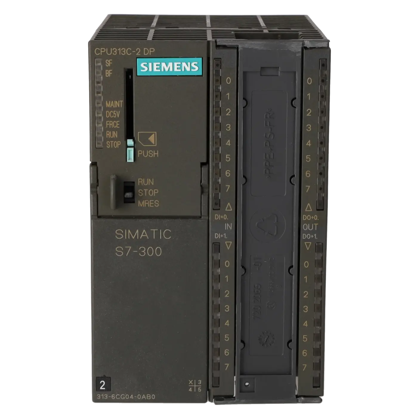
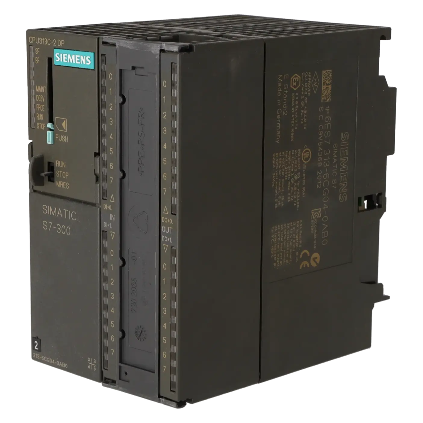
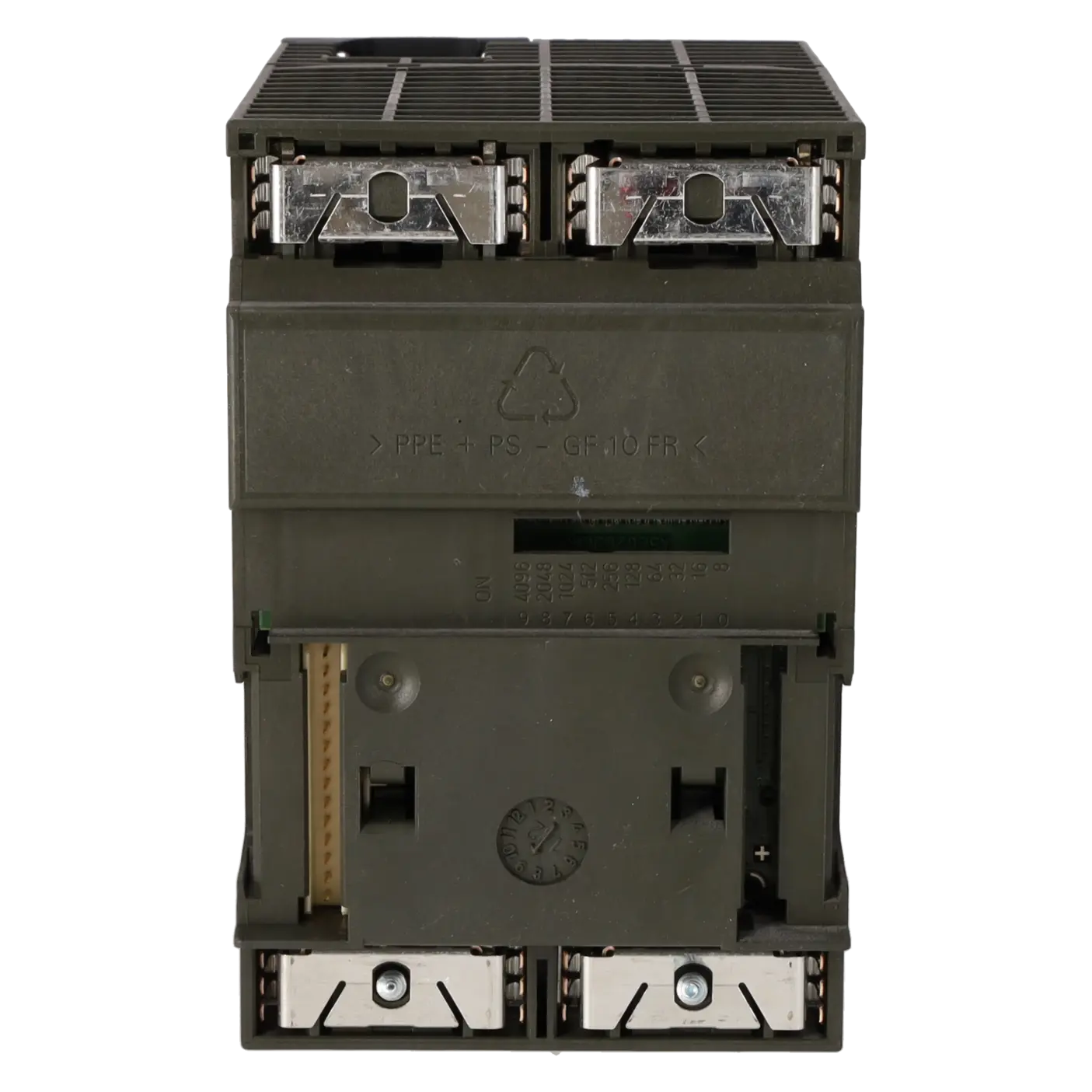
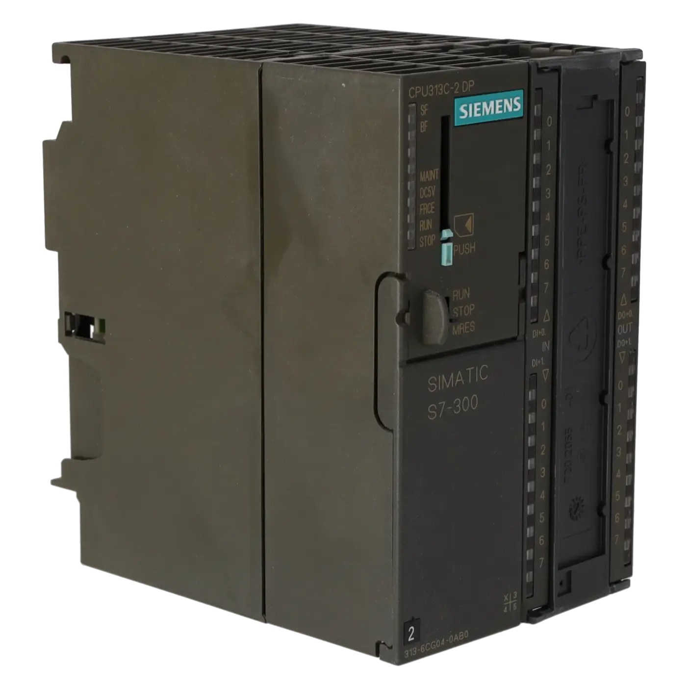
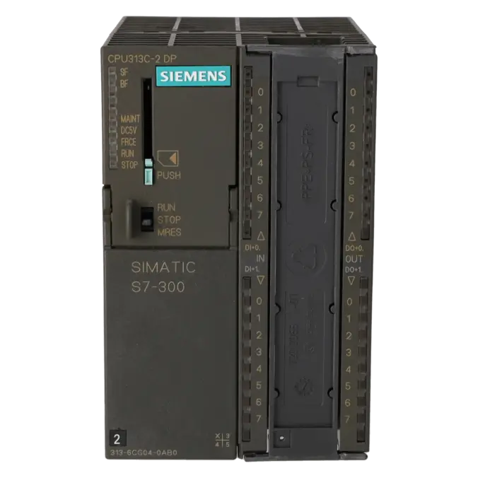
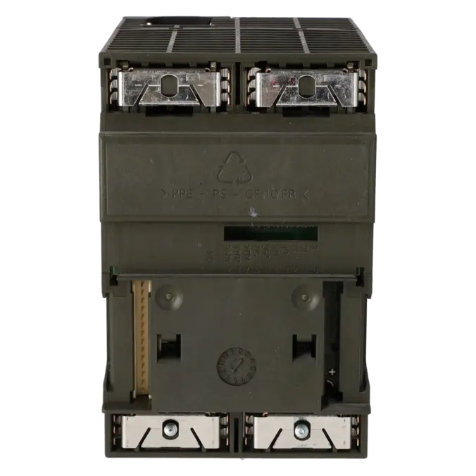
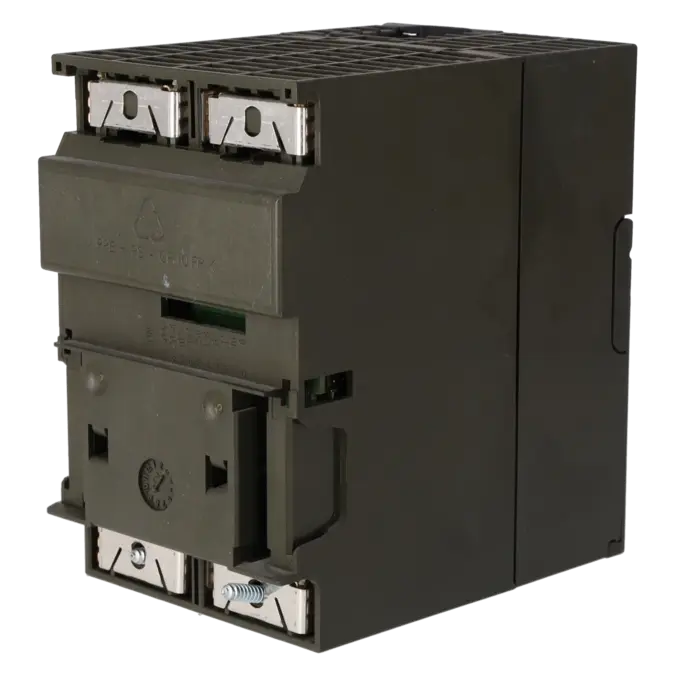
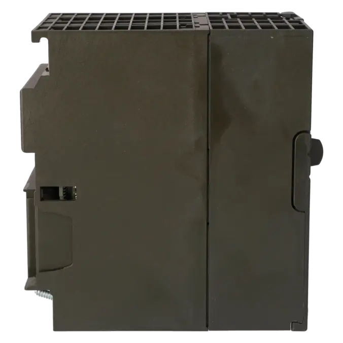
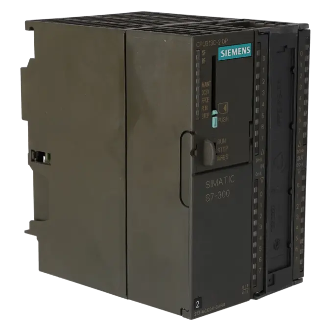
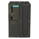
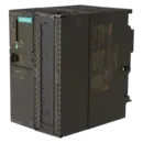
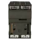
SIMATIC S7-300, CPU 313C-2 DP COMPACT CPU WITH MPI, 16 DI/16 DO, 3 HIGH-SPEED COUNTERS (30 KHZ), INTEGRATED DP INTERFACE, INTEGR. POWER SUPPLY 24 V DC, WORK MEMORY 128 KB, FRONT CONNECTOR (1X 40-POLE) AND MICRO MEMORY CARD REQUIRED
Services for SIEMENS 6ES7313-6CG04-0AB0
Repair
from 774,97 €
to 1.394,94 €
Replacement
1.742,80 €
1.307,10 €
Used
1.936,44 €
1.452,33 €
New
2.151,60 €
1.613,70 €
SIEMENS |
6ES7313-6CG04-0AB0 –
additional product information
| Delivery information | |||
|---|---|---|---|
| Export identifier | AL: N ECCN: EAR99H | ||
| Net weight | 0.56 | ||
| Quantity | 1 Stück | ||
| Packaging quantity | 1 | ||
| Additional product information | |||
|---|---|---|---|
| Product status | |||
| EAN | 4025515079071 | ||
| UPC | 040892788587 | ||
| Static lot number | 85371091 | ||
| List indicator | ST73 | ||
| Product group | 4256 | ||
| Country of origin | DE | ||
| Compliance with the substance restrictions according to RoHS directive | Since: 20110520 | ||
| Product classifications | Version | Classification | |
|---|---|---|---|
| eClass | 4 | / | |
| eClass | 5.1 | 27-24-22-07 | |
| eClass | 6.0 | 27-24-22-07 | |
| ETIM | 3 | / | |
| ETIM | 4 | EC000236 | |
| ETIM | 5 | EC000236 | |
What is the 6ES7313-6CG04-0AB0 and where is it used?
The 6ES7313-6CG04-0AB0 is a SIMATIC S7-300 CPU 313C-2 DP from Siemens. It is a compact CPU with integrated MPI/DP communication, 16 digital inputs, 16 digital outputs, 3 high-speed counters up to 30 kHz, and an integrated 24 V DC power supply. A Micro Memory Card (MMC) and a 40-pin front connector are required for operation. The module is typically used in machines and existing systems where a compact PLC with local I/O, PROFIBUS connectivity, and solid cycle performance is required. The model is particularly relevant for spare parts procurement, retrofits in existing installations, and the rapid restoration of older S7-300 systems.
Overview of the key technical data and what it means
The CPU operates on 24 V DC with a permissible range of 19.2 to 28.8 V. It features 128 KB of work memory, requires a plug-in MMC as load memory, and stores programs and data on the memory card without the need for a battery. Important for maintenance personnel: the CPU processes bit operations in a typical 0.07 µs, supports 1 integrated DP master, can connect up to 124 DP nodes, and provides 4 high-speed outputs as well as 3 counters up to 30 kHz for pulse, counting, and simple positioning tasks. With dimensions of 80 x 125 x 130 mm and a weight of approximately 500 g, it remains compact. For procurement, this means a high level of functionality in a small footprint without requiring additional CPU peripherals for standard field applications.
Product status, life-cycle status and obsolescence
Siemens officially classifies the 6ES7313-6CG04-0AB0 as a spare part. At the same time, manufacturer life-cycle information shows that the product is within a phase-out and discontinuation environment, as Siemens has already announced the phase-out of the S7-300 / ET 200M platform. For operators of existing systems, this is a clear indication that while the module remains important for ongoing operation, the risk of procurement difficulties and downtime will continue to increase over time. For modernization projects, Siemens identifies the S7-1500 as the natural successor platform. In Siemens migration guidelines, the CPU 1511C is listed as the target device for migrating a CPU 313C-2 DP. However, this is a migration path rather than a direct 1:1 replacement within an existing control cabinet.
Available EICHLER services and when they are relevant in practice
For this module, EICHLER offers several practical procurement and service options: repair within 2–5 days, exchange service within 1–3 days, used units within 1–3 days, and new units within 1–3 days. An optional test report is also available. For repairs, EICHLER explicitly includes technical cleaning, preventive maintenance, comprehensive functional testing, and a minimum 24-month warranty. This is particularly relevant for manufacturing companies where downtime costs are high, the system cannot be migrated in the short term, or identical legacy hardware must remain in operation. Exchange units and tested sales stock help to minimise downtime, while repairs and life-cycle-oriented spare parts strategies help to manage obsolescence risks in a controlled manner. EICHLER additionally provides a 24/7 spare parts service and optional warranty extensions of up to 36 months.
| Attribute | Value |
|---|---|
| General information | |
| Product type designation | CPU 313C-2 |
| HW functional status | 1 |
| Firmware version | V3.3 |
| Engineering with | |
| ● Programming package | STEP 7 V5.5 + SP1 or higher or STEP 7 V5.3 + SP2 or higher with HSP 203 |
| Supply voltage | |
| Rated value (DC) | 24 V |
| permissible range, lower limit (DC) | 19.2 V |
| permissible range, upper limit (DC) | 28.8 V |
| external protection for power supply lines (recommendation) | Miniature circuit breaker, type C; min. 2 A; miniature circuit breaker type B, min. 4 A |
| Mains buffering | |
| ● Mains/voltage failure stored energy time | 5 ms |
| ● Repeat rate, min. | 1 s |
| Load voltage L+ | |
| Digital inputs | |
| — Rated value (DC) | 24 V |
| — Reverse polarity protection | Yes |
| Digital outputs | |
| — Rated value (DC) | 24 V |
| — Reverse polarity protection | No |
| Input current | |
| Current consumption (rated value) | 800 mA |
| Current consumption (in no-load operation), typ. | 110 mA |
| Inrush current, typ. | 5 A |
| I²t | 0.7 A²·s |
| Digital inputs | |
| ● from load voltage L+ (without load), max. | 80 mA |
| Digital outputs | |
| ● from load voltage L+, max. | 50 mA |
| Power loss | |
| Power loss, typ. | 9 W |
| Memory | |
| Work memory | |
| ● integrated | 128 kbyte |
| ● expandable | No |
| Load memory | |
| ● Plug-in (MMC) | Yes |
| ● Plug-in (MMC), max. | 8 Mbyte |
| ● Data management on MMC (after last programming), min. | 10 a |
| Backup | |
| ● present | Yes; Guaranteed by MMC (maintenance-free) |
| ● without battery | Yes; Program and data |
| CPU processing times | |
| for bit operations, typ. | 0.07 µs |
| for word operations, typ. | 0.15 µs |
| for fixed point arithmetic, typ. | 0.2 µs |
| for floating point arithmetic, typ. | 0.72 µs |
| CPU-blocks | |
| Number of blocks (total) | 1 024; (DBs, FCs, FBs); the maximum number of loadable blocks can be reduced by the MMC used. |
| DB | |
| ● Number, max. | 1 024; Number range: 1 to 16000 |
| ● Size, max. | 64 kbyte |
| FB | |
| ● Number, max. | 1 024; Number range: 0 to 7999 |
| ● Size, max. | 64 kbyte |
| FC | |
| ● Number, max. | 1 024; Number range: 0 to 7999 |
| ● Size, max. | 64 kbyte |
| OB | |
| ● Number, max. | see instruction list |
| ● Size, max. | 64 kbyte |
| ● Number of free cycle OBs | 1; OB 1 |
| ● Number of time alarm OBs | 1; OB 10 |
| ● Number of delay alarm OBs | 2; OB 20, 21 |
| ● Number of cyclic interrupt OBs | 4; OB 32, 33, 34, 35 |
| ● Number of process alarm OBs | 1; OB 40 |
| ● Number of DPV1 alarm OBs | 3; OB 55, 56, 57 |
| ● Number of startup OBs | 1; OB 100 |
| ● Number of asynchronous error OBs | 5; OB 80, 82, 85, 86, 87 |
| ● Number of synchronous error OBs | 2; OB 121, 122 |
| Nesting depth | |
| ● per priority class | 16 |
| ● additional within an error OB | 4 |
| Counters, timers and their retentivity | |
| S7 counter | |
| ● Number | 256 |
| Retentivity | |
| — adjustable | Yes |
| — preset | Z 0 to Z 7 |
| Counting range | |
| — lower limit | 0 |
| — upper limit | 999 |
| IEC counter | |
| ● present | Yes |
| ● Type | SFB |
| ● Number | Unlimited (limited only by RAM capacity) |
| S7 times | |
| ● Number | 256 |
| Retentivity | |
| — adjustable | Yes |
| — preset | No retentivity |
| Time range | |
| — lower limit | 10 ms |
| — upper limit | 9 990 s |
| IEC timer | |
| ● present | Yes |
| ● Type | SFB |
| ● Number | Unlimited (limited only by RAM capacity) |
| Data areas and their retentivity | |
| Retentive data area (incl. timers, counters, flags), max. | 64 kbyte |
| Flag | |
| ● Size, max. | 256 byte |
| ● Retentivity available | Yes; MB 0 to MB 255 |
| ● Retentivity preset | MB 0 to MB 15 |
| ● Number of clock memories | 8; 1 memory byte |
| Data blocks | |
| ● Retentivity adjustable | Yes; via non-retain property on DB |
| ● Retentivity preset | Yes |
| Local data | |
| ● per priority class, max. | 32 kbyte; Max. 2048 bytes per block |
| Address area | |
| I/O address area | |
| ● Inputs | 2 048 byte |
| ● Outputs | 2 048 byte |
| of which distributed | |
| — Inputs | 2 030 byte |
| — Outputs | 2 030 byte |
| Process image | |
| ● Inputs | 2 048 byte |
| ● Outputs | 2 048 byte |
| ● Inputs, adjustable | 2 048 byte |
| ● Outputs, adjustable | 2 048 byte |
| ● Inputs, default | 128 byte |
| ● Outputs, default | 128 byte |
| Digital channels | |
| ● Inputs | 16 256 |
| — of which central | 1 008 |
| ● Outputs | 16 256 |
| — of which central | 1 008 |
| Analog channels | |
| ● Inputs | 1 015 |
| — of which central | 248 |
| ● Outputs | 1 015 |
| — of which central | 248 |
| Hardware configuration | |
| Number of expansion units, max. | 3 |
| Number of DP masters | |
| ● integrated | 1 |
| ● via CP | 4 |
| Number of operable FMs and CPs (recommended) | |
| ● FM | 8 |
| ● CP, PtP | 8 |
| ● CP, LAN | 6 |
| Rack | |
| ● Racks, max. | 4 |
| ● Modules per rack, max. | 8; In rack 3 max. 7 |
| Time of day | |
| Clock | |
| ● Hardware clock (real-time) | Yes |
| ● retentive and synchronizable | Yes |
| ● Backup time | 6 wk; At 40 °C ambient temperature |
| ● Deviation per day, max. | 10 s; Typ.: 2 s |
| ● Behavior of the clock following POWER-ON | Clock continues running after POWER OFF |
| ● Behavior of the clock following expiry of backup period | the clock continues at the time of day it had when power was switched off |
| Operating hours counter | |
| ● Number | 1 |
| ● Number/Number range | 0 |
| ● Range of values | 0 to 2^31 hours (when using SFC 101) |
| ● Granularity | 1 h |
| ● retentive | Yes; Must be restarted at each restart |
| Clock synchronization | |
| ● supported | Yes |
| ● to MPI, master | Yes |
| ● on MPI, device | Yes |
| ● to DP, master | Yes; With DP slave only slave clock |
| ● on DP, device | Yes |
| ● in AS, master | Yes |
| ● in AS, device | No |
| Digital inputs | |
| Number of digital inputs | 16 |
| ● of which inputs usable for technological functions | 12 |
| integrated channels (DI) | 16 |
| Input characteristic curve in accordance with IEC 61131, type 1 | Yes |
| Number of simultaneously controllable inputs | |
| horizontal installation | |
| — up to 40 °C, max. | 16 |
| — up to 60 °C, max. | 8 |
| vertical installation | |
| — up to 40 °C, max. | 8 |
| Input voltage | |
| ● Rated value (DC) | 24 V |
| ● for signal "0" | -3 to +5V |
| ● for signal "1" | +15 to +30 V |
| Input current | |
| ● for signal "1", typ. | 8 mA |
| Input delay (for rated value of input voltage) | |
| for standard inputs | |
| — parameterizable | Yes; 0.1 / 0.3 / 3 / 15 ms (You can reconfigure the input delay of the standard inputs during program runtime. Please note that under certain circumstances your newly set filter time may not be effective until the next filter cycle.) |
| — Rated value | 3 ms |
| for technological functions | |
| — at "0" to "1", max. | 16 µs; Minimum pulse width/minimum pause between pulses at maximum counting frequency |
| Cable length | |
| ● shielded, max. | 1 000 m; 100 m for technological functions |
| ● unshielded, max. | 600 m; for technological functions: No |
| for technological functions | |
| — shielded, max. | 100 m; at maximum count frequency |
| — unshielded, max. | not allowed |
| Digital outputs | |
| Number of digital outputs | 16 |
| ● of which high-speed outputs | 4; Notice: You cannot connect the fast outputs of your CPU in parallel |
| integrated channels (DO) | 16 |
| Short-circuit protection | Yes; Clocked electronically |
| ● Response threshold, typ. | 1 A |
| Limitation of inductive shutdown voltage to | L+ (-48 V) |
| Controlling a digital input | Yes |
| Switching capacity of the outputs | |
| ● on lamp load, max. | 5 W |
| Load resistance range | |
| ● lower limit | 48 Ω |
| ● upper limit | 4 kΩ |
| Output voltage | |
| ● for signal "1", min. | L+ (-0.8 V) |
| Output current | |
| ● for signal "1" rated value | 500 mA |
| ● for signal "1" permissible range, min. | 5 mA |
| ● for signal "1" permissible range, max. | 0.6 A |
| ● for signal "1" minimum load current | 5 mA |
| ● for signal "0" residual current, max. | 0.5 mA |
| Parallel switching of two outputs | |
| ● for uprating | No |
| ● for redundant control of a load | Yes |
| Switching frequency | |
| ● with resistive load, max. | 100 Hz |
| ● with inductive load, max. | 0.5 Hz |
| ● on lamp load, max. | 100 Hz |
| ● of the pulse outputs, with resistive load, max. | 2.5 kHz |
| Total current of the outputs (per group) | |
| horizontal installation | |
| — up to 40 °C, max. | 3 A |
| — up to 60 °C, max. | 2 A |
| vertical installation | |
| — up to 40 °C, max. | 2 A |
| Cable length | |
| ● shielded, max. | 1 000 m |
| ● unshielded, max. | 600 m |
| Analog inputs | |
| Number of analog inputs | 0 |
| integrated channels (AI) | 0 |
| Analog outputs | |
| integrated channels (AO) | 0 |
| Encoder | |
| Connectable encoders | |
| ● 2-wire sensor | Yes |
| — permissible quiescent current (2-wire sensor), max. | 1.5 mA |
| Interfaces | |
| Number of PROFINET interfaces | 0 |
| Number of RS 485 interfaces | 2; MPI and PROFIBUS DP |
| Number of RS 422 interfaces | 0 |
| 1. Interface | |
| Interface type | Integrated RS 485 interface |
| Isolated | No |
| Interface types | |
| ● RS 485 | Yes |
| ● Output current of the interface, max. | 200 mA |
| Protocols | |
| ● MPI | Yes |
| ● PROFIBUS DP master | No |
| ● PROFIBUS DP device | No |
| ● Point-to-point connection | No |
| MPI | |
| ● Transmission rate, max. | 187.5 kbit/s |
| Services | |
| — PG/OP communication | Yes |
| — Routing | Yes |
| — Global data communication | Yes |
| — S7 basic communication | Yes |
| — S7 communication | Yes; Only server, configured on one side |
| — S7 communication, as client | No; but via CP and loadable FB |
| — S7 communication, as server | Yes |
| 2. Interface | |
| Interface type | Integrated RS 485 interface |
| Isolated | Yes |
| Interface types | |
| ● RS 485 | Yes |
| ● Output current of the interface, max. | 200 mA |
| Protocols | |
| ● MPI | No |
| ● PROFINET IO Controller | No |
| ● PROFINET IO Device | No |
| ● PROFINET CBA | No |
| ● PROFIBUS DP master | Yes |
| ● PROFIBUS DP device | Yes |
| PROFIBUS DP master | |
| ● Transmission rate, max. | 12 Mbit/s |
| ● max. number of DP devices | 124 |
| Services | |
| — PG/OP communication | Yes |
| — Routing | Yes |
| — Global data communication | No |
| — S7 basic communication | Yes; I blocks only |
| — S7 communication | Yes; Yes (only server; connection configured at one end) |
| — S7 communication, as client | No |
| — S7 communication, as server | Yes |
| — Equidistance | Yes |
| — Isochronous mode | No |
| — SYNC/FREEZE | Yes |
| — activation/deactivation of DP devices | Yes |
| — max. number of DP devices that can be activated/deactivated at the same time | 8 |
| — Direct data exchange (slave-to-slave communication) | Yes; as subscriber |
| — DPV1 | Yes |
| Address area | |
| — Inputs, max. | 2 kbyte |
| — Outputs, max. | 2 kbyte |
| User data per DP device | |
| — Inputs, max. | 244 byte |
| — Outputs, max. | 244 byte |
| PROFIBUS DP device | |
| ● GSD file | The latest GSD file is available on the Internet (http://www.siemens.com/profibus-gsd) |
| ● Transmission rate, max. | 12 Mbit/s |
| ● automatic baud rate search | Yes; only with passive interface |
| ● Address area, max. | 32 |
| ● User data per address area, max. | 32 byte |
| Services | |
| — PG/OP communication | Yes |
| — Routing | Yes; Only with active interface |
| — Global data communication | No |
| — S7 basic communication | No |
| — S7 communication | Yes; Yes (only server; connection configured at one end) |
| — S7 communication, as client | No |
| — S7 communication, as server | Yes |
| — Direct data exchange (slave-to-slave communication) | Yes |
| — DPV1 | No |
| Transfer memory | |
| — Inputs | 244 byte |
| — Outputs | 244 byte |
| Protocols | |
| PROFIsafe | No |
| Communication functions | |
| PG/OP communication | Yes |
| Data record routing | Yes |
| Global data communication | |
| ● supported | Yes |
| ● Number of GD loops, max. | 8 |
| ● Number of GD packets, max. | 8 |
| ● Number of GD packets, transmitter, max. | 8 |
| ● Number of GD packets, receiver, max. | 8 |
| ● Size of GD packets, max. | 22 byte |
| ● Size of GD packet (of which consistent), max. | 22 byte |
| S7 basic communication | |
| ● supported | Yes |
| ● User data per job, max. | 76 byte |
| ● User data per job (of which consistent), max. | 76 byte; 76 bytes (with X_SEND or X_RCV); 64 bytes (with X_PUT or X_GET as server) |
| S7 communication | |
| ● supported | Yes |
| ● as server | Yes |
| ● as client | Yes; Via CP and loadable FB |
| ● User data per job, max. | 180 kbyte; With PUT/GET |
| ● User data per job (of which consistent), max. | 240 byte; as server |
| S5 compatible communication | |
| ● supported | Yes; via CP and loadable FC |
| Number of connections | |
| ● overall | 8 |
| ● usable for PG communication | 7 |
| — reserved for PG communication | 1 |
| — adjustable for PG communication, min. | 1 |
| — adjustable for PG communication, max. | 7 |
| ● usable for OP communication | 7 |
| — reserved for OP communication | 1 |
| — adjustable for OP communication, min. | 1 |
| — adjustable for OP communication, max. | 7 |
| ● usable for S7 basic communication | 4 |
| — reserved for S7 basic communication | 0 |
| — adjustable for S7 basic communication, min. | 0 |
| — adjustable for S7 basic communication, max. | 4 |
| ● usable for routing | 4; max. |
| S7 message functions | |
| Number of login stations for message functions, max. | 8; Depending on the configured connections for PG/OP and S7 basic communication |
| Process diagnostic messages | Yes |
| simultaneously active Alarm_S blocks, max. | 300 |
| Test commissioning functions | |
| Status block | Yes; Up to 2 simultaneously |
| Single step | Yes |
| Number of breakpoints | 4 |
| Status/control | |
| ● Status/control variable | Yes |
| ● Variables | Inputs, outputs, memory bits, DB, times, counters |
| ● Number of variables, max. | 30 |
| — of which status variables, max. | 30 |
| — of which control variables, max. | 14 |
| Forcing | |
| ● Forcing | Yes |
| ● Forcing, variables | Inputs, outputs |
| ● Number of variables, max. | 10 |
| Diagnostic buffer | |
| ● present | Yes |
| ● Number of entries, max. | 500 |
| — adjustable | No |
| — of which powerfail-proof | 100; Only the last 100 entries are retained |
| ● Number of entries readable in RUN, max. | 499 |
| — adjustable | Yes; From 10 to 499 |
| — preset | 10 |
| Service data | |
| ● can be read out | Yes |
| Interrupts/diagnostics/status information | |
| Diagnostics indication LED | |
| ● Status indicator digital input (green) | Yes |
| ● Status indicator digital output (green) | Yes |
| Integrated Functions | |
| Counter | |
| ● Number of counters | 3; See "Technological Functions" manual |
| ● Counting frequency, max. | 30 kHz |
| Frequency measurement | Yes |
| ● Number of frequency meters | 3; up to 30 kHz (see "Technological Functions" manual) |
| controlled positioning | No |
| integrated function blocks (closed-loop control) | Yes; PID controller (see "Technological Functions" manual) |
| PID controller | Yes |
| Number of pulse outputs | 3; Pulse width modulation up to 2.5 kHz (see "Technological Functions" Manual) |
| Limit frequency (pulse) | 2.5 kHz |
| Potential separation | |
| Potential separation digital inputs | |
| ● Potential separation digital inputs | Yes |
| ● between the channels | No |
| ● between the channels and backplane bus | Yes |
| Potential separation digital outputs | |
| ● Potential separation digital outputs | Yes |
| ● between the channels | Yes |
| ● between the channels, in groups of | 8 |
| ● between the channels and backplane bus | Yes |
| Isolation | |
| Isolation tested with | 600 V DC |
| Ambient conditions | |
| Ambient temperature during operation | |
| ● min. | 0 °C |
| ● max. | 60 °C |
| Configuration | |
| Configuration software | |
| ● STEP 7 | Yes; STEP 7 V5.5 + SP1 or higher or STEP 7 V5.3 + SP2 or higher with HSP 203 |
| ● STEP 7 Lite | No |
| Programming | |
| ● Command set | see instruction list |
| ● Nesting levels | 8 |
| ● System functions (SFC) | see instruction list |
| ● System function blocks (SFB) | see instruction list |
| Programming language | |
| — LAD | Yes |
| — FBD | Yes |
| — STL | Yes |
| — SCL | Yes |
| — CFC | Yes |
| — GRAPH | Yes |
| — HiGraph® | Yes |
| Know-how protection | |
| ● User program protection/password protection | Yes |
| ● Block encryption | Yes; With S7 block Privacy |
| Dimensions | |
| Width | 80 mm |
| Height | 125 mm |
| Depth | 130 mm |
| Weights | |
| Weight, approx. | 500 g |
| Fault description | Possible solution |
|---|---|
| Why is the STOP LED on the 6ES7313-6CG04-0AB0 flashing slowly? | A slowly flashing STOP LED on an S7-300 CPU typically indicates that a memory reset (MRES) has been requested, for example after replacing the MMC or following an operating system update. Ensure that the MMC is correctly inserted, the power supply is stable, and the MRES procedure is performed according to Siemens specifications. Afterwards, the hardware configuration and user program must be downloaded again. |
| Why can't the CPU 313C-2 DP be found via MPI? | In many cases, the PG/PC interface settings, MPI address, or transmission rate do not match. First, set the PG/PC interface explicitly to MPI and then check under “Accessible Nodes” whether the CPU is visible. If the CPU still cannot be detected, inspect the MPI cable, bus connector, and the actual communication interface being used. In addition, the PROFIBUS DP interface can be tested as an alternative communication path. |
| Why are the BF and SF LEDs illuminated on the CPU 313C-2 DP? | In PROFIBUS configurations, BF (Bus Fault) usually indicates that a configured slave is not reachable or that an address assignment is incorrect. SF (System Fault) often appears as a secondary diagnostic message. Check the bus termination, slave addresses, wiring, slave power supplies, and the downloaded hardware configuration. Afterwards, evaluate the diagnostic buffer, as the CPU can store up to 500 diagnostic entries that provide detailed information about the cause of the fault. |
| Why are the integrated inputs and outputs of the CPU not responding? | On compact CPUs, the integrated I/O channels are part of the CPU itself. Therefore, first verify the 24 V load voltage (L+), the correct front connector, and the actual field wiring. If the input LEDs respond but the outputs do not switch, additionally check the signal states in a VAT (Variable Table) and review the group currents, short-circuit protection, and the application logic within OB1 |
Does the 6ES7313-6CG04-0AB0 require a Micro Memory Card and a front connector?
Yes. The CPU requires a SIMATIC Micro Memory Card (MMC) as load memory and a 40-pin front connector for operation. Without an MMC, the module is not fully operational in practical applications. This is important for procurement and maintenance because not only the CPU itself but also the required accessories must be available when ordering a replacement part.
Which software is required to configure this CPU?
Siemens specifies STEP 7 V5.5 + SP1 or STEP 7 V5.3 + SP2 with HSP 203 as suitable engineering environments for the CPU 313C-2 DP. For operators of older systems, this is a crucial consideration: before replacing the CPU, modifying the program, or commissioning the system, it should be verified that the existing engineering environment supports the required software version. This helps avoid delays during commissioning and service.
Does the CPU support PROFINET?
No. The 6ES7313-6CG04-0AB0 supports MPI and PROFIBUS DP, but it does not support PROFINET. The model is therefore clearly designed for traditional S7-300 and PROFIBUS architectures. If Ethernet-based communication or modern PROFINET topologies are required, the existing architecture must be supplemented with additional components or a planned migration to a newer controller platform should be considered.
Can the CPU operate as both a PROFIBUS DP master and a DP slave?
Yes. According to Siemens, the integrated DP interface supports both PROFIBUS DP master and PROFIBUS DP device (slave) operation. As a master, transmission rates of up to 12 Mbit/s are supported, and Siemens specifies support for up to 124 DP devices. This flexibility is particularly useful in existing installations, allowing the CPU to be integrated into both traditional master-slave architectures and more complex decentralised I/O systems.
What is the fastest solution if a machine using this CPU is down?
If production must resume as quickly as possible, an exchange unit is often the fastest option, as EICHLER specifies a delivery time of 1–3 days. Used and new units are also listed with 1–3 day availability, while repair services are typically specified at 2–5 days. For procurement and maintenance teams, this distinction is important because the most economical solution is not always the least expensive one, but often the one that restores operation in the shortest possible time.
Is there a direct successor or a recommended migration path?
Siemens positions the S7-1500 as the natural successor platform to the ageing S7-300 family. In the official migration guide, the 6ES7313-6CG04-0AB0 is mapped to a CPU 1511C. For plant operators, this means there is a clear modernisation path, but not a direct plug-and-play replacement within an existing control cabinet. If short-term availability is the priority, repair, exchange, or strategic spare-part stocking are often the better options. For medium- to long-term modernisation projects, however, a structured migration to the S7-1500 platform should be considered.