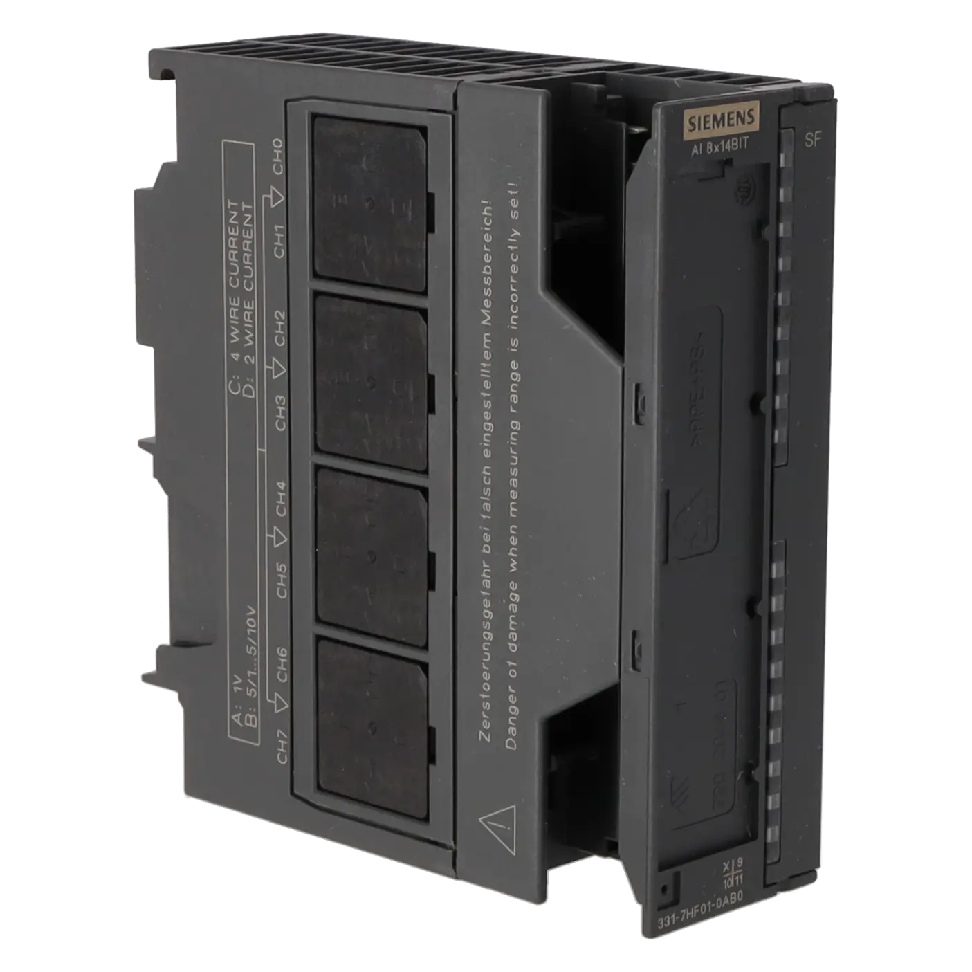

SIEMENS 6ES7331-7HF01-0AB0
-
SIEMENS | PLC Controls | Analog Input / Output Modules
- EICHLER-art.no.: K0136705
- EAN: 4025515070979
- UPC: 662643118063
Product description
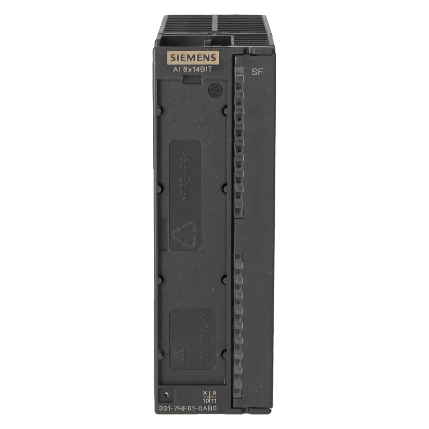
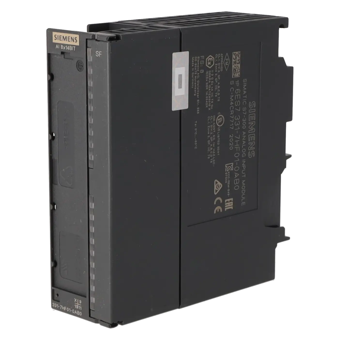
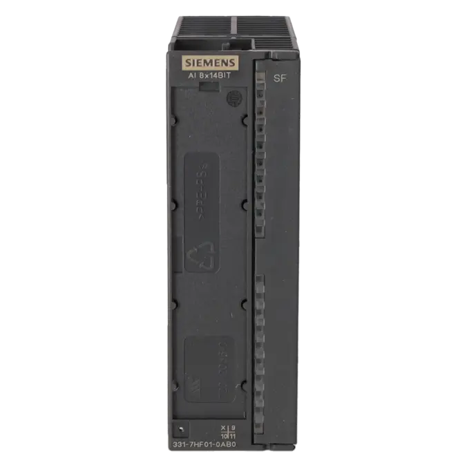
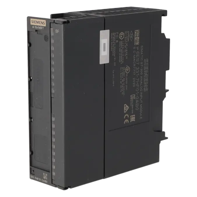
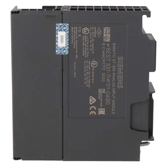
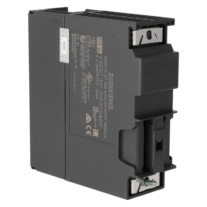
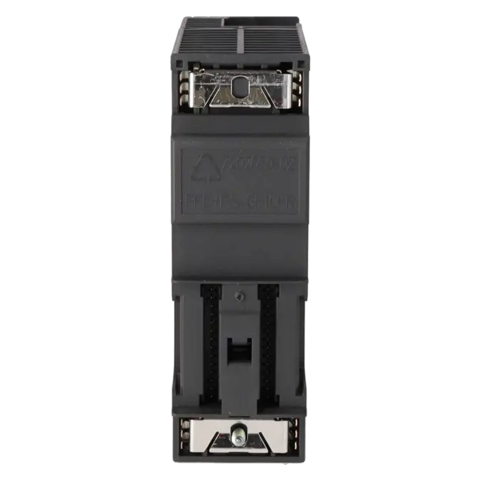
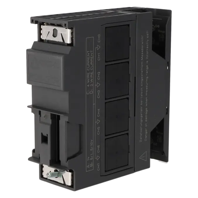
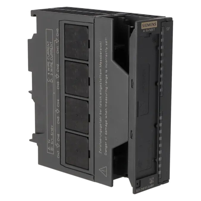
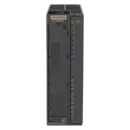
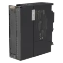
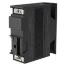
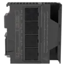
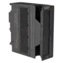
SIMATIC S7-300, ANALOG INPUT SM 331, ISOLATED, 8 AI, RESOLUTION 14 BIT, 0.052 MS/CHANNEL CURRENT, VOLTAGE ALARM, DIAGNOSTICS, 1X 20-POLE, SUITABLE FOR ISOCHRONOUS MODE IMPROVED BUS CYCLE TIME FOR ISOCHRONOUS MODE
Services for SIEMENS 6ES7331-7HF01-0AB0
Repair
from 440,56 €
to 793,00 €
Replacement
1.028,21 €
771,16 €
Used
1.142,47 €
856,85 €
New
1.269,40 €
952,05 €
SIEMENS |
6ES7331-7HF01-0AB0 –
additional product information
| Delivery information | |||
|---|---|---|---|
| Export identifier | AL: N ECCN: EAR99H | ||
| Net weight | 0.289 | ||
| Quantity | 1 Stück | ||
| Packaging quantity | 1 | ||
| Additional product information | |||
|---|---|---|---|
| Product status | EOP: 2025-10-01 | ||
| EAN | 4025515070979 | ||
| UPC | 662643118063 | ||
| Static lot number | 85389091 | ||
| List indicator | ST73 | ||
| Product group | 4561 | ||
| Country of origin | DE | ||
| Compliance with the substance restrictions according to RoHS directive | Since: 20080331 | ||
| Product classifications | Version | Classification | |
|---|---|---|---|
| eClass | 4 | 27-24-03-05 | |
| eClass | 5.1 | 27-24-22-01 | |
| eClass | 6.0 | 27-24-22-01 | |
| ETIM | 3 | / | |
| ETIM | 4 | EC001420 | |
| ETIM | 5 | EC001420 | |
What is 6ES7331-7HF01-0AB0 and where is it used?
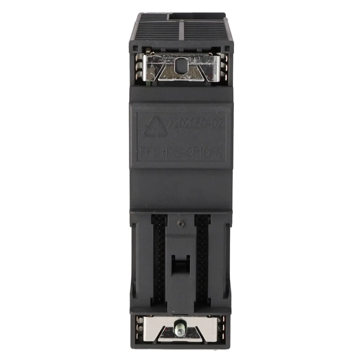
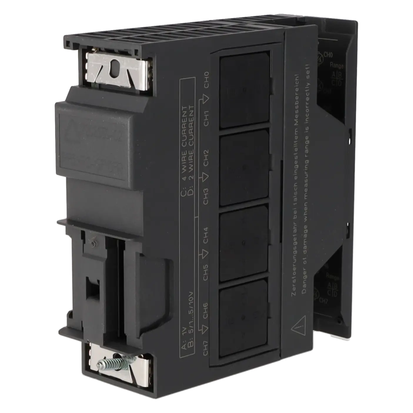
The 6ES7331-7HF01-0AB0 is a SIMATIC S7-300 SM 331 analogue input module from Siemens. It acquires 8 analogue input signals and is designed for voltage and current measurements in industrial automation. Typical applications include systems with pressure, level, position, flow, or speed sensors where fast and repeatable signal acquisition is essential. The module is intended for use in S7-300 stations and is also used in isochronous applications where process values must be processed with precise timing. For maintenance and spare-parts procurement, it is particularly relevant when existing installations need to remain in reliable operation.
Overview of the most important technical data and what they mean
The module features 8 analogue inputs arranged in 4 channel groups, meaning that two channels share the same parameterisation. Supported signal ranges include 1 to 5 V, ±1 V, ±5 V, ±10 V, 0 to 20 mA, ±20 mA, and 4 to 20 mA. The maximum 14-bit resolution provides precise signal representation, while the basic conversion time of 52 µs per channel (0.052 ms/channel) enables rapid signal updates. The module requires 24 V DC, has a typical power loss of 1.5 W, supports shielded cable lengths of up to 200 m, and offers diagnostic alarms, limit-value alarms, and isochronous operation. For accurate process monitoring, it is also important to note that the inputs are not galvanically isolated from each other but are isolated from the backplane bus and electronics supply.
Product status, life-cycle status and obsolescence
Siemens lists the 6ES7331-7HF01-0AB0 with the life-cycle status “Product Cancellation”; in the current Siemens datasheet, the module is also designated as a spare part. On the EICHLER product page, an EOP (End of Product) date of 01 October 2025 is specified. For operators, this means that the module clearly belongs to the area of installed-base support rather than new system design.
A direct, backplane-compatible plug-and-play successor for the same S7-300 module is not publicly specified by Siemens. For migration projects, Siemens refers to S7-1500 alternatives such as 6ES7531-7KF00-0BA0 and 6ES7531-7NF10-0AB0. Within the ET 200SP HA upgrade environment, Siemens also identifies 6DL1134-6TH00-0PH1 as a migration path for this module. However, these are migration or upgrade options rather than direct 1:1 replacement modules for existing S7-300 racks.
Available EICHLER services and when they are relevant in practice
EICHLER offers several practical options to ensure system availability for this module. Repair is particularly suitable when the module is critical to production but the existing hardware and software environment should remain unchanged. According to the product page, repair includes technical cleaning, preventive maintenance, comprehensive functional testing, and a minimum 24-month warranty.
Exchange is the preferred option in the event of an urgent breakdown when a working replacement unit is required quickly. Used units are attractive for cost-conscious maintenance strategies, while new units are suitable for spare-stock building or planned replacements. In addition, a test report for analogue input/output modules can be ordered, which is especially valuable in quality-sensitive production environments where documented measurement accuracy and functionality are required.
| Attribute | Value |
|---|---|
| General information | |
| Product function | |
| ● Isochronous mode | Yes |
| Supply voltage | |
| Load voltage L+ | |
| ● Rated value (DC) | 24 V |
| ● Reverse polarity protection | Yes |
| Input current | |
| from load voltage L+ (without load), max. | 50 mA |
| from backplane bus 5 V DC, max. | 100 mA |
| Power loss | |
| Power loss, typ. | 1.5 W |
| Analog inputs | |
| Number of analog inputs | 8 |
| permissible input voltage for voltage input (destruction limit), max. | 20 V; 20 V DC permanent, 75 V DC for max. 1 s (duty factor 1:20) |
| permissible input current for current input (destruction limit), max. | 40 mA |
| Input ranges | |
| ● Voltage | Yes |
| ● Current | Yes |
| ● Thermocouple | No |
| ● Resistance thermometer | No |
| ● Resistance | No |
| Input ranges (rated values), voltages | |
| ● 0 to +10 V | No |
| ● 1 V to 5 V | Yes |
| — Input resistance (1 V to 5 V) | 100 kΩ |
| ● -1 V to +1 V | Yes |
| — Input resistance (-1 V to +1 V) | 10 MΩ |
| ● -10 V to +10 V | Yes |
| — Input resistance (-10 V to +10 V) | 100 kΩ |
| ● -5 V to +5 V | Yes |
| — Input resistance (-5 V to +5 V) | 100 kΩ |
| ● -500 mV to +500 mV | Yes |
| ● -80 mV to +80 mV | Yes |
| Input ranges (rated values), currents | |
| ● 0 to 20 mA | Yes |
| — Input resistance (0 to 20 mA) | 50 Ω |
| ● -20 mA to +20 mA | Yes |
| — Input resistance (-20 mA to +20 mA) | 50 Ω |
| ● 4 mA to 20 mA | Yes |
| — Input resistance (4 mA to 20 mA) | 50 Ω |
| Cable length | |
| ● shielded, max. | 200 m |
| Analog value generation for the inputs | |
| Integration and conversion time/resolution per channel | |
| ● Resolution with overrange (bit including sign), max. | 14 bit; Unipolar: 14 bit; bipolar: 13 bit + sign |
| ● Integration time, parameterizable | Yes |
| ● Basic conversion time (ms) | 52 µs per channel |
| ● Interference voltage suppression for interference frequency f1 in Hz | none / 400 / 60 / 50 Hz |
| Encoder | |
| Connection of signal encoders | |
| ● for current measurement as 2-wire transducer | Yes |
| ● for current measurement as 4-wire transducer | Yes |
| Errors/accuracies | |
| Operational error limit in overall temperature range | |
| ● Voltage, relative to input range, (+/-) | 0.4 % |
| ● Current, relative to input range, (+/-) | 0.3 % |
| Basic error limit (operational limit at 25 °C) | |
| ● Voltage, relative to input range, (+/-) | 0.25 % |
| ● Current, relative to input range, (+/-) | 0.2 % |
| Interrupts/diagnostics/status information | |
| Diagnostics function | Yes |
| Alarms | |
| ● Diagnostic alarm | Yes; Parameterizable |
| ● Limit value alarm | Yes; Parameterizable, channels 0 and 2 |
| Diagnoses | |
| ● Diagnostic information readable | Yes |
| Diagnostics indication LED | |
| ● Group error SF (red) | Yes |
| Potential separation | |
| Potential separation analog inputs | |
| ● between the channels | No |
| ● between the channels and backplane bus | Yes |
| ● between the channels and the power supply of the electronics | Yes |
| Isolation | |
| Isolation tested with | 500 V DC |
| Connection method | |
| required front connector | 20-pin |
| Dimensions | |
| Width | 40 mm |
| Height | 125 mm |
| Depth | 117 mm |
| Weights | |
| Weight, approx. | 230 g |
| Fault description | Possible solution |
|---|---|
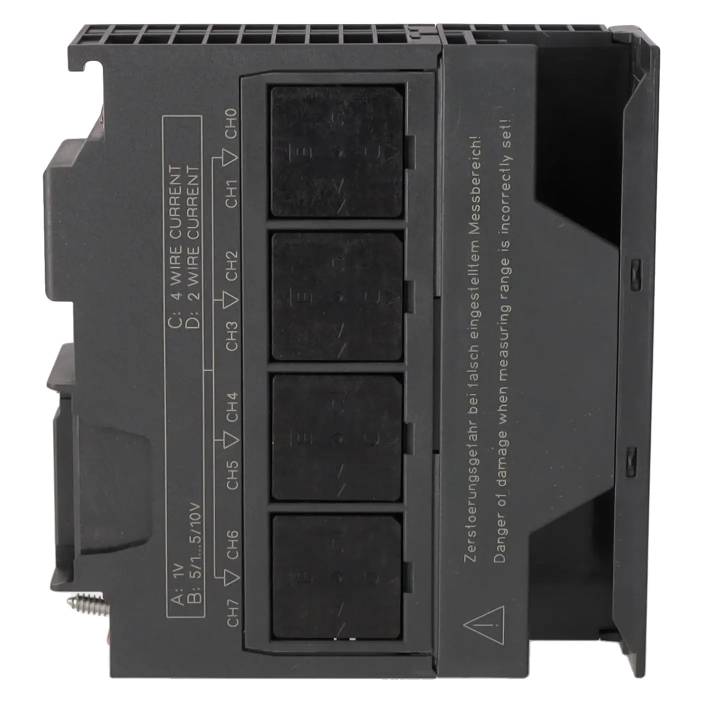
| Why does the 6ES7331-7HF01-0AB0 permanently display 32672 or 7FFF with a 4–20 mA transmitter? | A parameterisation or wiring error is often the cause. Siemens states that an overflow is triggered by an input value above the permissible overrange limit or by an incorrectly selected measuring range. In practice, this frequently occurs when the measuring range modules on the side of the card do not match the hardware configuration or when an active 4-wire transmitter has been configured as a 2-wire transmitter. Therefore, first check the STEP 7 parameter settings, then the position of the measuring range modules for each channel group, and finally verify whether the transmitter type is configured as 2DMU or 4DMU. |
| Why is the red SF LED lit on the 6ES7331-7HF01-0AB0 even though only some of the channels are being used? | On this module, unused inputs can generate a group fault if diagnostics are enabled. Siemens explicitly describes how unused channels on the 7HF0x series must be handled depending on the measurement type. For 2-wire current measurement, unused inputs may only remain open-circuit if channel-group diagnostics are disabled; otherwise, the unused input must be terminated appropriately. In addition, the online module diagnostics in STEP 7 should always be evaluated, as they identify the exact channel causing the fault. |
| Why does the 6ES7331-7HF01-0AB0 report a wire break or underrange with a 4–20 mA signal? | Siemens documents that the line monitoring function of the 7HF0x series reports a wire break in the 4 to 20 mA measuring range as soon as the current falls below 1.185 mA. An underrange condition may also be caused by an incorrect measuring range selection or reversed sensor wiring. Therefore, check the transmitter supply voltage, the shunt/series connection within the channel group, the polarity, and whether line monitoring has been enabled. If diagnostic interrupts are not used, the diagnostic bytes must be evaluated within the user program, as the SF LED alone only provides a general fault indication. |
| Why do I get common-mode errors or heavily fluctuating measured values? | Siemens identifies an excessive potential difference between the inputs and MANA as a possible cause. In this case, M− should be connected to MANA, and the wiring should be checked for reference potential issues, open circuits, and unnecessary parallel connections. In practice, an additional parameterisation adapter or a second non-isolated device connected to the circuit can also distort the measurement. In such cases, disconnecting the external device or using an isolation amplifier is often the only effective solution. Shielded cables and proper grounding should also be used. |
| Why does the module report “external load voltage missing” or provide implausible values when no sensor supply is available? | Siemens lists a missing L+ supply as a dedicated diagnostic cause. The 6ES7331-7HF01-0AB0 requires a 24 V DC load voltage, and for 2-wire transmitters the sensor supply is also provided through the module. If this voltage is missing or collapses under load, diagnostic messages and implausible process values can occur. Therefore, first check the 24 V supply, terminal connections, front connector, fuse, and voltage drop under load. If the problem recurs, a functional test of the module is recommended to rule out faults in the internal sensor supply circuitry. |
Is the 6ES7331-7HF01-0AB0 still part of the regular Siemens product life cycle?
No. Today, the module clearly belongs to the installed-base support environment. Siemens lists it with the life-cycle status “Product Cancellation” and at the same time designates it as a spare part in the datasheet. The EICHLER product page additionally specifies an EOP date of 01 October 2025. For operators, this means that the module remains relevant for existing installations, but long-term availability should be secured through repair, exchange, spare-stock management, or migration planning.
Which input signals are supported by the 6ES7331-7HF01-0AB0?
The module supports voltage and current signals but does not support resistance, RTD, or thermocouple inputs. Supported voltage ranges include 1 to 5 V, ±1 V, ±5 V, ±10 V, ±500 mV, and ±80 mV. Supported current ranges include 0 to 20 mA, ±20 mA, and 4 to 20 mA. This makes the module particularly suitable for standard process instrumentation using transmitters with conventional industrial interfaces. For direct temperature sensors without a transmitter, however, this module is not the appropriate choice.
Can I use both 2-wire and 4-wire transmitters with this module?
Yes. The module supports both 2-wire and 4-wire current transmitters. However, it is essential that the wiring, measuring-range module settings, and STEP 7 parameterisation are configured consistently. On the 7HF01, the channels are arranged in pairs, meaning that many settings apply to two channels simultaneously. This is a common source of faults in practice: an active transmitter may be configured as a 2-wire device, or a measuring-range module may be set incorrectly. If mixed configurations are required, the channel groups should be planned carefully and the module switch settings must match the hardware configuration exactly.
When should I use Fast Mode and when is Standard Mode the better choice?
Fast Mode is available only on the 6ES7331-7HF01-0AB0 and is relevant exclusively in isochronous applications. Its main advantage is a shorter minimum DP cycle time, which can be beneficial in highly time-critical applications. However, Siemens explicitly states that diagnostic functions are disabled when Fast Mode is active. Therefore, in systems where fault diagnostics and condition monitoring are important, Standard Mode is often the better choice. Fast Mode is most suitable when deterministic cycle times are more important than detailed module diagnostics.
Is there a direct Siemens successor to the 6ES7331-7HF01-0AB0?
Siemens does not publicly specify a direct plug-and-play successor for the same S7-300 rack. For migrations to the S7-1500 platform, Siemens refers to 6ES7531-7KF00-0BA0 and 6ES7531-7NF10-0AB0. For ET 200SP HA upgrade projects, Siemens additionally identifies 6DL1134-6TH00-0PH1 as a migration path. It is important to note that these are migration and upgrade options, not direct 1:1 replacement modules for an existing S7-300 rack. Operators looking to minimise downtime should therefore consider spare-part stocking, repair options, and long-term migration planning together.
How can downtime risks for this module be reduced in the short term?
In the event of a failure, four practical options are available: repair, exchange, used replacement modules, or new stock units. EICHLER offers all of these options for the 6ES7331-7HF01-0AB0. For operators with validated installations, repair is often the most economical solution when the existing hardware revision and project configuration should remain unchanged. Where production pressure is high, an exchange unit is usually the fastest route back to operation. For maintenance and purchasing departments, the optional test report can also be valuable, as it provides documented proof of functionality and supports internal quality and acceptance requirements.