


SIEMENS 6AV3688-3ED13-0AX0
-
SIEMENS | HMI | Keyboards
- EICHLER-art.no.: K0116677
- EAN: 4025515133971
- UPC: 662643028270
Product description
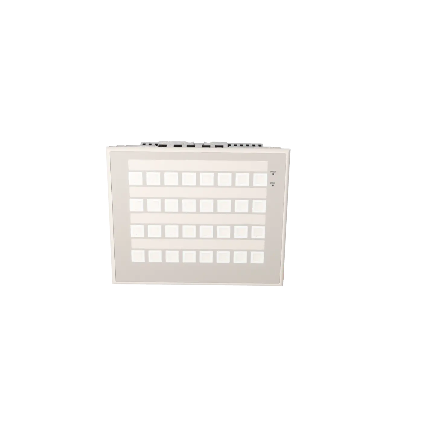
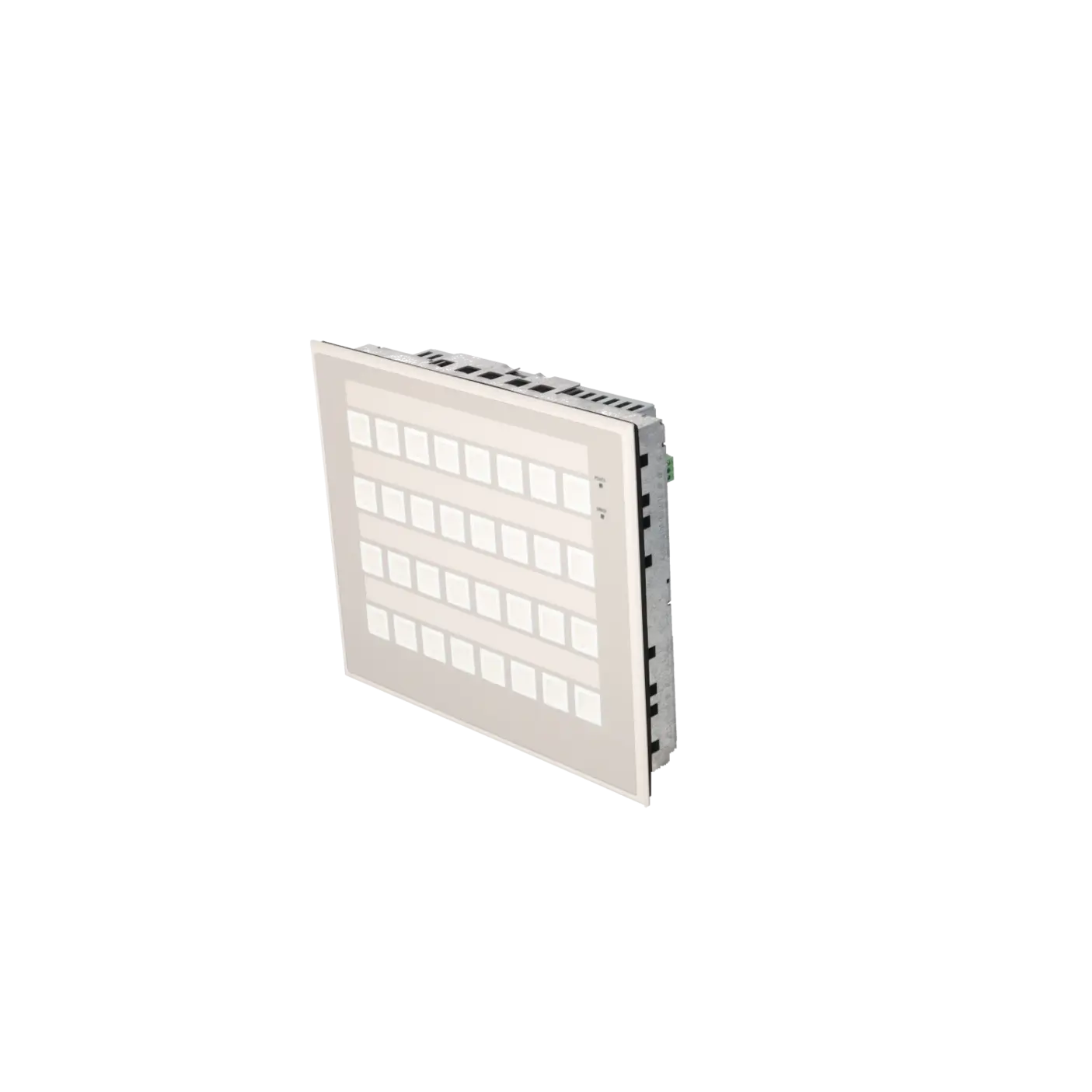
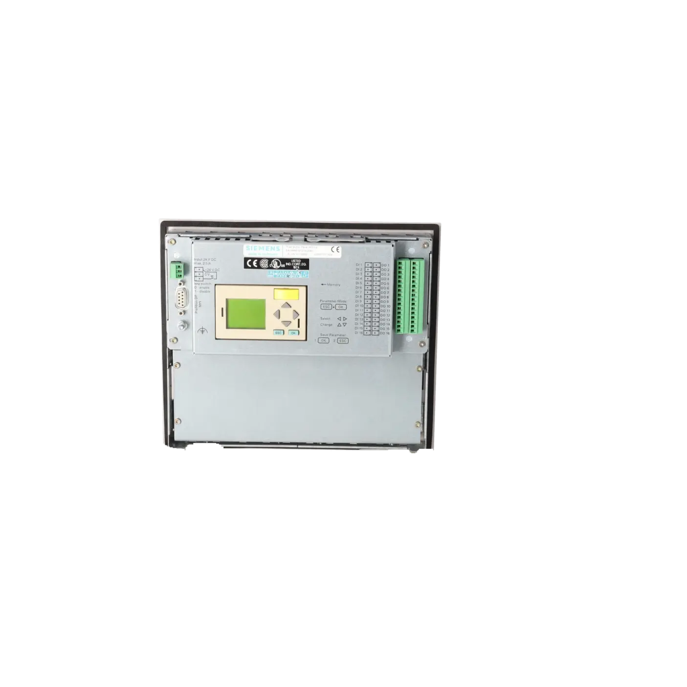
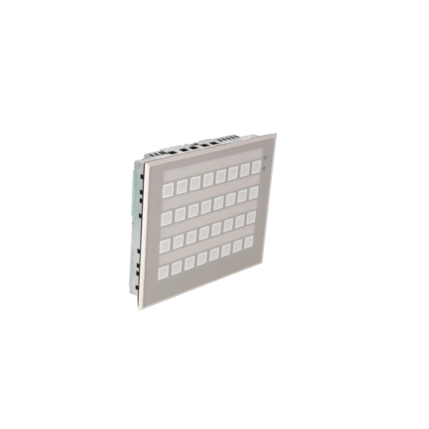
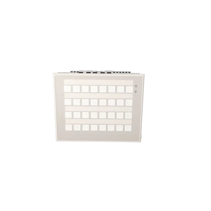
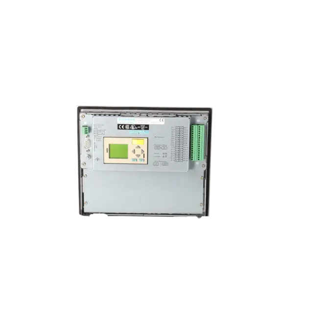
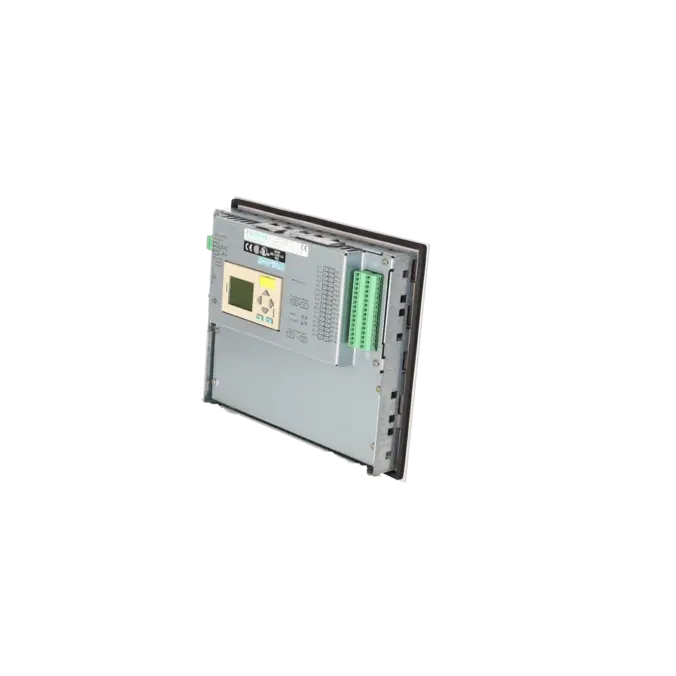
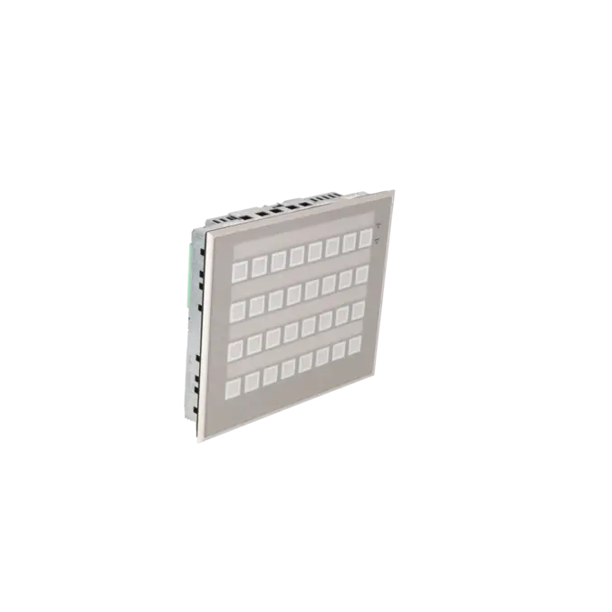
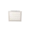
PUSH BUTTON PANEL PP17 II 32 SHORT-STROKE KEYS, 32 SURFACE LEDS, 16 DI AND 16 DO TERMINALS PROFIBUS DP12
Services for SIEMENS 6AV3688-3ED13-0AX0
SIEMENS |
6AV3688-3ED13-0AX0 –
additional product information
| Delivery information | |||
|---|---|---|---|
| Export identifier | AL: N ECCN: EAR99H | ||
| Net weight | 1.4 | ||
| Quantity | 1 Stück | ||
| Packaging quantity | 1 | ||
| Additional product information | |||
|---|---|---|---|
| Product status | EOP: 2017-07-01 | ||
| EAN | 4025515133971 | ||
| UPC | 662643028270 | ||
| Static lot number | 85371098 | ||
| List indicator | ST9.80 | ||
| Product group | 4244 | ||
| Country of origin | DE | ||
| Compliance with the substance restrictions according to RoHS directive | Since: 20991231 | ||
| Product classifications | Version | Classification | |
|---|---|---|---|
| eClass | 4 | 27-33-02-01 | |
| eClass | 5.1 | 27-24-23-05 | |
| eClass | 6.0 | 27-24-23-05 | |
| ETIM | 3 | / | |
| ETIM | 4 | EC001415 | |
| ETIM | 5 | EC001415 | |
What is 6AV3688-3ED13-0AX0 and where is it used?
The SIEMENS 6AV3688-3ED13-0AX0 is a SIMATIC HMI Push Button Panel PP17-II designed for industrial operator control tasks without graphical visualisation. The device combines 32 short-stroke pushbuttons, 32 directly assigned LEDs, as well as 16 digital inputs and 16 digital outputs in a compact front panel. This makes the PP17-II particularly suitable for machines and systems where robust, clearly defined operating and signalling functions are required. Thanks to its support for MPI and PROFIBUS-DP communication, it is primarily used in existing installations, retrofit projects and traditional SIMATIC environments where the existing operating concept is to be retained with minimal modification.
Overview of the key technical data and what it means
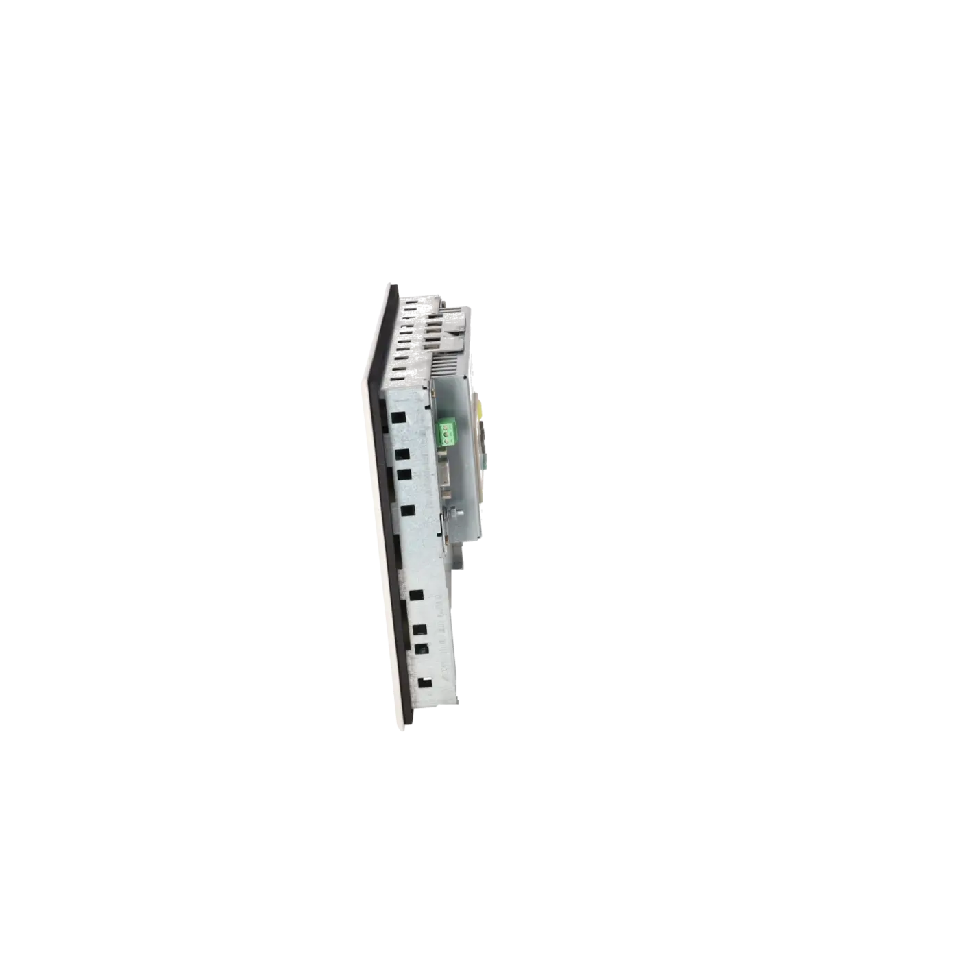
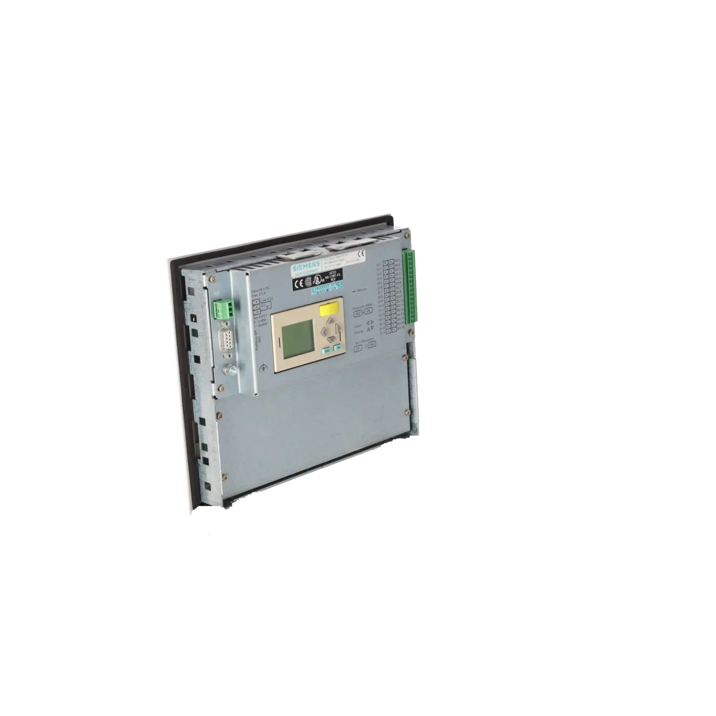
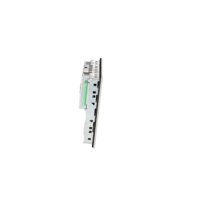
Technically, the PP17-II is designed for control cabinet and front-panel installation in industrial environments. Key specifications include an 18 to 30 V DC supply voltage, IP65 protection at the front, IP20 protection at the rear, an operating temperature range of 0 to 55 °C, front dimensions of 240 x 204 mm, a panel cut-out of 226 x 190 mm and an installation depth of 53 mm. The 32 LEDs support three colour modes, and integrated lamp and key testing functions are also provided. For maintenance personnel, this means robust machine-level operation, clear status feedback via LEDs rather than display diagnostics and straightforward integration into existing I/O and bus structures. For purchasing and engineering departments, supply voltage, installation dimensions and communication interfaces are particularly important to ensure that a replacement unit can be integrated mechanically and electrically without additional complications.
Product status, life-cycle status and obsolescence
The life-cycle status of this panel is a key consideration for procurement. Based on the evaluated data, product status EOP (End of Production) with an effective date of 01 July 2017 is assigned to 6AV3688-3ED13-0AX0. This indicates that the device is no longer part of the active product portfolio and is generally sourced through service providers, exchange programmes or existing stock. No clearly verified manufacturer-designated successor could be identified in the reviewed Siemens and product documentation. Therefore, any replacement should always be evaluated against the actual machine environment: communication interface, panel cut-out, I/O structure, LED control functions and PLC concept must remain compatible. Especially on older production lines, repair services, exchange units and strategic spare-parts stocking are often the safest ways to reduce downtime risks associated with obsolescence.
Available EICHLER services and when they are relevant
For operators of older machines, not only the part number but also the right support strategy is important. EICHLER offers repair, exchange, used equipment and new units on request for this assembly. Repair services include technical cleaning, preventive maintenance, comprehensive functional testing and a minimum 24-month warranty. This is particularly relevant when the original unit must fit mechanically without modification or when machine redesign is to be avoided. An exchange unit is advantageous when rapid machine restart is the priority. Tested used equipment is a practical option when an obsolete component must be sourced economically. These options help ensure the continued operation of existing systems, even when standard manufacturer availability is no longer the primary source of supply.
| Attribute | Value |
|---|---|
| Product type designation | PP17-II |
| Control elements | |
| With parameterizable keys | Yes |
| Keyboard fonts | |
| ● Membrane keyboard | |
| — user-definable label membrane keys | Yes |
| ● Function keys | |
| — Number of function keys | 32 |
| ● Short-stroke keys | |
| — Number of short-stroke keys | 32 |
| Expansions for operator control of the process | |
| ● DP direct LEDs (LEDs as S7 output I/O) | 32 |
| ● Number of color modes for LED | 3 |
| ● Direct keys (keys as S7 input I/O) | 32 |
| Installation type/mounting | |
| Mounting type | Clamp terminals |
| Mounting position | vertical |
| Rack mounting | No |
| Front mounting | Yes |
| Rail mounting | No |
| Wall mounting/direct mounting | No |
| Mounting in portrait format possible | No |
| Mounting in landscape format possible | Yes |
| maximum permissible angle of inclination without external ventilation | 35° |
| Number of slots for command devices and signaling units | 0 |
| Supply voltage | |
| Type of supply voltage | DC |
| permissible range, lower limit (DC) | 18 V |
| permissible range, upper limit (DC) | 30 V |
| Input current | |
| Starting current inrush I²t | 0.03 A²·s |
| Digital inputs | |
| Number of digital inputs | 16 |
| Input voltage | |
| ● Rated value (DC) | 24 V |
| Digital outputs | |
| Number of digital outputs | 16 |
| ● in groups of | 4 |
| Short-circuit protection | Yes |
| Switching capacity of the outputs | |
| ● with resistive load, max. | 100 mA |
| ● with inductive load, max. | 100 mA; max. 2 watts |
| ● on lamp load, max. | 2 W |
| Output voltage | |
| ● Rated value (DC) | 24 V |
| Total current of the outputs | |
| ● Current per channel, max. | 100 mA |
| ● Current per group, max. | 500 mA |
| Interfaces | |
| Number of industrial Ethernet interfaces | 0 |
| Number of PROFINET interfaces | 0 |
| Industrial Ethernet | |
| ● Industrial Ethernet status LED | 0 |
| ● Number of ports of the integrated switch | 0 |
| Protocols | |
| PROFINET | No |
| Supports protocol for PROFINET IO | No |
| PROFINET CBA | No |
| IRT | No |
| PROFIsafe | No |
| PROFIBUS | Yes |
| EtherNet/IP | No |
| MPI | Yes |
| AS-Interface | No |
| EIB/KNX | No |
| Protocols (Ethernet) | |
| ● TCP/IP | No |
| Redundancy mode | |
| Media redundancy | |
| — MRP | No |
| Further protocols | |
| ● AS-Interface Safety at Work | No |
| ● CAN | No |
| ● Data-Highway | No |
| ● DeviceNet | No |
| ● DeviceNet Safety | No |
| ● Foundation Fieldbus | No |
| ● INTERBUS | No |
| ● INTERBUS-Safety | No |
| ● Local Operating Network | No |
| ● MODBUS | No |
| ● SafetyBUS p | No |
| ● SERCOS | No |
| ● SUCOnet | No |
| ● other bus systems | No |
| Test commissioning functions | |
| Illuminant test | Yes |
| Key and signal lamp test | Yes; automatically when switching on |
| EMC | |
| Emission of radio interference acc. to EN 55 011 | |
| ● Limit class A, for use in industrial areas | Yes |
| ● Limit class B, for use in residential areas | No |
| Degree and class of protection | |
| IP (at the front) | IP65 |
| IP (rear) | IP20 |
| NEMA (front) | |
| ● Enclosure Type 4 at the front | No |
| ● Enclosure Type 4x at the front | No |
| Standards, approvals, certificates | |
| CE mark | Yes |
| cULus | No |
| RCM (formerly C-TICK) | Yes |
| KC approval | No |
| Suitable for safety functions | No |
| Use in hazardous areas | |
| ● ATEX Zone 2 | No |
| ● ATEX Zone 22 | No |
| ● cULus Class I Zone 1 | No |
| ● cULus Class I Zone 2, Division 2 | No |
| ● FM Class I Division 2 | No |
| Marine approval | |
| ● Germanischer Lloyd (GL) | No |
| ● American Bureau of Shipping (ABS) | No |
| ● Bureau Veritas (BV) | No |
| ● Det Norske Veritas (DNV) | No |
| ● Lloyds Register of Shipping (LRS) | No |
| ● Nippon Kaiji Kyokai (Class NK) | No |
| ● Polski Rejestr Statkow (PRS) | No |
| Ambient conditions | |
| Ambient temperature during operation | |
| ● min. | 0 °C |
| ● max. | 55 °C |
| Operation (vertical installation) | |
| — For vertical installation, min. | 0 °C |
| — For vertical installation, max. | 55 °C |
| Operation (max. tilt angle) | |
| — At maximum tilt angle, min. | 0 °C |
| — At maximum tilt angle, max. | 55 °C |
| Ambient temperature during storage/transportation | |
| ● min. | -20 °C |
| ● max. | 60 °C |
| Relative humidity | |
| ● Operation, max. | 95 % |
| configuration / header | |
| Configuration software | |
| ● STEP 7 Basic (TIA Portal) | Yes |
| ● STEP 7 Professional (TIA Portal) | Yes |
| Functionality under WinCC (TIA Portal) | |
| Process coupling | |
| ● S7-1200 | Yes |
| ● S7-1500 | Yes |
| ● S7-200 | No |
| ● S7-300/400 | Yes |
| ● LOGO! | No |
| ● WinAC | Yes |
| ● SINUMERIK | No |
| ● SIMOTION | No |
| ● Allen Bradley (EtherNet/IP) | No |
| ● Allen Bradley (DF1) | No |
| ● Mitsubishi (MC TCP/IP) | No |
| ● Mitsubishi (FX) | No |
| ● OMRON (FINS TCP) | No |
| ● OMRON (LINK/Multilink) | No |
| ● Modicon (Modbus TCP/IP) | No |
| ● Modicon (Modbus) | No |
| Mechanics/material | |
| Enclosure material (front) | |
| ● Plastic | No |
| ● Aluminum | Yes |
| ● Stainless steel | No |
| Service life | |
| ● Short-stroke keys (in switching cycles) | 1 500 000 |
| ● LEDs (ON period) | 100 % |
| Dimensions | |
| Width of the housing front | 240 mm |
| Height of housing front | 204 mm |
| Mounting cutout, width | 226 mm |
| Mounting cutout, height | 190 mm |
| Overall depth | 53 mm |
| Weights | |
| Weight (without packaging) | 1 130 g |
| Fault description | Possible solution |
|---|---|
| Why does my PP17-II display the message NO PLC? | This message indicates that no connection to the PLC can be established. First check the bus cable, connectors, shielding and power supply. Then verify the interface parameters configured in the panel. For MPI, the most important parameters are baud rate, PLC address, rack number and slot number. For PROFIBUS-DP, the slave address, bus configuration and GSD configuration used in the project must match the actual installation. Siemens explicitly states that NO PLC can result from faulty wiring or an incorrect interface configuration. |
| Why does the PP17-II report EEPROM ERR? | EEPROM ERR indicates a faulty or missing memory module. Ensure that the memory module is installed correctly and that the electrical contacts are clean and secure. If the message remains, the module should be replaced. The memory module is important because it stores the device and communication parameters. If it fails, the panel can no longer operate with valid configuration data. |
| Why does the PP17-II report EEPROM INV? | This message indicates that the memory module contains invalid data. Reconfigure the communication interface in the Push Button Panel and verify that all configured communication parameters match the actual installation. If the fault persists, the memory module is the most likely cause and should be checked or replaced. |
| Why is the ERROR LED permanently illuminated on the PP17-II? | Siemens distinguishes between several conditions: a flashing ERROR LED indicates a lamp or key test, a continuously illuminated ERROR LED during hardware test mode indicates that the hardware test is active, and a continuously illuminated ERROR LED during normal operation indicates a communication or software fault. Therefore, always note the message shown in the display and relate it to a specific fault such as NO PLC, EEPROM ERR, EEPROM INV or PP START. If the hardware test itself reports an error, repair of the device is recommended. |
| Why is DO01 flashing on the PP17-II although the PLC bit is 0? | The PP17-II includes integrated flashing and colour modes for LEDs. According to Siemens, these functions are controlled by two control bits in consecutive bytes. In a discussion concerning the same device, it was therefore recommended to check not only the actual output bit but also overlapping accesses, cross-references and LED mode parameterisation. If a second control bit is unintentionally set, a flashing function may be activated even though the observed primary bit remains at 0. |
| Why does the PP17-II display the message NO PAR. DB? | This message means that the configured parameter data block does not exist in the PLC. Create the required configuration data block in the PLC or verify that the correct DB number is configured in the panel. This fault commonly occurs during commissioning, after a CPU replacement or following project modifications when the panel and PLC configurations no longer match. |
Is 6AV3688-3ED13-0AX0 still available or only available through service?
The researched status clearly indicates an obsolete or discontinued product, as the product page lists EOP (End of Production) as of 01 July 2017. At the same time, EICHLER continues to offer repair, exchange, used equipment and new units on request. In practice, this means that supply is often no longer based on standard manufacturer deliveries but rather on service and stock-based solutions, which are significantly more relevant for operators of existing installations.
Which controllers can the PP17-II be used with?
According to Siemens, the PP17-II can be operated via MPI with SIMATIC S7-200, S7-300 and S7-400 controllers. Via PROFIBUS-DP, it is intended for use with SIMATIC S5 and SIMATIC S7 systems. Siemens also describes operation as a standard DP slave on a DP master from other manufacturers, although configuration-related limitations may apply. For procurement purposes, it is therefore important to consider not only the part number but also the existing bus architecture of the machine.
What panel cut-out and power supply does the PP17-II require?
For mechanical installation, the device requires a panel cut-out of 226 x 190 mm. Electrically, the panel operates on a nominal 24 V DC supply within a permissible range of 18 to 30 V DC. These two factors are often the first considerations during retrofit projects, replacements and spare-parts approvals: whether the device fits into the existing enclosure without sheet-metal modifications and whether the available power supply matches the requirements without additional effort.
Can I continue operating an existing PP17-II without rebuilding the entire operator interface?
In many cases, yes, provided that the same part number or a genuinely compatible replacement is used and the existing machine logic remains unchanged. This is one of the reasons why repair and exchange services for Push Button Panels remain economically attractive in existing installations. Siemens also states that the communication parameters are stored in the memory module and can be transferred when replacing the electronics or the complete device. This significantly reduces the effort involved as long as the mechanical installation, bus connection and control concept remain unchanged.
Is there an official successor for 6AV3688-3ED13-0AX0?
No clearly verified manufacturer-designated successor for this exact order number was identified in the reviewed Siemens and product documentation. Therefore, any proposed replacement should not be evaluated solely based on product family or appearance. The decisive factors are communication interface, installation dimensions, I/O assignment, LED function logic and whether the existing machine operating concept can be retained without modification.
Can I create the labelling strips for the PP17-II myself?
Yes. Siemens states that the labelling strips can be produced using standard transparent film or plain paper up to 0.25 mm thick. The strips are inserted from the rear into the designated slots. This is particularly useful when button functions need to be relabelled quickly during a retrofit, machine modification or replacement device installation without making mechanical changes to the front panel.